Download presentation
Presentation is loading. Please wait.

1
ENVI 485 02/20/07 STEAMS AND FLOODING (cont.) MASS WASTING
 MASS WASTING")
2
San Diego River 1852 - Since San Diego Bay was a deeper harbor, and the San Diego River carried heavy silt deposits, it was decided to deflect the San Diego River into False Bay (Mission Bay) The project was completed in two years by Indian laborers who reportedly hauled building materials in baskets. The Darby dike washed out one year after its completion and the San Diego River returned to its old course.

3
San Diego River 1862 – Possibly the largest flood in the history of the San Diego River occurred (almost 100,000 cfs). 1875- New dike constructed (cobblestone face two to three feet thick). A small channel was constructed on the north side of the dike that the river was diverted into the eastern part of Mission Bay.
. A small channel was constructed on the north side of the dike that the river was diverted into the eastern part of Mission Bay..")
4
1927 Flood Photo taken on February 2, 1927 shows the Old Town railroad bridge washed out by the flood. This rail right- of-way still exists - you can see it looking east from I-5; Friars Rd. runs underneath it.

12
Rainiest years in San Diego history 1. 1883-84 25.97 2. 1940-41 24.74 3. 1977-78 18.71 4. 1921-22 18.65 5. 2004-05 22.81

18
River Erosion Erosion types Abrasion by sediments transported by river Hydraulic action of moving water Chemical corrosion Erosion location Down cutting Lateral: Concentrating on the outer bends Headward erosion

19
Meandering River, showing forms and processes

20
Meander on the Colorado River

21
Erosion

22
Koyakuk River, Alaska, showing meander bends, point bar, and cut bank

23
Show animation

25
Braided channels in Granada, southern Spain with multiple channels, steep gradient, and coarse gravel

27
Effects of Land-Use Changes Changes in infiltration rate: Change of the amount of water flowing into a river Soil erosion: Change in the amount of sediments in a river Amount of water and sediments in river: Changes in the velocity of water flow Changes in river’s velocity: Leading the change in river dynamics

28
Effects of Land-Use Changes Forest to farmland Increases soil erosion, stream deposition Increases gradient and velocity Increases river-channel erosion Urban build-up Increases impervious cover Increases certain flood frequency Reduces the lag time of flood

29
Floods In The US

30
Flooding Flooding: Overbank flow condition, discharge greater than channel’s holding capacity Stage: The height of the water level in a river at a given location at a given time Hydrograph: a graph that plots stream discharge (Q) against time (t) Lag time: The amount of time between the occurrence of peak rainfall and the onset of flooding
 against time (t) Lag time: The amount of time between the occurrence of peak rainfall and the onset of flooding")
31
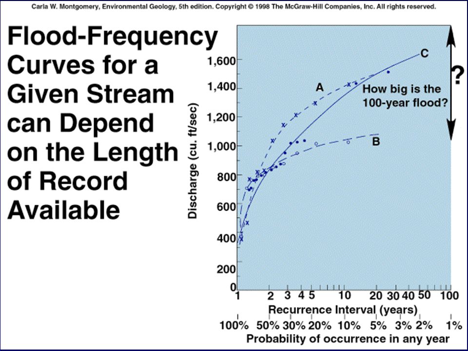
Flood magnitude Recurrence interval –Discharge (Q) on a stream is measured over a period of time (N) –Each flood is ranked (highest discharge = 1) (M) –Recurrence interval: (N + 1)/M Probability of a flood of a given magnitude in a year is 1/recurrence interval
 on a stream is measured over a period of time (N) –Each flood is ranked (highest discharge = 1) (M) –Recurrence interval: (N + 1)/M Probability of a flood of a given magnitude in a year is 1/recurrence interval")
34
Example of a discharge-frequency curve for Patrick River

36
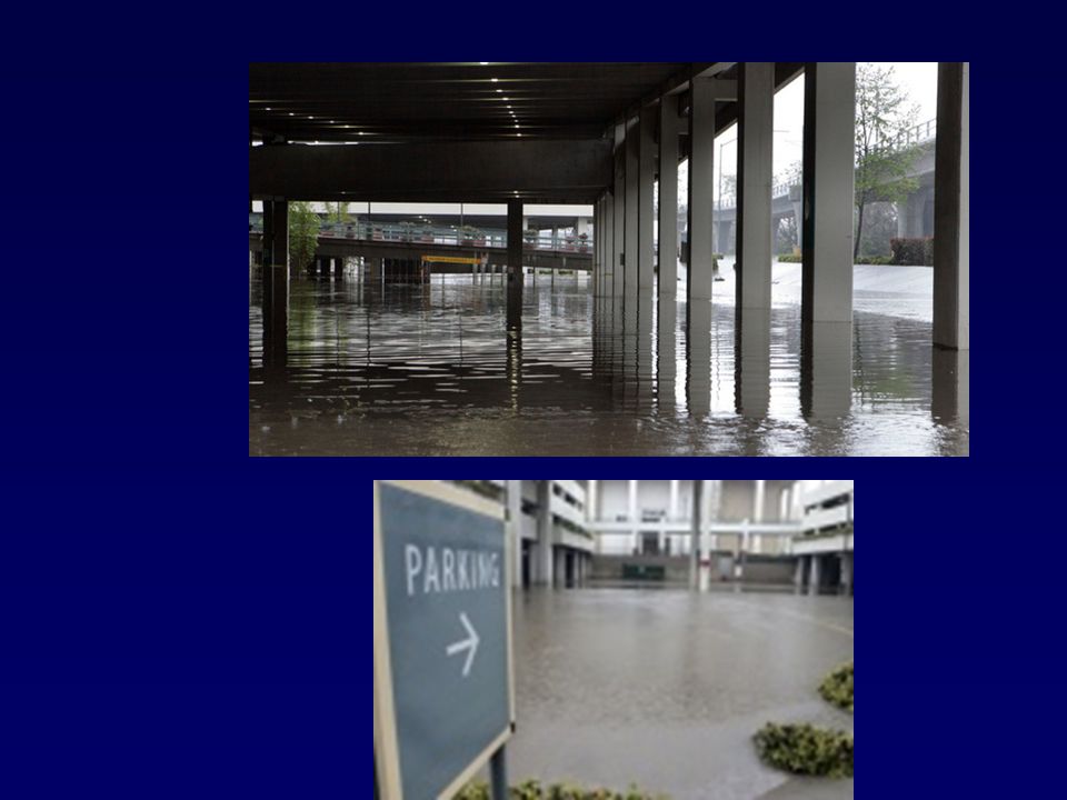
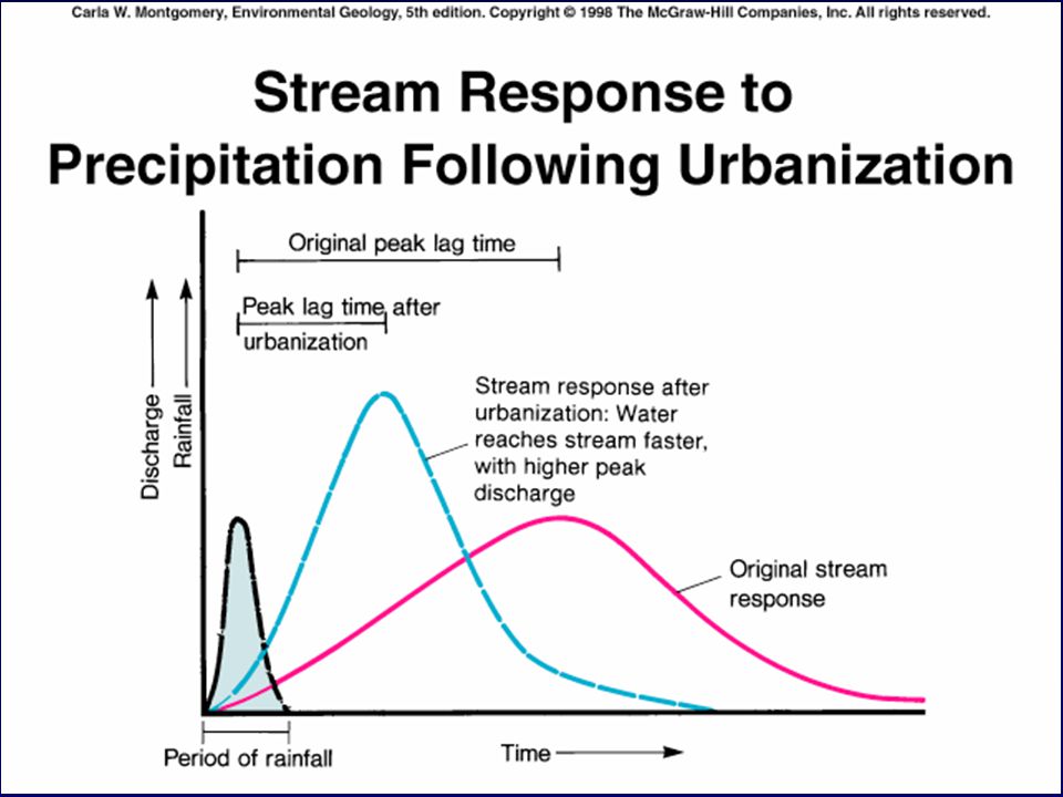
Urban development and flooding Flooding usually increased by urban development –Affected by impervious cover –Storm sewers More water reaches stream Water reaches stream faster Affects the relationship between rainfall-runoff –Reduced lag time = “flashy discharge”

39
Smaller floods are more affected by urbanization than larger floods

40
Mean annual flood: RI = 2.23

43
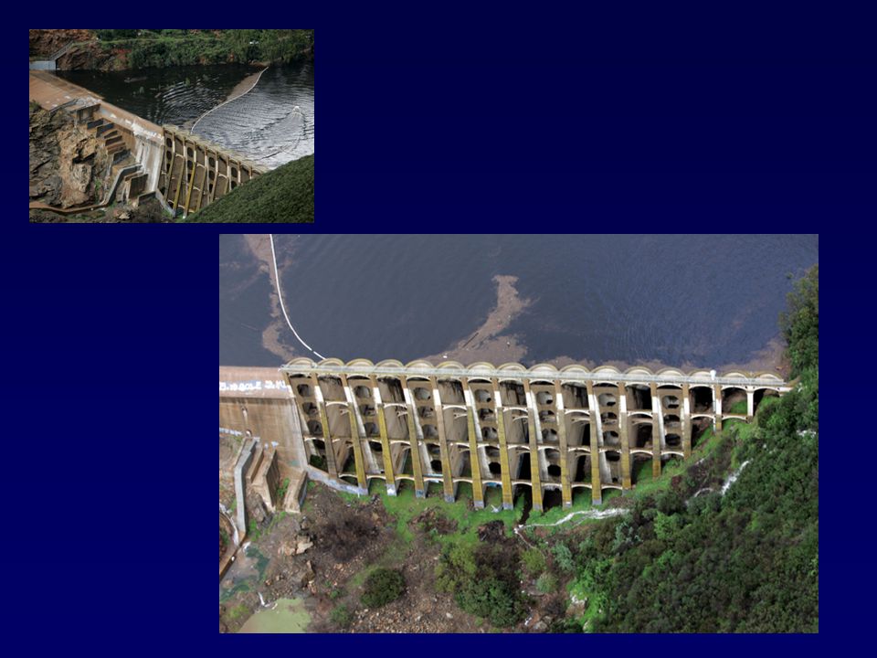
Effect of dam on erosion

44
Regulation of the Floodplain Floodplain belongs to the river system and the river WILL reoccupy it. Flood hazard mapping –Floodway & floodway fringe district Area of the floodplain covered by a 100 year flood O.k. for some uses

45
Adjustments to Flood Hazards The structural approach Engineering barriers: Levee augmentation Channelization River-channel restoration Flood insurance Flood-proofing

46
Floodplain without and with levees

47
07_28b Placing riprap to defend the bank

48
Natural vs. channelized stream

49
Concrete channel in LA

50
07_28a Urban stream restoration by controlling erosion and deposition

51
Landslide/Mass wasting

52
Factors that influence slope stability (all related to shear stress) 1) Slope 2) Fluid 3) Vegetation 4) Earthquakes 5) material type (clays) & geologic structure 6) human activities
 1) Slope 2) Fluid 3) Vegetation 4) Earthquakes 5) material type (clays) & geologic structure 6) human activities")
53
General classification of landslides 1) Slides rock and/or sediment slides along Earth's surface 2) Falls/Topples rocks or soils fall or bounce through the air 3) Flows sediment flows across Earth's surface Slow flow is “creep” Fast flow is an avalanche 4) Complex (combination of the above)
 Slides rock and/or sediment slides along Earth s surface 2) Falls/Topples rocks or soils fall or bounce through the air 3) Flows sediment flows across Earth s surface Slow flow is creep Fast flow is an avalanche 4) Complex (combination of the above)")
54
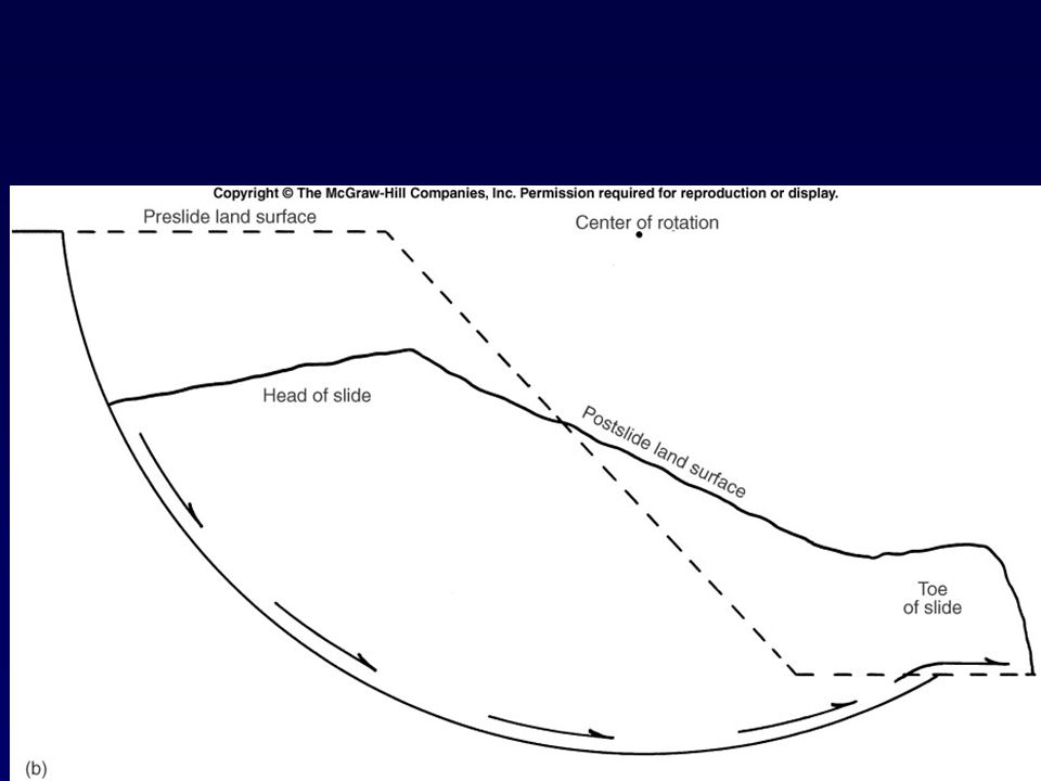
Slides Distinct basal surface Rotational slide (Slump) –Curved basal surface Translational slide –Flat basal surface
 –Curved basal surface Translational slide –Flat basal surface")
57
Mass movements occur when the downward pull of gravity overcomes the forces (usually frictional) resisting it.
 resisting it.")
59
Problematic Formations in California Capay Formation Capistrano Formation Catalina Schist Chico-Martinez Formation Clarmont Shale Contra Costa Group Coyote Formation Fernando Formation Franciscan Formation La Habra Formatino Ladd Formation (Holz shale member) Meganos Formation Mehrten Formation Merced Formation Modelo Formation **Monterey Formation Moreno formation Orinda Formation **Otay Formation Pelona Schist Pico Formation Placerita Series Puente Formation Purisima Formation San Pedro Formation Santa Monica Slate Sespe Formation Siesta Formation Topanga Formation Trabuco Formation Valley Springs Formation Vaqueros Formation
 Meganos Formation Mehrten Formation Merced Formation Modelo Formation **Monterey Formation Moreno formation Orinda Formation **Otay Formation Pelona Schist Pico Formation Placerita Series Puente Formation Purisima Formation San Pedro Formation Santa Monica Slate Sespe Formation Siesta Formation Topanga Formation Trabuco Formation Valley Springs Formation Vaqueros Formation")
60
Slope Stability Analysis Requires an accurate characterization of: –1. Surface topography, –2. Subsurface stratigraphy, –3. Subsurface water levels and possible subsurface flow patterns, –4. Shear strength of materials through which the failure surface may pass, and –5. Unit weight of the materials overlying potential failure planes.

61
Don’t Forget Earthquakes! A seismic slope stability analysis requires consideration of each of the above factors for static stability, as well as characterization of: –1. Design-basis earthquake ground motions at the site, and –2. Earthquake shaking effects on the strength and stress-deformation behavior of the soil, including pore pressure generation and rate effects (which can decrease or increase the shear strengths relative to the static case).
..")
62
Recognition and avoidance of landslide hazards Detailed analysis of hillslope stability requires the expertise of engineers. Planners need to decide; –(1) whether a site is in a stable area –(2) whether there is enough uncertainty to warrant a detailed site investigation by an expert –(3) whether the site is so obviously unstable that it should be avoided.
 whether a site is in a stable area –(2) whether there is enough uncertainty to warrant a detailed site investigation by an expert –(3) whether the site is so obviously unstable that it should be avoided..")
63
California Landslide Laws and Regulations The State of California requires analysis of the stability of slopes for certain projects. The authority to require analysis of slope stability is provided by the Seismic Hazards Mapping Act of 1990 (Chapter 7.8, Sections 2690 et. seq., California Public Resources Code). The Act protects public safety from the effects of strong ground shaking, liquefaction, landslides, or other ground failure caused by earthquakes. The Act is a companion and complement to the Alquist-Priolo Earthquake Fault Zoning Act. Chapters 18 and 33 (formerly 70) of the Uniform/California Building Code provide the authority for local Building Departments to require geotechnical reports for various projects.
. The Act protects public safety from the effects of strong ground shaking, liquefaction, landslides, or other ground failure caused by earthquakes. The Act is a companion and complement to the Alquist-Priolo Earthquake Fault Zoning Act. Chapters 18 and 33 (formerly 70) of the Uniform/California Building Code provide the authority for local Building Departments to require geotechnical reports for various projects..")
64
Techniques for evaluating landslide hazards (1) Past hillslope failures –Direct evidence in airphoto, indirect evidence of altered vegetation, subtle topographic features, deposits formed by hillslope failures. (2) Conditions that are conductive to hillslope failures –Steep slope gradients, mechanically weak geological material, poor permeability, high water table, seepage in the vicinity of steep slope. (3) De-stabilizing effects of planned development Undercutting, overloading, changing hydrologic conditions.
 Conditions that are conductive to hillslope failures –Steep slope gradients, mechanically weak geological material, poor permeability, high water table, seepage in the vicinity of steep slope. (3) De-stabilizing effects of planned development Undercutting, overloading, changing hydrologic conditions..")
65
Planning Avoid building on steep slopes Avoid building in hazardous areas Restrict or eliminate human activities in these zones Make wise use of hazards maps

66
Site Investigation and Geologic Studies of Slope Stability 1. Study and review of published and unpublished geologic information (both regional and site specific), and of available stereoscopic and oblique aerial photographs. 2. Field mapping and subsurface exploration. 3. Analysis of the geologic failure mechanisms that could occur at the site during the life span of the project. 4. Presentation and analysis of the data, including an evaluation of the potential impact of geologic conditions on the project.
, and of available stereoscopic and oblique aerial photographs. 2. Field mapping and subsurface exploration. 3. Analysis of the geologic failure mechanisms that could occur at the site during the life span of the project. 4. Presentation and analysis of the data, including an evaluation of the potential impact of geologic conditions on the project..")
67
Landslide Mitigation Slopes that possess factors of safety less than required by the governing agency, or with unacceptably large seismic slope displacements, require avoidance or mitigation to improve their stability.

68
Landslide Mitigation (1) hazard avoidance, (2) grading to improve slope stability, (3) reinforcement of the slope or improvement of the soil within the slope, and (4) reinforcement of the structure built on the slope to tolerate the anticipated displacement.
 hazard avoidance, (2) grading to improve slope stability, (3) reinforcement of the slope or improvement of the soil within the slope, and (4) reinforcement of the structure built on the slope to tolerate the anticipated displacement.")
69
Avoidance The simplest method of mitigation may be to avoid construction on or adjacent to a potentially unstable slope. –The setback distance is based on the slope configuration, probable mode of slope failure, factor of safety, and potential consequences of failure. –The required setback cannot generally be accurately calculated, therefore a large degree of engineering/geologic judgment is required.

70
Grading Grading can often be performed to entirely or partially remove potentially unstable soil The available grading methods range from: –Reconfiguration of the slope surface to a stable gradient (flattening) –Removal and recompaction of a soil that is preferentially weak in an unfavorable direction and its replacement with a more homogeneous soil with a higher strength.
 –Removal and recompaction of a soil that is preferentially weak in an unfavorable direction and its replacement with a more homogeneous soil with a higher strength.")
71
Engineered Stabilization A grading solution to a slope stability problem is not always feasible due to physical constraints such as property-line location, location of existing structures, the presence of steep slopes, and/or the presence of very low-strength soil. In such cases, it may be feasible to mechanically stabilize the slide mass or to improve the soil with admixture stabilization.

72
Mechanical Stabilization Retaining walls Deep foundations (i.e., piles or drilled shafts) Soil reinforcement with geosynthetics, tieback anchors, and soil nails. Common admixture stabilization measures include cement and lime treatment as well as Geofibers.

73
concrete

74
Dewatering Water can reduce shear strength of the soil, reduce the shear resistance through buoyancy effects, and impose seepage forces causing slope failure. Both passive and active dewatering/subsurface-water- control systems can be used. –A slope can be "passively" dewatered by installing slightly inclined gravity dewatering wells into the slope. –Vertical pumped-wells also can be utilized to lower subsurface water levels. The effectiveness of dewatering wells is dependent on the permeability of the soil.

75
3) fluid removal
 fluid removal")
77
Containment Loose materials, such as colluvium, slopewash, slide debris, and broken rock, can be collected by a containment structure capable of holding the volume of material that is expected to fail. The containment structure type, size, and configuration will depend on the anticipated volume to be retained. –Debris basins, graded berms, graded ditches, debris walls, and slough walls can be used. In some cases, debris fences may be permitted, although those structures often fail upon high-velocity impact.

78
Deflection Walls or berms that are constructed at an angle to the expected path of a debris flow can be used to deflect and transport debris around a structure. Required channel gradients may range from 10 to 40 percent depending on the expected viscosity of the debris and whether the channel is earthen or paved.

79
2 ) retention structures
 retention structures")
80
Diversion walls, Taiwan

81
Close-up of previous slide; note tires for cushioning

82
Flumes for diverting debris flows, Lamosano, Italy

83
Slope Protection for Rock Slopes Woven wire mesh is hung from anchors drilled into stable rock and is placed over the slope face to help keep dislodged rocks from bouncing as they fall. Wire mesh systems can contain large rocks (3 feet in diameter) traveling at fast speeds. It is also possible to hold rocks in position with cables, rock bolts, or gunite slope covering.
 traveling at fast speeds. It is also possible to hold rocks in position with cables, rock bolts, or gunite slope covering..")
84
Chicken wire

86
Resistant Structures Examples of structural systems that can resist damage include mat foundations and very stiff, widely spaced piles. Mat foundations are designed to resist or minimize deflection or distortion of the structure resting on the mat as a result of permanent displacement of the underlying ground. The mat foundation itself may move or settle differentially, but the mat is sufficiently stiff to reduce bending in the structure to a tolerable level.

87
Resistant Structures Another instance where a building can be designed to resist damage to earth movement involves structures built over landslides experiencing plastic flow. Flows that do not move as a rigid block can be penetrated with a series of widely spaced stiff piles. –These piles are designed to resist loading imposed by moving material.

88
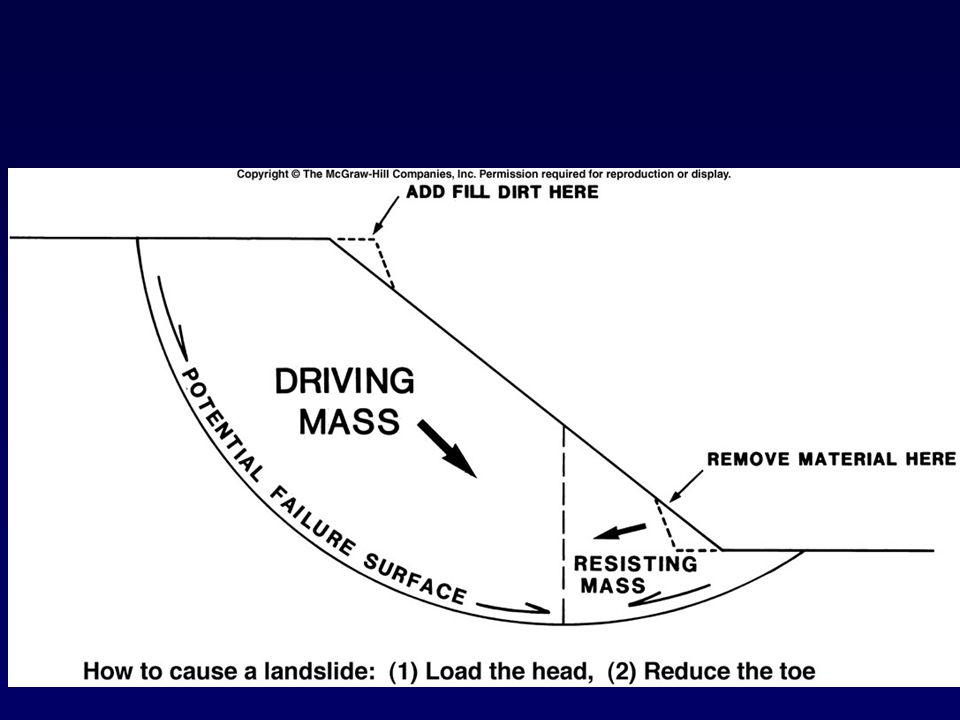
Summary - Reduction of landslide hazards 1 ) slope reduction Reduce the slope angle Supporting material at base of slope Reduce the load by removing rock or soil 2) retaining structures 3) fluid removal 4) vegetation 5) Others (soil hardening, piles, rock bolts)
 slope reduction Reduce the slope angle Supporting material at base of slope Reduce the load by removing rock or soil 2) retaining structures 3) fluid removal 4) vegetation 5) Others (soil hardening, piles, rock bolts)")
Similar presentations


 MASS WASTING.>")

 Chapter 8 Mass movements occur when the shearing stress acting on rocks or soil exceeds the shear strength of the material.>")


