Download presentation
Presentation is loading. Please wait.

1
POWER ELECTRONICS Instructor: Eng.Moayed N. EL Mobaied The Islamic University of Gaza Faculty of Engineering Electrical Engineering Department بسم الله الرحمن الرحيم EELE 5450 — Fall 2009-2010 Lecture 27

2
Three switches conducting The conducting sequence is as follows (each device conducts for a 180 o period):
:")
4
Three conducting devices- line voltage and current Values of line voltage and line (also phase) current for 60 o intervals are shown, from which the waveforms are constructed. The other two lines have identical values, displaced mutually by 120 o

5
Three conducting devices- line voltage and current Values of line voltage and line (also phase) current for 60 o intervals are shown, from which the waveforms are constructed. The other two lines have identical values, displaced mutually by 120 o

6
Comparing rms line currents

7
Two switches conducting

8
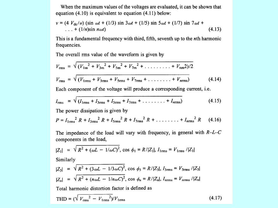
INVERTER HARMONICS

12
SINUSOIDAL PULSE-WIDTH MODULATION One of the methods used to reduce the low frequency harmonics in the inverter waveform is sinusoidal pulse-width modulation. In this method, a reference copy of the desired sinusoidal waveform, the modulating wave, is compared to a much higher frequency triangular waveform, called the carrier wave The resulting drive signals cause multiple turn-on of the inverter switches in each half-cycle with variable pulse width to produce a quasi-sine wave of load voltage. The pulse width increases from a very narrow width at the start of each cycle to a maximum width in the middle of each cycle. Then the pulse width reduces again after maximum until its minimum width at the end of the half-cycle period.

13
SINUSOIDAL PULSE-WIDTH MODULATION Typically in the comparator when the sine wave voltage exceeds the triangular wave voltage, the load voltage is +Vdc, and when the triangular wave voltage exceeds the sine wave voltage, the load voltage is -Vdc.

14
SINUSOIDAL PULSE-WIDTH MODULATION End of Lecture Problem set : (SELF-ASSESSMENT TEST, PROBLEMS) due to 6/1/2010
 due to 6/1/2010")
Similar presentations


>")
.>")


 Techniques>")
>")


