Download presentation
Presentation is loading. Please wait.

1
Biology 177: Principles of Modern Microscopy Lecture 03: Microscope optics and introduction of the wave nature of light

2
Lecture 3: Microscope Optics Particle and wave nature of light Review of thin lens law Dispersion Aberrations Aperture: Resolution and Brightness Two Most Important Microscope Components Kohler Illumination N.A. and Resolution

3
Basic properties of light 1.Particle Movement 2.Wave Either property may be used to explain the various phenomena of light

4
Particle versus wave theories of light in the 17 th Century. Corpuscular theory Light made up of small discrete particles (corpuscles) Particles travel in straight line Sir Isaac Newton was biggest proponent Wave theory Different colors caused by different wavelengths Light spreads in all directions First deduced by Robert Hooke and mathematically formulated by Christiaan Hyugens Treatise on Light
 Particles travel in straight line Sir Isaac Newton was biggest proponent Wave theory Different colors caused by different wavelengths Light spreads in all directions First deduced by Robert Hooke and mathematically formulated by Christiaan Hyugens Treatise on Light.")
5
Characteristics of a wave Wavelength (λ) is distance between crests or troughs Amplitude is half the difference in height between crest and trough.
 is distance between crests or troughs Amplitude is half the difference in height between crest and trough.")
6
Characteristics of a wave Period is time it takes two crests or two troughs to travel through the same point in space. Example: Measure the time from the peak of a water wave as it passes by a specific marker to the next peak passing by the same spot. Frequency (ν) is reciprocal of its period = 1/period [Hz or 1/sec] Example: If the period of a wave is three seconds, then the frequency of the wave is 1/3 per second, or 0.33 Hz.
 is reciprocal of its period = 1/period [Hz or 1/sec] Example: If the period of a wave is three seconds, then the frequency of the wave is 1/3 per second, or 0.33 Hz..")
7
Characteristics of a wave Velocity (or speed) at which a wave travels can be calculated from the wavelength and frequency. Velocity in Vacuum (c) = 2.99792458 10 8 m/sec Frequency remains constant while light travels through different media. Wavelength and speed change. c = ν λ
 = m/sec Frequency remains constant while light travels through different media. Wavelength and speed change. c = ν λ.")
8
Characteristics of a wave Phase shift is any change that occurs in the phase of one quantity, or in the phase difference between two or more quantities Small phase differences between 2 waves cannot be detected by the human eye

9
What is white light? A combination of all wavelengths originating from the source

10
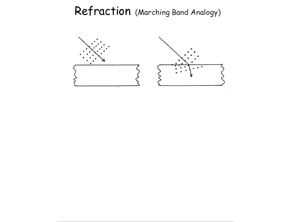
11 11 22 22 Feynman Lectures on Physics, Volume I, Chapter 26 http://feynmanlectures.caltech.edu/I_26.html Refraction as explained through Fermat’s principle of least time Light takes path that requires shortest time Wave theory explains how light “smells” alternate paths

11
Refraction (Marching Band Analogy)
")
15
Thin lens laws 1. Ray through center of lens is straight

16
Thin lens law 2 2. Light rays that enter the lens parallel to the optical axis leaves through Focal Point Focal Point

17
Thin lens law 3 3. Light rays that enter the lens from the focal point exit parallel to the optical axis. Focal Point

18
Applying thin lens law to our object, a gold can

19
1. Ray through center of lens is straight

20
2. Light rays that enter the lens parallel to the optical axis leaves through Focal Point

21
3. Light rays that enter the lens from the focal point, exit parallel to the optical axis.

22
Where the three lines intersect is where that point of the object is located

23
Ray tracing convention for optics generally uses arrows to represent the object.

24
Same three rules can be applied for each point along the object.

25
f o i Thin Lens Equation 1/f = 1/o + 1/i Magnification = i/o

26
For object directly on focal point, rays focused to infinity. Where would this be useful?

27
For object within the focal point, a virtual image is created. Only need two rays to locate object.

28
Of course can use all three rules to trace three rays.

29
Same three rules can be applied to a concave lens.

30
But again two rays are enough to locate virtual image.

31
Concave lens makes virtual image that is smaller no matter where object is located.

32
Principle ray approach works for complex lens assemblies. Focal lengths add as reciprocals: 1/f (total) = 1/f 1 + 1/f 2 +... + 1/f n Remember: for concave lens f is negative
 = 1/f 1 + 1/f /f n Remember: for concave lens f is negative.")
33
Another example: Begin with one convex lens.

34
Another example: Add a second convex lens.

35
Another example: Can determine real image formed by two convex lenses.

36
Dispersion: Separation of white light into spectral colors as a result of different amounts of refraction by different wavelengths of light. Dispersive prisms typically triangular Optical instruments requiring single colors Back to Sir Isaac Newton

37
Monochromator: Optical instrument for generating single colors Used in optical measuring instruments How a monochromator works according to the principle of dispersion Entrance Slit Monochromator (Prism Type) Exit Slit
 Exit Slit")
38
Why Isaac Newton did not believe the wave theory of light Experiment with two prisms If light was wave than should bend around objects Color did not change when going through more glass Isaac Newton's diagram of an experiment on light with two prisms. From a letter to the Royal Society, 6th June 1672

39
Dispersion of glass: disperses the different wavelengths of white light Question: what’s wrong with this figure? Material Blue (486nm) Yellow (589nm) Red (656nm) Crown Glass1.524 1.517 1.515 Flint Glass1.6391.6271.622 Water1.3371.3331.331 Cargille Oil1.5301.5201.516
 Yellow (589nm) Red (656nm) Crown Glass Flint Glass Water Cargille Oil")
40
Dispersion of glass: disperses the different wavelengths of white light Question: what’s wrong with this figure? Material Blue (486nm) Yellow (589nm) Red (656nm) Crown Glass1.524 1.517 1.515 Flint Glass1.6391.6271.622 Water1.3371.3331.331 Cargille Oil1.5301.5201.516 θ n 1 sin θ 1 = n 2 sin θ 2
 Yellow (589nm) Red (656nm) Crown Glass Flint Glass Water Cargille Oil θ n 1 sin θ 1 = n 2 sin θ 2.")
41
Homework 1: The index of refraction changes with wavelength (index is larger in blue than red). How would you need to modify this diagram of the rays of red light to make it appropriate for blue light? f o i

42
Higher index of refraction results in shorter f Chromatic Aberration Lateral (magnification) Axial (focus shift) Shift of focus Change in magnification f o i
 Axial (focus shift) Shift of focus Change in magnification f o i")
43
Optical Aberrations: Imperfections in optical systems Chromatic (blue = shorter focal length) Spherical Curvature of field
 Spherical Curvature of field")
44
Spherical Aberration Zone of Confusion

45
Curvature of field : Flat object does not project a flat image (Problem: Cameras and Film are flat) f o i
 f o i")
46
Optical Aberrations: Imperfections in optical systems Chromatic (blue = shorter focal length) Spherical (rays near edge of lens bent more) Curvature of field (worse near edges) Potential Solution: Stop down lens
 Spherical (rays near edge of lens bent more) Curvature of field (worse near edges) Potential Solution: Stop down lens")
47
Spherical Aberration is reduced by smaller aperture Less confused “Zone of Confusion”

48
Optical Aberrations: Imperfections in optical systems Chromatic (blue = shorter focal length) Spherical (rays near edge of lens bent more) Curvature of field (worse near edges) Potential Solution: Stop down lens Problem: Brightness and Resolution
 Spherical (rays near edge of lens bent more) Curvature of field (worse near edges) Potential Solution: Stop down lens Problem: Brightness and Resolution")
49
Need to Understand Numerical Aperture (N.A.) Dimensionless number defining range of angles over which lens accepts light. Refractive index (η) times half-angle ( ) of maximum cone of light that can enter or exit lens N.A. = sin
 times half-angle ( ) of maximum cone of light that can enter or exit lens N.A. = sin .")
50
Larger Aperture collects more light

51
N.A. = sin = index of refraction Material Refractive Index Air1.0003 Water 1.33 Glycerin 1.47 Immersion Oil 1.515 Note: sin ≤1, therefore N.A. ≤

52
N.A. and immersion important for resolution and not loosing light to internal reflection.

53
How immersion medium affects the true N.A. and, consequently, resolution With immersion oil (3) n=1.518 No Total Reflection Objective aperture fully usable N.A. max = 1.45 > Actual angle : 3 2 1 No immersion (dry) Max. Value for = 90° (sin = 1) Attainable: sin = 0.95 ( = 72°) Actual angle : 1)Objective 2)Cover Slip, on slide 3)Immersion Oil No oil Oil Beampath Snell’s Law: n 1 sin 1 = n 2 sin 2
 n=1.518 No Total Reflection Objective aperture fully usable N.A. max = 1.45 > Actual angle : 3 2 1 No immersion (dry) Max. Value for = 90° (sin = 1) Attainable: sin = 0.95 ( = 72°) Actual angle : 1)Objective 2)Cover Slip, on slide 3)Immersion Oil No oil Oil Beampath Snell’s Law: n 1 sin 1 = n 2 sin 2.")
54
sin critical = 1 / 2 Internal reflection depends on refractive index differences

55
N.A. has a major effect on image brightness Transmitted light Brightness = fn (NA 2 / magnification 2 ) Epifluorescence Brightness = fn (NA 4 / magnification 2 ) 10x 0.5 NA is 3 times brighter than 10x 0.3NA 10x 0.5 NA is 8 times brighter than 10x 0.3NA
 Epifluorescence Brightness = fn (NA 4 / magnification 2 ) 10x 0.5 NA is 3 times brighter than 10x 0.3NA 10x 0.5 NA is 8 times brighter than 10x 0.3NA.")
56
N.A. has a major effect on image resolution Minimum resolvable distance d min = 1.22 / (NA objective +NA condenser )
.")
57
Optical Aberrations: Imperfections in optical systems Chromatic (blue = shorter focal length) Spherical (rays near edge of lens bent more) Curvature of field (worse near edges) BAD Potential Solution: Stop down lens Problem: Brightness and Resolution Real Solution: Good Optical Engineering
 Spherical (rays near edge of lens bent more) Curvature of field (worse near edges) BAD Potential Solution: Stop down lens Problem: Brightness and Resolution Real Solution: Good Optical Engineering")
58
The most important microscope component The Objective Here is where good optical engineering really pays off

59
Example: Achromat doublet Second lens creates equal and opposite chromatic aberration BUT - at only one or two wavelength(s)
")
60
“White” Light Dispersion in a plane-parallel glass plate (e.g. slide, cover slip, window of a vessel) Chromatic Aberration can be defined as “unwanted” dispersion.
 Chromatic Aberration can be defined as unwanted dispersion..")
61
404.7 h Violet Hg 435.8 g Blue Hg 480.0 F‘ Blue Cd 486.1 F Blue H 546.1 e Green Hg 587.6 d Yellow He 589 D Sodium 643.8 C‘ Red Cd 656.3 C Red H 706.5 nm r Red He Energy Named Spectral Lines Where did these named lines come from?

62
Fraunhofer lines Dark lines in solar spectrum First noted by William Wollaston in 1802 Independently discovered by Joseph Fraunhofer in 1814 Absorption by chemical elements (e.g. He, H, Na) "Hiding in the Light" Joseph Fraunhofer 1787-1826
 Hiding in the Light Joseph Fraunhofer")
63
Why do we care about Fraunhofer lines?

64
Fraunhofer was a maker of fine optical glass Special glass he made allowed him to see what Newton did not Ernst Abbe, working with Otto Schott, would use these named spectral lines to characterize glass for microscope optics Ernst Abbe (1840-1905) Otto Schott (1851-1935)
 Otto Schott ( )")
65
Abbe number (V) Measure of a material’s dispersion in relation to refractive index Refractive indices at wavelengths of Fraunhofer D-, F- and C- spectral lines (589.3 nm, 486.1 nm and 656.3 nm respectively) Instead of Na line can use He (V d ) or Hg (V e ) lines High values of V indicating low dispersion (low chromatic aberration)
 Measure of a material’s dispersion in relation to refractive index Refractive indices at wavelengths of Fraunhofer D-, F- and C- spectral lines (589.3 nm, nm and nm respectively) Instead of Na line can use He (V d ) or Hg (V e ) lines High values of V indicating low dispersion (low chromatic aberration)")
66
Abbe number (V)
")
67
Objective names and corrections Corrections:ChromaticSphericalOther Achromat2λ2λ- Apochromat3λ3λ2λ2λ PlanApochromat4-7λ3λ3λFlat field Fluor or Fluarfewλ Max light Neo Fluar2-3λ

68
Corrected Wavelength (nm): UVVISIR Plan Neofluar - -(435) 480546 -644 - - Plan Apochromat - - 435 480 546 -644 - - C-Apochromat365405 435 480 546608644 - - IR C-Apochromat - - 435 480 546608644800 1064 Definitions: Color Correction (axial)
: UVVISIR Plan Neofluar - -(435) Plan Apochromat C-Apochromat IR C-Apochromat Definitions: Color Correction (axial)")
69
Example: Achromat doublet Convex lens of crown glass: low η and high Abbe number Concave lens of flint glass: high η and low Abbe number

70
Example: Achromat doublet Convex lens of crown glass: low η and high Abbe number Concave lens of flint glass: high η and low Abbe number

71
The Objective http://www.microscopyu.com/articles/optics/objectiveintro.html Internal structure of objectives

72
http://zeiss-campus.magnet.fsu.edu Deciphering an objective

73
The Finitely Corrected Compound Microscope Objective Eyepiece Objective Mount (Flange) 150 mm (tube length = 160mm) B B A In most finitely corrected systems, the eyepiece has to correct for the LCA of the objectives, since the intermediate image is not fully corrected. LCA = lateral chromatic aberration

74
Homework 2 : Why are most modern microscopes “infinity corrected” Hint - think of the influence of a piece of glass Image Eyepiece image Eyepiece Lens of eye

75
Tube lens (Zeiss: f=164.5mm) Objective Eyepiece The Compound Microscope (infinity corrected)
 Objective Eyepiece The Compound Microscope (infinity corrected)")
76
Objective (previously:Tube Lens) Objective Eyepiece “Galilean” Type Telescope No “objective” From a Microscope to a Telescope
 Objective Eyepiece Galilean Type Telescope No objective From a Microscope to a Telescope")
77
The second most important microscope component The Condenser

78
d min = 1.22 / (NA objective +NA condenser ) Kohler Illumination: Condenser and objective focused at the same plane Condenser maximizes resolution
 Kohler Illumination: Condenser and objective focused at the same plane Condenser maximizes resolution")
79
“Kohler” Illumination Provides for most homogenous Illumination Highest obtainable Resolution Defines desired depth of field Minimizes stray light and unnecessary Iradiation Helps in focusing difficult- to-find structures Establishes proper position for condenser elements, for all contrasting techniques Prof. August Köhler: 1866-1948

80
Field aperture Condenser aperture

81
Field aperture Condenser aperture Condenser Aperture controls N.A. of condenser Field Aperture controls region of specimen illuminated

82
Kohler Step 1: Close field aperture Move condenser up-down to focus image of the field aperture

83
Kohler Step 2: Center image of field aperture Move condenser adjustment centered

84
Kohler Illumination gives best resolution Set Condenser aperture so NA condenser = 0.9 x NA objective Open field aperture to fill view

85
Condenser N.A. and Resolution If NA is too small, there is no light at larger angles. Resolution suffers. If NA is too large, scattering of out-of- field light washes out features. Bad contrast

86
Collapse of Newton's corpuscular theory and the rise of the wave theory By the 1800’s the wave theory was required to explain such phenomenon as diffraction, interference and refraction. Airy disk is an intensity distribution of a diffraction limited spot helpful for defining resolution.

87
Named after Sir George Biddell Airy English mathematician and astronomer Intensity Distribution of a diffraction-limited spot Airy Disk

88
d min = 1.22 / (NA objective +NA condenser ) Airy disks and resolution Minimum resolvable distance requires that the two airy disks don’t overlap
 Airy disks and resolution Minimum resolvable distance requires that the two airy disks don’t overlap")
89
Another trick with ray optics Making objects invisible Ray tracing still important for optical research Paper by Choi and Howell from University of Rochester published 2014 http://arxiv.org/abs/14 09.4705v2

90
Perfect cloak at small angles using simple optics Paraxial rays are those at small angles Uses 4 off the shelf lenses: two with a focal length of f 1 and two with focal lengths of f 2

91
Lens with f 1 separated from lens with f 2 by sum of their focal lengths = t 1. Separate the two sets by t 2 =2 f 2 (f 1 + f 2 ) / (f 1 — f 2 ) apart, so that the two f 2 lenses are t 2 apart. Perfect cloak at small angles using simple optics
 / (f 1 — f 2 ) apart, so that the two f 2 lenses are t 2 apart. Perfect cloak at small angles using simple optics.")
Similar presentations


 Ltd. Final image at infinity Eye-ring Eye-ring 12.6 Refracting telescope.>")


:>")


