Download presentation
Presentation is loading. Please wait.

2
CONTENTS INTRODUCTION DESCRIPTION OF THE PROJECT- CIRCUIT DIAGRAM HARDWARE DESCRIPTION MICROCONTROLLERS U.L.N 2003 LINEAR INTEGRATED CIRCUIT A/D CONVERTER A/D CONVERTER STEPPER MOTOR LCD UNIT LM 555 TIMER SOFTWARE DESCRIPTION INTRODUCTION SOURCE CODE APPLICATIONSDRAWBACKSADVANTAGESCONCLUSION

3
INTRODUCTION “SOLAR TRACKING SYSTEM” - used to control and set the moment of solar panels. This system uses stepper motor to control the angle of rotation of the panels. Rotation of stepper motor through the desired angle is achieved by using Keil cross compiler.

4
The basic idea of the project is to increase the efficiency of the solar systems. The solar panel is made to rotate in all the directions facing the sunlight. Tracks the maximum intensity position and rests in that position

5
DESCRIPTION OF THE PROJECT

6
CIRCUIT DIAGRAM

7
HARDWARE DESCRIPTION Features of microcontroller: Compatible with MCS-51® Products 8K Bytes of In-System Programmable (ISP) Flash Memory Endurance: 1000 Write/Erase Cycles 4.0V to 5.5V Operating Range Fully Static Operation: 0 Hz to 33 MHz 256 x 8-bit Internal RAM 32 Programmable I/O Lines Three 16-bit Timer/Counters
 Flash Memory Endurance: 1000 Write/Erase Cycles 4.0V to 5.5V Operating Range Fully Static Operation: 0 Hz to 33 MHz 256 x 8-bit Internal RAM 32 Programmable I/O Lines Three 16-bit Timer/Counters")
8
The AT89S52 is a low-power, high-performance CMOS 8-bit microcontroller The device is manufactured using Atmel’s high- density non-volatile memory technology Compatible with the industry-standard 80C51 instruction set and pin out.

9
PIN CONFIGURATION

10
ULN 2003 LINEAR INTEGRATED CIRCUIT DESCRIPTION: UTC(unisonic technologies co. ltd) ULN 2003- high-voltage, high-current Darlington driver Comprises of seven NPN Darlington pairs Ideally suited for interfacing between low-level logic circuitry and multiple peripheral power loads
 ULN high-voltage, high-current Darlington driver Comprises of seven NPN Darlington pairs Ideally suited for interfacing between low-level logic circuitry and multiple peripheral power loads.")
11
The series ULN2003A/L high-voltage, high- current Darlington arrays feature continuous load current ratings to 500mA for each of the seven drivers. The ULN2003A/L have series input resistors selected for operation directly with 5V TTL or CMOS The outputs are capable of sinking 500mA and will with stand at least 50V in the OFF state.

12
Outputs may be paralleled for higher load current capability. The Darlington arrays are furnished in 16-pin Dual-in-line plastic package and 16-lead surface- mountable SOIC’s. All devices are pinned with outputs opposite inputs to facilitate ease of Circuit board layout. All devices are rated for operation over the temperature range of -20˚ C to 85˚ C.

13
FEATURES Output current (single output) 500mA MAX High sustaining voltage output 50V MIN. Output clamp diodes. Inputs compatible with various types of logic. Dual In-Line Plastic Package or Small- Outline IC Package.

14
PIN CONFIGURATIONS

15
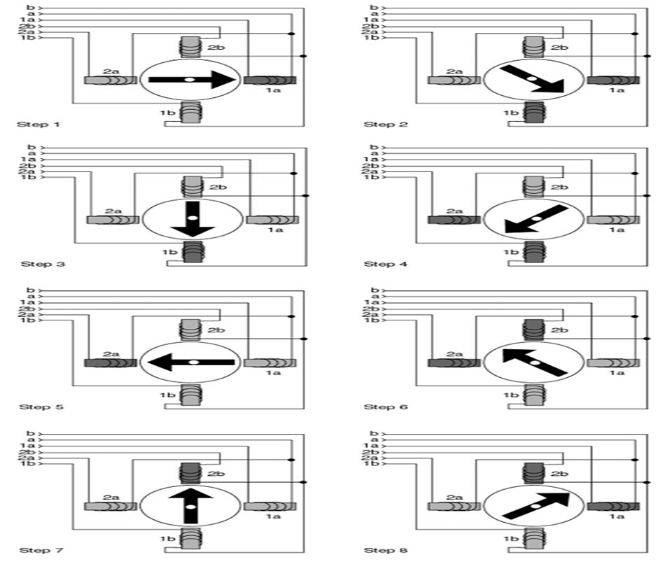
STEPPER MOTORS Stepper Motor is widely used in CNC machine drives, robots, and wherever an accurate positioning is required. In such applications, step angle, direction, operating modes( single coil or double coil), Speed and position are important considerations.
, Speed and position are important considerations..")
16
WHAT IS A STEPPER MOTOR ?? Stepper motor is a simple dc motor with a permanent magnet rotor and a stator with armature consisting of coils. These coils produce a magnetic field when suitable current flows through them this field produces a torque in the rotor which makes it rotate.

17
The step wise motion can be easily controlled by a stepper controller which is a simple circuit which takes digital logic and then uses it to turn the motor step wise. Well these are a little more complicated to control than the simple DC motors but these provide exact step wise rotation with an overall turn of 1.8 degrees / step.

18
Driving Uni polar Stepper Motors Using C51/C251 Introduction Stepper motors are commonly used in accurate motion control. They allow to control any motion with high precision by counting the number of steps applied to the motor.

19
This application note describes how to drive a uni polar stepper motor with the Programmable Counter Array of an Atmel C51/C251 microcontroller Most of systems controlling stepper motors are embedded systems such as printer scanner or floppy disk drive.

20
Identification of Stepper Motor There are several types of stepper motors, these cannot be driven in the same way. In this application note, we have chosen to drive a unipolar stepper motor For more information you will find schemes to identify the other types of stepper motors. Unipolar Stepper Motor Unipolar stepper motors are characterised by their center- tapped windings.

21
Variable Reluctance Variable reluctance stepper motor (also called hybrid motors) are characterized by one common lead.
 are characterized by one common lead.")
22
Driving Uni polar Stepper Motors (ONE PHASE STEPS)
")
23
TWO PHASES ON STEPS

25
SOLAR PANELS AND SOLAR CELLS

26
LM555 Timer : General Description: The LM555 is a highly stable device for generating accurate time delays or oscillation. Additional terminals are provided for triggering or resetting if desired. In the time delay mode of operation, the time is precisely controlled by one external resistor and capacitor. For astable operation as an oscillator,the free running frequency and duty cycle are accurately controlled with two external resistors and one capacitor. The circuit may be triggered and reset on falling waveforms, and the output circuit can source or sink up to 200mA or drive TTL circuits.

27
ASTABLE OPERATION If the circuit is connected as shown in Figure ( pins 2 and 6 Connected ) it will trigger itself and free run as a multivibrator. The external capacitor charges through RA + RB and discharges through RB. Thus the duty cycle may be precisely set by the ratio of these two resistors.

28
A/D CONVERTER Features : Easy interface to all microprocessors Operates ratiometrically or with 5 VDC or analog span adjusted voltage reference No zero or full-scale adjust required 8-channel multiplexer with address logic 0V to 5V input range with single 5V power supply Outputs meet TTL voltage level specifications Standard hermetic or molded 28-pin DIP package 28-pin molded chip carrier package

29
DESCRIPTION The ADC0808, data acquisition component is a monolithic, CMOS device with an 8-bit analog-to-digital converter, 8-channel multiplexer and microprocessor compatible control logic. The 8-bit A/D converter uses successive approximation as the conversion technique. The converter features a high impedance chopper stabilized comparator, a 256R voltage Divider with analog switch tree and a successive approximation register. The 8-channel multiplexer can directly access any of 8-single-ended analog signals.Easy interfacing to Microprocessors is provided by the latched and decoded multiplexer address inputs and latched TTL TRI-STATE® outputs.

30
PIN CONFIGURATION

31
LCD UNIT FEATURES: Interface with either 4-bit or 8-bit microprocessor. Display data RAM (80 characters). Character generator ROM(160 character patterns) Character generator RAM(8 different user programmed patterns)
. Character generator ROM(160 character patterns) Character generator RAM(8 different user programmed patterns).")
32
Display data RAM and character generator RAM may be accessed by the microprocessor. Numerous instructions (Clear Display, Blink Character, Cursor Shift, Display Shift, etc.) Built-in reset circuit is triggered at power ON. Built-in oscillator.
 Built-in reset circuit is triggered at power ON. Built-in oscillator..")
33
SOFTWARE DESCRIPTION: The C programming language is a general – purpose programming language C is not a big language and is not designed for any one particular area of application. Its generality combined with its absence of restrictions makes C a convenient and effective programming solution for a wide variety of software tasks. Many applications can be solved more easily and efficiently with C than with other more specialized languages.

34
The Cx51 Optimizing C Compiler is a complete implementation of the American National Standards Institute (ANSI) standard for the C language. . Cx51 provides you with the flexibility of programming in C and the code efficiency and speed of assembly language. Since Cx51 is a cross compiler standard libraries are altered or enhanced to address the peculiarities of an embedded target processor.

35
SOURCE CODE #include void lcd_string1(unsigned char *); void lcd_string2(unsigned char *); void lcd_command(unsigned char); void lcd_data(unsigned char); void lcd_init(void); void lcd_delaybig(void); void lcd_delaysmall(void);
; void lcd_string2(unsigned char *); void lcd_command(unsigned char); void lcd_data(unsigned char); void lcd_init(void); void lcd_delaybig(void); void lcd_delaysmall(void);")
36
void delay(void); void delayvar(unsigned int); void test(void); void powinit(void); void clkwise(int); void aclkwise(int); void timer0 (void); void dispnum(unsigned char a); unsigned char getadc( void); void scan(void);
; void delayvar(unsigned int); void test(void); void powinit(void); void clkwise(int); void aclkwise(int); void timer0 (void); void dispnum(unsigned char a); unsigned char getadc( void); void scan(void);")
37
void main( void) { powinit(); test(); while(1) { timeout=10000; toutstart=1; while(!toutend); toutend=0; toutstart=0; scan(); }
 { powinit(); test(); while(1) { timeout=10000; toutstart=1; while(!toutend); toutend=0; toutstart=0; scan(); }")
38
//LCD interface functions void lcd_init() { lcd_port=0; RS=0; RW=0; EN=1; EN=0; lcd_delaybig(); lcd_command(0x38); //2 lines & 5x7 matrix lcd_command(0x0e); //Display on, cursor blinking lcd_command(0x01); //Clear display screen lcd_command(0x6); //Shift cursor to right lcd_command(0x80); //Force cursor to beginning of 1st line }
 { lcd_port=0; RS=0; RW=0; EN=1; EN=0; lcd_delaybig(); lcd_command(0x38); //2 lines & 5x7 matrix lcd_command(0x0e); //Display on, cursor blinking lcd_command(0x01); //Clear display screen lcd_command(0x6); //Shift cursor to right lcd_command(0x80); //Force cursor to beginning of 1st line }")
39
void lcd_command(unsigned char command) { lcd_port=command; RS=0; RW=0; EN=1; EN=0; lcd_delaysmall(); } void lcd_data(unsigned char lcddata) { lcd_port=lcddata; RS = 1; RW = 0; EN = 1; EN = 0; lcd_delaysmall(); }
 { lcd_port=command; RS=0; RW=0; EN=1; EN=0; lcd_delaysmall(); } void lcd_data(unsigned char lcddata) { lcd_port=lcddata; RS = 1; RW = 0; EN = 1; EN = 0; lcd_delaysmall(); }")
40
void lcd_string1(unsigned char *p) { unsigned int i; lcd_command(0x80); for(i=0;i<16;i++) lcd_data(' '); lcd_command(0x80); while(*p!=0) { lcd_data(*p); p++; } void lcd_string2(unsigned char *p) { unsigned int i; lcd_command(0xc0); for(i=0;i<16;i++) lcd_data(' '); lcd_command(0xc0); while(*p!=0) { lcd_data(*p); p++; }
 { unsigned int i; lcd_command(0x80); for(i=0;i<16;i++) lcd_data( ); lcd_command(0x80); while(*p!=0) { lcd_data(*p); p++; } void lcd_string2(unsigned char *p) { unsigned int i; lcd_command(0xc0); for(i=0;i<16;i++) lcd_data( ); lcd_command(0xc0); while(*p!=0) { lcd_data(*p); p++; }")
41
void powinit(void) { EA=1; ET0=1; PT0=1; TMOD=1; TL0=0X2F;//2ms at 12 MHz TH0=0XF8; TR0=1; stport=0; adcport=0xff;
 { EA=1; ET0=1; PT0=1; TMOD=1; TL0=0X2F;//2ms at 12 MHz TH0=0XF8; TR0=1; stport=0; adcport=0xff;")
42
SOC=0; EOC=1; ALE=0; //AI=0; //BI=0; //CI=0; toutstart=0; toutend=0; timeout=0; curpos=5; lcd_init(); } void test(void) { lcd_string2("TEST"); clkwise(5); aclkwise(5); }
; } void test(void) { lcd_string2( TEST ); clkwise(5); aclkwise(5); }")
43
void clkwise(int psteps) { unsigned char stval,st; int steps; for(steps=0;steps<(psteps*2);steps++) { stval=0x10; for(st=0;st<4;st++) { stport=stval; stval<<=1; delayvar(9000); }
 { unsigned char stval,st; int steps; for(steps=0;steps<(psteps*2);steps++) { stval=0x10; for(st=0;st<4;st++) { stport=stval; stval<<=1; delayvar(9000); }")
44
void aclkwise(int psteps) { unsigned char stval,st; int steps; for(steps=0;steps<(psteps*2);steps++) { stval=0x80; for(st=0;st<4;st++) { stport=stval; stval>>=1; delayvar(9000); }
 { unsigned char stval,st; int steps; for(steps=0;steps<(psteps*2);steps++) { stval=0x80; for(st=0;st<4;st++) { stport=stval; stval>>=1; delayvar(9000); }")
45
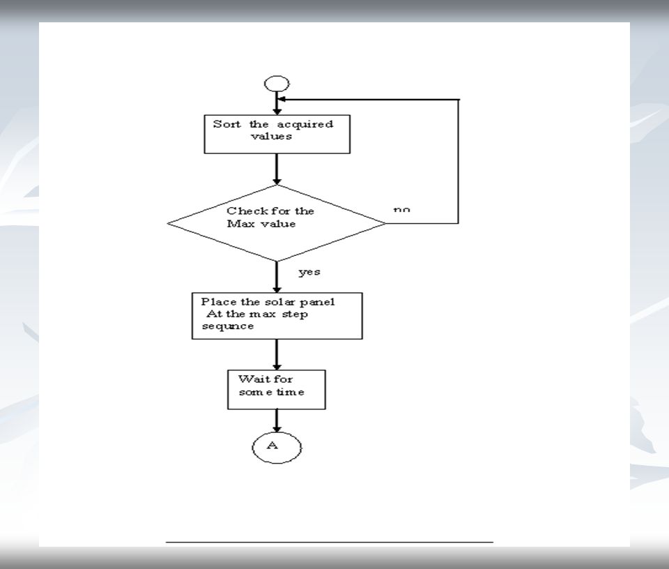
void scan(void) { unsigned char i,maxval,maxpos,temppos; aclkwise(curpos); for(curpos=0;curpos<10;curpos++) { sundata[curpos]=getadc(); clkwise(1); lcd_string1("SCANNING AT"); dispnum(curpos); lcd_string2("VALUE IS "); dispnum(sundata[curpos]); delayvar(0xaaaa); } maxval=sundata[0]; maxpos=0;
![void scan(void) { unsigned char i,maxval,maxpos,temppos; aclkwise(curpos); for(curpos=0;curpos<10;curpos++) { sundata[curpos]=getadc(); clkwise(1); lcd_string1( SCANNING AT ); dispnum(curpos); lcd_string2( VALUE IS ); dispnum(sundata[curpos]); delayvar(0xaaaa); } maxval=sundata[0]; maxpos=0;](http://images.slideplayer.com/12/3593597/slides/slide_45.jpg "void scan(void) { unsigned char i,maxval,maxpos,temppos; aclkwise(curpos); for(curpos=0;curpos<10;curpos++) { sundata[curpos]=getadc(); clkwise(1); lcd_string1( SCANNING AT ); dispnum(curpos); lcd_string2( VALUE IS ); dispnum(sundata[curpos]); delayvar(0xaaaa); } maxval=sundata[0]; maxpos=0;")
46
for(i=1;i<10;i++) { if(maxval<sundata[i]) { maxval=sundata[i]; maxpos=i; } lcd_string1("MAX O/P AT: "); lcd_data(maxpos+48); lcd_string2("MAX O/P V: "); dispnum(maxval); temppos=curpos-maxpos; curpos=maxpos; aclkwise(temppos); }
![for(i=1;i<10;i++) { if(maxval<sundata[i]) { maxval=sundata[i]; maxpos=i; } lcd_string1( MAX O/P AT: ); lcd_data(maxpos+48); lcd_string2( MAX O/P V: ); dispnum(maxval); temppos=curpos-maxpos; curpos=maxpos; aclkwise(temppos); }](http://images.slideplayer.com/12/3593597/slides/slide_46.jpg "for(i=1;i<10;i++) { if(maxval<sundata[i]) { maxval=sundata[i]; maxpos=i; } lcd_string1( MAX O/P AT: ); lcd_data(maxpos+48); lcd_string2( MAX O/P V: ); dispnum(maxval); temppos=curpos-maxpos; curpos=maxpos; aclkwise(temppos); }")
47
FLOW CHART

49
APPLICATIONS Solar tracking system is used in satellites as a source of fuel. It is used in solar thermal collector to collect heat. It is used in solar hot water panel that uses the sun's energy to heat a fluid, which is used to transfer the heat to a heat storage vessel. It is used in water heaters.

50
It is used in heat exchangers. It is used in solar power plants. It is used for desalination of sea water. It is used in inverters (AC to DC). It is used in solar water pumps.
. It is used in solar water pumps..")
51
DRAWBACKS Tracker is affected by temporal variations in the atmospheric refractions caused by rain, cloud, etc. Thus, the system may give an erroneous detection in the direction of the sun, and lead to wrong positioning of the solar panel Thus, the system may give an erroneous detection in the direction of the sun, and lead to wrong positioning of the solar panel.

52
ADVANTAGES The tracking system is not constrained by the geographical location of installation of the solar panel. It is designed for searching the maximum solar irradiance in the whole azimuth and tilt angle. The operator interference is minimal because of not needing to be adjusted.

53
CONCLUSION To collect the greatest amount of energy from the sun, solar panels must be aligned orthogonally to the sun. For this purpose, a new solar tracking technique based on micro-controller was implemented and tested in this study. There are several new solar cell concepts that aim at making better use of the solar spectrum and achieve much higher energy conversion efficiencies

Similar presentations


>")


 SAKTHIDHASAN.S (05ME39) SAKTHIVEL.N (05ME40) VINOTH.S (05ME56) PROJECT GUIDE:>")


 COLLEGE:DIET BRANCH:EC.>")


