Download presentation
Presentation is loading. Please wait.

1
Submitted by:

2
Project overview Block diagram Power supply Microcontroller MAX232 & DB9 Connector Relay Relay driver Software requirements Schematic & Working of the project Advantages Applications Future scope Conclusion

3
This project constitutes external load for home applications controlled with the help of PC. An Embedded project is a combination of hardware and software, designed to perform a specific task. In embedded technology, the embedded programming is burnt into the microcontroller. PC is connected to microcontroller through a level shifter IC, ULN2003 (Driver) is used to drive the relays, and from relays we can connect external devices. MAX-232 is used as voltage level shifter because PC voltage levels and microcontroller voltage levels are different. DB9 (RS-232) connector is used to connect to PC com port. It can also manage a new economical solution of theater light control systems.
 is used to drive the relays, and from relays we can connect external devices. MAX-232 is used as voltage level shifter because PC voltage levels and microcontroller voltage levels are different. DB9 (RS-232) connector is used to connect to PC com port. It can also manage a new economical solution of theater light control systems..")
5
Step down transformer Bridge rectifier Filter Regulator

6
The 230V AC supply is first stepped down to 12V AC using a step down transformer. This is then converted to DC using bridge rectifier. The AC ripples is filtered out by using a capacitor and given to the input pin of voltage regulator 7805. At output pin of this regulator we get a constant 5V DC which is used for MC and other ICs in this project.

7
It is a smaller computer Has on-chip RAM, ROM, I/O ports... RAM ROM I/O Port Timer Serial COM Port Microcontroller CPU A single chip

8
CPU On-chip RAM On-chip ROM for program code 4 I/O Ports Timer 0 Serial Port OSC Interrup t Control External interrupts Timer 1 Timer/Counter Bus Control TxD RxD P0 P1 P2 P3 Address/Data Counter Inputs

9
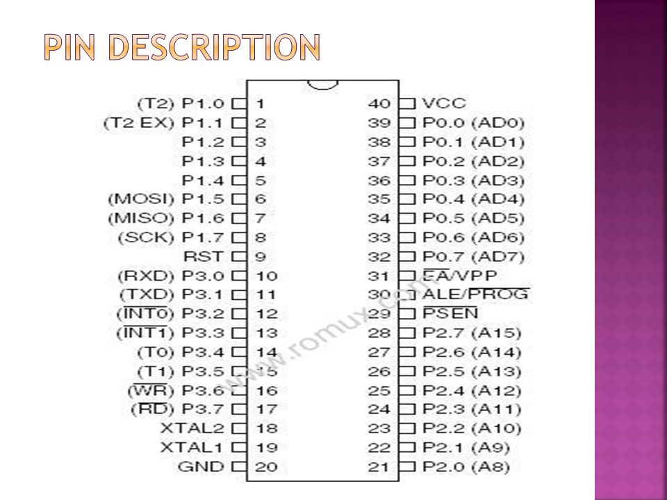
8K Bytes of In-System Programmable (ISP) Flash Memory 4.0V to 5.5V Operating Range Fully Static Operation: 0 Hz to 33 MHz 256 x 8-bit Internal RAM 32 Programmable I/O Lines Three 16-bit Timer/Counters Eight Interrupt Sources Full Duplex UART Serial Channel
 Flash Memory 4.0V to 5.5V Operating Range Fully Static Operation: 0 Hz to 33 MHz 256 x 8-bit Internal RAM 32 Programmable I/O Lines Three 16-bit Timer/Counters Eight Interrupt Sources Full Duplex UART Serial Channel")
11
+5V 30 pF 8.2 K 10 uF + 11.0592 MHz EA/VPP X1 X2 RST 31 19 18 9

12
The MAX232 is an integrated circuit that converts signals from an RS-232serial port to signals suitable for use in TTL compatible digital logic circuits. The MAX232 is a dual driver/receiver and typically converts the RX, TX, CTS and RTS signals. When a MAX232 IC receives a TTL level to convert, it changes a TTL Logic 0 to between +3 and +15V, and changes TTL Logic 1 to between -3 to -15V, and vice versa for converting from RS232 to TTL.

13
The DB9 (originally DE-9) connector is an analog 9-pin plug of the D-Sub miniature connector family.
 connector is an analog 9-pin plug of the D-Sub miniature connector family.")
14
A relay is an electrically operated switch. Current flowing through the coil of the relay creates a magnetic field which attracts a lever and changes the switch contacts. The coil current can be on or off so relays have two switch positions and have double throw (changeover) switch contacts as shown in the diagram.
 switch contacts as shown in the diagram..")
15
Relays allow one circuit to switch a second circuit which can be completely separate from the first. For example a low voltage battery circuit can use a relay to switch a 230V AC mains circuit. There is no electrical connection inside the relay between the two circuits, the link is magnetic and mechanical. To drive relay through MC ULN2003 relay driver IC is used

16
ULN is Relay driver application The ULN2003 is a monolithic high voltage and high current Darlington transistor arrays. It consists of seven NPN Darlington pairs that features high-voltage outputs with common- cathode clamp diode for switching inductive loads. The collector-current rating of a single Darlington pair is 500mA. The Darlington pairs may be paralleled for higher current capability.

17
The ULN functions as an inverter. If the logic at input 1B is high then the output at its corresponding pin 1C will be low.

18
Keil an ARM Company makes C compilers, macro assemblers, real-time kernels, debuggers, simulators, integrated environments, evaluation boards, and emulators for ARM7/ARM9/Cortex-M3, XC16x/C16x/ST10, 251, and 8051 MCU families. Compilers are programs used to convert a High Level Language to object code. Desktop compilers produce an output object code for the underlying microprocessor, but not for other microprocessors.

19
i.e the programs written in one of the HLL like ‘C’ will compile the code to run on the system for a particular processor like x86 (underlying microprocessor in the computer). For example compilers for Dos platform is different from the Compilers for Unix platform So if one wants to define a compiler then compiler is a program that translates source code into object code.

20
The project uses a PC to control the loads. The commands are received by the micro controller through level shifted IC Max232. When the program is executed, it drives relay from the microcontroller through relay driver IC ULN2003. Load’s are switched ON and switched OFF based on the corresponding command sent from the keyboard through hyperterminal. As per the program, the loads will be turned ON and OFF through the relays.

Similar presentations