Download presentation
Presentation is loading. Please wait.

1
FAA Mix Design Presented by Christopher M. Brower
Based on Section 2, Design of Bituminous Paving Mixtures, Job Mix Formula Marshall Methods From the FAA’s Eastern Region Laboratory Procedures Manual (March 2008) Presented by Christopher M. Brower Advance Testing Company, Inc.
 Presented by Christopher M. Brower. Advance Testing Company, Inc.")
2
Overview Aggregate Pre-Qualification Testing
Volumetric Mix Design Procedures Dry Batching Aggregates Mixing Specimens HMA Testing (Bulk, Rice, Stability & Flow) Analysis of Marshall Curves Anti-Stripping Test ddd
 Analysis of Marshall Curves. Anti-Stripping Test. ddd.")
3
Introduction P 401 hot mix asphalt design used during airport construction Mix Design Methodology: Asphalt Institute MS-2, Mix Design Methods (Best Source) Material requirements for the P 401 mixture will be listed in the contract specifications and are determined by the engineer The JMF developed by the contractor is prepared on standard forms (Appendix A)
 Material requirements for the P 401 mixture will be listed in the contract specifications and are determined by the engineer. The JMF developed by the contractor is prepared on standard forms (Appendix A)")
4
Summary of FAA Mix Design
Aggregates properties are tested (soundness, abrasion, crush count, liquid limit, plasticity index, sand equivalence) and must be acceptable in accordance with requirements Aggregate blends are developed that fall within the general limits established, blends are plotted on a power 0.45 curve Batches of the proposed aggregate blend are prepared, three to five specimens are used for each asphalt content for bulk analysis, another two need to be batched for maximum theoretical specific gravity analysis
 and must be acceptable in accordance with requirements. Aggregate blends are developed that fall within the general limits established, blends are plotted on a power 0.45 curve. Batches of the proposed aggregate blend are prepared, three to five specimens are used for each asphalt content for bulk analysis, another two need to be batched for maximum theoretical specific gravity analysis.")
5
Summary of FAA Mix Design
5 asphalt contents will be prepared, each differing by 0.5%, with the intention of bridging the optimum asphalt content Bulk specific gravity and maximum theoretical specific gravities are measured for each asphalt content, volumetric properties are derived through calculation Stability and flow properties are tested and measured

6
Summary of FAA Mix Design
Volumetric properties and stability and flow measurements are plotted against asphalt content Optimum asphalt content is chosen from plots and verified with additional batches TSR testing is performed at the optimum asphalt content

20
Preliminary Procedures
Aggregate properties determined as per Appendix A JMF is developed using either plant bins or stockpiles (hot bins are highly recommended at a batch plant)
")
22
Wear-Abrasion (ASTM C 131)
Measures the resistance to wearing as aggregate is subjected to impact and grinding Ensures that aggregate will not wear excessively during shipment and production Standard graded aggregate is subjected to impact and grinding by steel spheres inside a hollow steel chamber

23
Wear-Abrasion (ASTM C 131)
A small shelf lifts the aggregate and steel spheres and as the chamber rotates, creating the impact The wear value is a measurement of the percent of loss (by mass) of the sample after it has been subjected to a specified number of revolutions in the chamber
 of the sample after it has been subjected to a specified number of revolutions in the chamber.")
24
Wear-Abrasion (ASTM C 131)
This loss is measured over the 1.7 mm (#12) sieve Appendix A stipulates maximum 40% wear for surface courses maximum 50% wear for base courses
 sieve. Appendix A stipulates maximum 40% wear for surface courses maximum 50% wear for base courses.")
25
Soundness (ASTM C 88) The soundness test subjects aggregate particles to alternating cycles of soaking in a salt solution (either sodium or magnesium sulfate) and drying in an oven regulated at 110±5˚C (230±9˚F) Salts permeate the voids of the aggregate during soaking and expand during drying, simulating the expansive pressures of water
 and drying in an oven regulated at 110±5˚C (230±9˚F) Salts permeate the voids of the aggregate during soaking and expand during drying, simulating the expansive pressures of water.")
26
Soundness (ASTM C 88) The soundness value is also a measure of loss of particles after the sample has been subjected to a specified number of soaking and drying cycles Appendix A stipulates the maximum loss as 10% for sodium sulfate tests and 13% for magnesium sulfate tests

27
Flat & Elongated (ASTM D 4791)
Flat and elongated particles in an aggregate are measured using a proportional caliper device set to the appropriate ratios required by the agency Flat AND elongated test: length to thickness is compared

28
Flat & Elongated (ASTM D 4791)
Flat or elongated particles in an HMA mixture may degrade more quickly than non flat or elongated particles, thereby reducing the durability of the pavement Appendix A limits the amount of these particles in the coarse aggregate to no more than 8% at a 5:1 ratio and no more than 20% at a 3:1 ratio

29
Crushed Pieces In order to produce pavements that are resistant to deformation, it helps to use angular aggregate particles Angular aggregates tend to interlock and resist deformation even after repeated loading The crushed pieces requirement in Appendix A is meant to ensure the aggregate angularity is maintained

30
Crushed Pieces FAA Eastern Region Lab Procedures indicate that a fractured face “shall be equal to at least 75% of the smallest mid-sectional area of the piece” When two fractured faces are contiguous, the angle between the planes of fractures shall be at least 30 degrees to count as two fractured faces Fractured faces shall be obtained by crushing

31
Crushed Pieces Requirements for crushed pieces in coarse aggregate are dependent upon anticipated loading of pavement

32
Slag Density (ASTM C 29) The use of air cooled blast furnace slag as an aggregate item (where available and when desired) may be allowed
 The use of air cooled blast furnace slag as an aggregate item (where available and when desired) may be allowed.")
33
Liquid Limit (ASTM D 4318) The liquid limit test measures the water content of a material at the point it passes from a solid to a liquid state This test is used in conjunction with the plastic limit test to determine the plasticity index

34
Plasticity Index (ASTM D 4318)
The plasticity index is a measure of the range of moisture contents that a sample will act in a plastic fashion but not in a liquid fashion Generally used with cohesive soils, this procedure is used on fine aggregates proposed for use in HMA to ensure that they exhibit minimal plasticity

35
Plasticity Index (ASTM D 4318)
A fine aggregate with plasticity index of greater than 6 would indicate an aggregate with an excessive amount of cohesive fines These cohesive fines might weaken the bond between the liquid binder and the aggregate particles, decreasing the durability of the HMA mixture When mineral filler is used in the HMA mixture, a plasticity test is also required

36
Sand Equivalent (ASTM D 2419)
The sand equivalent value is a measure of the relative amount of fines in the fine aggregate sample This is performed by placing the fines in suspension in a solution of calcium chloride above the sand

37
Sand Equivalent (ASTM D 2419)
The sand equivalent value itself is an expression of the sand reading in terms of the clay reading Higher sand equivalent values therefore mean less clay like fines Appendix A requires at least 45% for sand equivalent

38
Specific Gravity of Coarse Aggregates (ASTM C 127)
Specific gravity of coarse aggregate is performed in the lab on samples that have soaked for 24±4 hours in water at room temperature Of particular interest to the HMA designer is the measurement of the stone’s bulk specific gravity, Gsb

39
Bulk Specific Gravity of Coarse Aggregates (ASTM C 127)
The bulk specific gravity uses the bulk volume of the aggregate particle, which includes the volume of pore space within the particle occupied by water This requires that the mass of the particles used for the volumetric measurement is determined in an SSD (saturated, surface dry) condition
 condition.")
40
Specific Gravity of Fine Aggregates (ASTM C 128)
The specific gravity of the fine aggregate needs to be determined as well This method uses a glass pycnometer of a known volume to determine the water displaced by the sample

41
Specific Gravity of Fine Aggregates (ASTM C 128)
The bulk specific gravity (Gsb) of the fine aggregate is also measured at an SSD condition The SSD condition of the sand is often discerned using an inverted cone with a tamper
 of the fine aggregate is also measured at an SSD condition. The SSD condition of the sand is often discerned using an inverted cone with a tamper.")
42
Combined Bulk Specific Gravity
The bulk gravities of the combined aggregates in the mixture have a significant effect on the overall density of the mixture The combined bulk gravity of all constituents, based on their percentage in the blend, is used to calculate VMA (Voids in Mineral Aggregate) ddd
 ddd.")
43
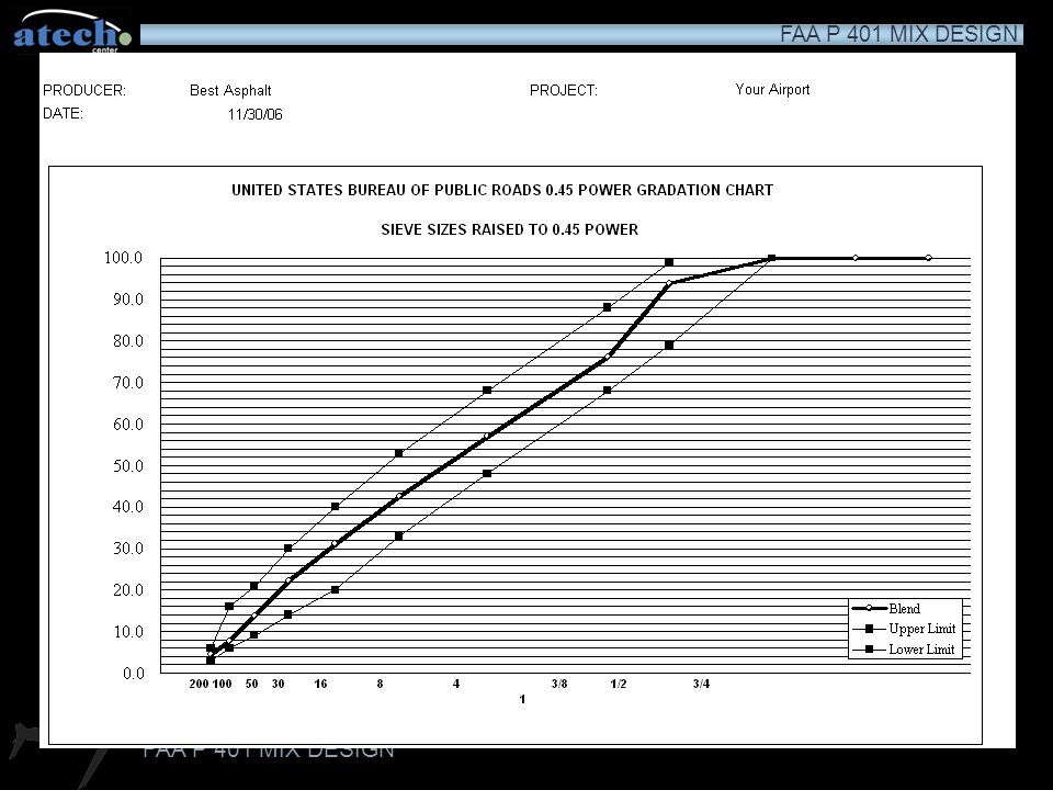
Aggregate Gradation Requirements
Proposed combined gradation (particle distribution) is plotted on a 0.45 power gradation chart Grading curve must closely parallel the curves for the upper and lower JMF limits Grading curve should display no abrupt changes
 is plotted on a 0.45 power gradation chart. Grading curve must closely parallel the curves for the upper and lower JMF limits. Grading curve should display no abrupt changes.")
44
ddd

45
Volumetric Mix Design Overview
Must prepare lab specimens for bulk analysis (Gmb)and loose mix samples for theoretical density (Gmm) over a range of asphalt contents for testing Minimum of three bulk specimens per asphalt content (4 recommended) Typically five or six different asphalt contents (separated by 1/2 %) are used Design must display two asphalt contents above “optimum”, and two below optimum
and loose mix samples for theoretical density (Gmm) over a range of asphalt contents for testing. Minimum of three bulk specimens per asphalt content (4 recommended) Typically five or six different asphalt contents (separated by 1/2 %) are used. Design must display two asphalt contents above optimum , and two below optimum.")
46
Volumetric Mix Design Overview
Test results on each of the blends are plotted graphically to show physical properties Optimum asphalt content is selected from graphical representations of test data Mix properties plotted against asphalt content as part of volumetric mix design method

47
Mixing Equipment Pans, metal, flat bottom for the heating of test specimens Oven and hot plate for heating asphalt and aggregate to required temperatures

48
Mixing Equipment Mixing bowl, round, approx. 4 liter capacity for mixing asphalt & aggregate Scoop, for batching aggregates

49
Mixing Equipment Container for heating asphalt (hopper with control valve recommended) Thermometers, armored glass, or metal stem (50 to 450˚ F with sensitivity of 5.0˚ F) for determining temperature of aggregate, asphalt, and asphalt mixture Balance, 4.5Kg capacity, sensitive to 0.5g for weighing aggregates and asphalt
 for determining temperature of aggregate, asphalt, and asphalt mixture. Balance, 4.5Kg capacity, sensitive to 0.5g for weighing aggregates and asphalt.")
50
Mixing Equipment Mixing spoons, spatulas, and rodding implement
Mechanical shaker for sieves Large spatula for spading and hand mixing Mixing apparatus, mechanical recommended, commercial bread dough mixer with 4 liter (4 quart) capacity or larger with two metal mixing bowls and two wire stirrers
 capacity or larger with two metal mixing bowls and two wire stirrers.")
51
Compaction Pedestal 8” x 8” x 8” wooden post capped with a 12” x 12” x 1” steel plate Wooden post: oak, yellow pine, or other wood with dry unit weight of 42 to 48 pcf Wooden post secured by four angle brackets to a solid concrete slab Steel plate firmly fastened to post (no movement at all) Pedestal installed level, post is plumb, and no movement during compaction process
 Pedestal installed level, post is plumb, and no movement during compaction process.")
52
Compaction Mold Base plate, forming mold, and collar
Forming mold has inside diameter of 4 inches and height of 3 inches

53
Compaction Hammer Flat circular tamping face, 3 7/8 inches (98.4mm diameter) 10 lb (4.5 kg) weight 18” (457 mm) drop of hammer onto specimen Spring tension device to hold compaction mold in place on compaction pedestal
 drop of hammer onto specimen. Spring tension device to hold compaction mold in place on compaction pedestal.")
54
Equipment Extrusion jack, for extruding compacted specimen from mold
Gloves, insulated, for handling hot equipment Marking crayons for labeling specimens

55
Aggregate Batching Prepare at least 3 but no more than 5 batches for each asphalt content Aggregates in batches shall be dried to constant mass at 221 to 230˚F (105 to 110˚C) and separated by dry-sieving into the desired fractions Aggregate batches consist of the proposed blend of aggregates to be used in the HMA
 and separated by dry-sieving into the desired fractions. Aggregate batches consist of the proposed blend of aggregates to be used in the HMA.")
56
Aggregate Batching Each particle size for each aggregate constituent is placed into each batch The size of the batches (around 1200 g) is intended (when mixed with the liquid binder) to produce bulk specimens that are 2.5±0.5 inches in height
 is intended (when mixed with the liquid binder) to produce bulk specimens that are 2.5±0.5 inches in height.")
57
Material Heating Aggregate is placed into an oven regulated 50˚F (20˚C) higher than the mixing temperature Liquid binder should be heated to the mixing temperature (not more than 1 hour prior to mixing) and covered Mixing should not begin until the aggregate and liquid binder have stabilized at the appropriate temperature
 and covered. Mixing should not begin until the aggregate and liquid binder have stabilized at the appropriate temperature.")
58
Mixing & Compaction Temperatures
Mixing and compaction temperatures determined by the temperature viscosity chart Mixing temperature is defined as that range of temperatures that produces a viscosity of 0.17±0.02 kPa (170±20 centistokes) in the liquid binder (asphalt cement) Compaction temperature is defined as that range of temperatures that produces a viscosity of 0.28±0.03 kPa (280±30 centistokes) in the liquid binder (asphalt cement)
 in the liquid binder (asphalt cement) Compaction temperature is defined as that range of temperatures that produces a viscosity of 0.28±0.03 kPa (280±30 centistokes) in the liquid binder (asphalt cement)")
59
Temperature/Viscosity Chart

60
Preparation of Molds/Hammer
Thoroughly clean the specimen mold assembly and the face of the compaction hammer Heat them on a hot plate (or in boiling water) to a temperature between 200–300˚F (93-149˚C) Use a protection disk in the bottom of each mold prior to charging the mold with HMA
 to a temperature between 200–300˚F (93-149˚C) Use a protection disk in the bottom of each mold prior to charging the mold with HMA.")
61
Mixing HMA Keep all materials up to temperature as much as possible
A hot plate may be used to keep the mixing bowl warm, however heat should be baffled to prevent localized overheating Charge heated bowl with aggregates, dry mix thoroughly

62
Mixing HMA Form a crater in the dry aggregate
Weigh out the appropriate mass of liquid binder (asphalt cement) into the batch in accordance with accumulated batch weights Mix HMA with mechanical mixer or by hand as quickly and thoroughly as possible Mix HMA so that liquid binder coverage is uniform
 into the batch in accordance with accumulated batch weights. Mix HMA with mechanical mixer or by hand as quickly and thoroughly as possible. Mix HMA so that liquid binder coverage is uniform.")
63
Compacting Specimens Charge the specimen mold with the mixture

64
Compacting Specimens Spade the mixture vigorously with a heated trowel or spatula 15 times around the exterior and 10 times over the interior of the specimen

65
Compacting Specimens Remove the specimen mold collar and smooth the surface of the sample to a slightly rounded shape

66
Compacting Specimens Determine the temperature of the sample, it should be within the compaction temperature range If the specimen is cold, it shall be discarded; reheating is not allowed

67
Compacting Specimens Replace collar on mold, place protection disk on top of specimen Place hammer apparatus into mold, apply appropriate number of blows (50 or 75, as indicated in contract specifications) Turn specimen over to compact the other side
 Turn specimen over to compact the other side.")
68
Compacting Specimens When compaction is completed, remove specimen from apparatus, remove protection disks, and allow it to cool

69
Compacting Specimens Cool long enough so that when it is extruded with the specimen extruder no deformation will result

70
Test Procedure Each compacted specimen is subjected to a bulk test, stability and flow test, and voids analysis Two maximum theoretical specific gravity samples are prepared and tested at each asphalt content in order to determine the void level of the bulk specimen

71
Bulk Test Equipment Balance, 2 kg. minimum capacity, sensitive to 0.1g, to enable bulk specific gravity samples to be calculated to at least 4 significant figures Balance should be equipped with suspension apparatus to permit weighing specimen in water Water bucket, suitable for weighing bulk specimen (equipped with overflow outlet) Thermometers, for bulk test/rice test water batch to verify 77˚F (25˚C)
 Thermometers, for bulk test/rice test water batch to verify 77˚F (25˚C)")
72
Bulk Specific Gravity (Gmb) ASTM D 2726
Care should be taken to avoid distortion of specimen when removing from mold Specimens shall be free of foreign materials prior to testing Determine the mass of the specimen after it has been standing in air at room temperature for at least one hour, designate as mass A ddd

73
Bulk Specific Gravity (Gmb) ASTM D 2726
Immerse the specimen in a water bath at 77±1.8˚F (25±1˚C) for 3 to 5 minutes Maintain proper water level on weigh below apparatus with overflow outlet
 for 3 to 5 minutes. Maintain proper water level on weigh below apparatus with overflow outlet.")
74
Bulk Specific Gravity (Gmb) ASTM D 2726
Record mass of immersed specimen as C mass

75
Bulk Specific Gravity (Gmb) ASTM D 2726
Remove the specimen from the bath and quickly blot specimen with a damp towel (remove surface moisture of specimen, but leave internal moisture) Record mass of SSD (saturated, surface dry) specimen as C Bulk specific gravity (Gmb) = A/(B–C) Report Gmb to nearest 0.001
 Record mass of SSD (saturated, surface dry) specimen as C. Bulk specific gravity (Gmb) = A/(B–C) Report Gmb to nearest")
76
Stability & Flow Equipment
Marshall stability press, electric powered and designed to apply loads to test specimens through semicircular testing heads at a constant rate of 2 inches (51 mm) per minute Equipped with proving ring for determining applied force load Stability testing head assembly Flow meter for determining the amount of deformation at maximum load
 per minute. Equipped with proving ring for determining applied force load. Stability testing head assembly. Flow meter for determining the amount of deformation at maximum load.")
77
Stability & Flow Equipment
Testing machine may have automatic plotting function Stability & Flow Equipment Water bath, at least 6 inches deep and thermostatically controlled to 140˚±1.8˚F (60±1˚C), with perforated false bottom 2 inches above bath bottom Thermometers, for hot stability bath with a range of ˚F (57-62˚C)
, with perforated false bottom 2 inches above bath bottom. Thermometers, for hot stability bath with a range of ˚F (57-62˚C)")
78
Stability & Flow Testing
Immerse the specimens in water bath at 140±1.8˚F (60±1˚C) for 30 to 40 minutes prior to testing Clean inside surfaces of testing heads, maintain temperature of testing heads at ˚F (21-38˚C) Lubricate guide rods on testing head so that they move freely Check that proving ring dial is zeroed properly Check that flow meter is zeroed properly
 for 30 to 40 minutes prior to testing. Clean inside surfaces of testing heads, maintain temperature of testing heads at ˚F (21-38˚C) Lubricate guide rods on testing head so that they move freely. Check that proving ring dial is zeroed properly. Check that flow meter is zeroed properly.")
79
Stability & Flow Testing
With everything in readiness, remove specimen from hot bath, dry surface, and place on lower testing head Make sure specimen is aligned and centered in testing head properly Place upper testing head on specimen, fit entire assembly into stability press Place flow meter on forward guide rod and adjust to zero as necessary

80
Stability & Flow Testing
Begin to apply load to specimen at rate of 2 inches per minute Observe stability press dial during loading, keep flow meter in position Watch stability dial for peak load and record The instant the stability dial begins to decrease remove the flow meter from the guide rod ddd

81
Stability & Flow Testing
Record the flow reading as a whole number, i.e. 15, but recall this means that the deformation of the specimen was 0.15 inches This specification requires that the stability and flow readings must be obtained within 30 seconds after removal of the specimen from the hot water bath

82
Stability & Flow Testing
If an automatic plot was produced by the device, record the peak load and flow from the peak of the curve

83
Stability & Flow Testing
If a manual device was used, the stability dial reading may need to be converted to a pounds of force measurement based on a machine specific conversion chart This measured stability may also need to be corrected based on its height or volume The measured stability is multiplied by a correlation ratio derived from the Stability Correlation Ratio table in order to determine the corrected stability

84
Maximum Theoretical Specific Gravity (ASTM D 2041)
The maximum theoretical specific gravity is the ratio of the mass of a given volume of separated and cooled hot mix asphalt at 25˚C (77˚F) to the mass of an equal volume of water at the same temperature
 to the mass of an equal volume of water at the same temperature.")
85
Maximum Theoretical Specific Gravity (ASTM D 2041)
The sample is subjected to a partial vacuum (required to be 3.7 ± 0.3 kPa (25.5 to 30 mm Hg) for 15±2 minutes) in order to remove the air trapped between the particles of the sample
 for 15±2 minutes) in order to remove the air trapped between the particles of the sample.")
86
Maximum Theoretical Specific Gravity (ASTM D 2041)
This mass to volume measurement expresses the density of the mixture as if it had no air voids. The maximum Specific Gravity (Gmm) is used in conjunction with Bulk Specific Gravity (Gmb) to determine Percent Air Voids (Pa) in compacted bituminous materials
 is used in conjunction with Bulk Specific Gravity (Gmb) to determine Percent Air Voids (Pa) in compacted bituminous materials.")
87
Density and Voids Analysis
Average the bulk specific gravity values (Gmb) for all test specimens of a given asphalt content Values obviously in error shall not be included in the average (consult ASTM D 2726 for advice on outliers) Determine the unit weight for each average Gmb by multiplying the Gmb by 62.4 for pcf or 1000 for kg/m3
 for all test specimens of a given asphalt content. Values obviously in error shall not be included in the average (consult ASTM D 2726 for advice on outliers) Determine the unit weight for each average Gmb by multiplying the Gmb by 62.4 for pcf or 1000 for kg/m3.")
88
Air Void (Pa) Calculation
Air Voids (Pa) are determined using the following formula: Pa = 100– [100(Gmb/Gmm)]
 are determined using the following formula: Pa = 100– [100(Gmb/Gmm)]")
89
Air Void (Pa) Calculation
Gmb = 2.334 Gmm = 2.416 Pa = [100(2.334/2.416)] Pa = (100 x ) Pa = Pa = 3.39
] Pa = (100 x ) Pa = Pa =")
90
VMA (Voids in Mineral Aggregate) Calculation
VMA is determined using the following formula: VMA= 100 – [(GmbxPs)/Gsb]
/Gsb]")
91
VMA (Voids in Mineral Aggregate) Calculation
Gmb = 2.344 Ps = 93.04 Gsb = 2.651 VMA = [(2.344 x 93.04)/2.651] VMA = (218.1/2.651) VMA = VMA = 17.74
/2.651] VMA = (218.1/2.651) VMA = VMA =")
94
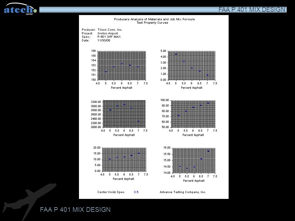
Preparation of Graphs Create a graphical plot for each of the following: Stability (corrected) vs. Asphalt content Flow vs. Asphalt Content Unit weight vs. Asphalt Content Percent air voids vs. Asphalt Content Percent VMA vs. Asphalt Content For each plot connect the values with a smooth curve that best fits all values

95
Test Property Aircraft Gross Weight Aircraft Gross Weight ≥60,000 lbs <60,000 lbs Number of Blows 75 50 Stability, minimum 2150 (9564) 1350 (6005) pounds (newtons) Flow range, 0.01 in 10-14 10-18 (0.25 mm) Air Voids, percent Percent VMA, Dependent on maximum particle size of HMA minimum mixture, see below 1/2 in (12.5 mm) 16 maximum size 3/4 in (19.0 mm) 15 maximum size 1 in (25.0 mm) 14 maximum size 1 1/4 in (31.25 mm) 13 maximum size
 1350 (6005) pounds (newtons) Flow range, 0.01 in (0.25 mm) Air Voids, percent Percent VMA, Dependent on maximum particle size of HMA. minimum. mixture, see below. 1/2 in (12.5 mm) 16. maximum size. 3/4 in (19.0 mm) 15. maximum size. 1 in (25.0 mm) 14. maximum size. 1 1/4 in (31.25 mm) 13. maximum size.")
96
Analysis of Graphs Optimum asphalt content is determined as the asphalt content that produces a void level in the HMA at the mid point of the specified range (2.8 to 4.2 percent air) If the other plotted values do not meet the required criteria, or are marginal, or if the mixture meets parameters but is not compactable in the field, the aggregate blend must be revised or a new source of aggregates secured and a new JMF developed
 If the other plotted values do not meet the required criteria, or are marginal, or if the mixture meets parameters but is not compactable in the field, the aggregate blend must be revised or a new source of aggregates secured and a new JMF developed.")
97
5.1 4.8 5.4

98
Verification of JMF When the selected optimum asphalt content does not coincide with the asphalt content used in the trial specimens, and additional set of specimens shall be prepared The optimum asphalt content is added to the specimens and they are tested as described to verify the actual results duplicate those anticipated from the curves

99
TSR (Tensile Strength Ratio)
Once the optimum asphalt content has been determined and verified, samples need to be prepared and tested for moisture sensitivity and the potential for stripping These tendencies can be gauged using ASTM D 4867, Standard Test for Effect of Moisture on Asphalt Concrete Paving Mixtures, other wise known as the TSR (Tensile Strength Ratio) test
 test.")
100
TSR (Tensile Strength Ratio)
This procedure subjects samples specially prepared at specific void level, saturated with water under vacuum, and “tortured” with some combination of hot water exposure (140˚F for 24 hrs) and possibly freeze/thaw cycles (see Note 5 in ASTM)
 and possibly freeze/thaw cycles (see Note 5 in ASTM)")
101
TSR (Tensile Strength Ratio)
Using a set of specimens as a control, the tortured specimen’s ability to withstand cracking in a special TSR head used in the stability press is compared to the non-tortured specimens This number (TSR) is required by the FAA to be at least 75% (that is, the tortured specimens must have at least 75% of the tensile strength as the non-tortured specimens)
 is required by the FAA to be at least 75% (that is, the tortured specimens must have at least 75% of the tensile strength as the non-tortured specimens)")
102
TSR (Tensile Strength Ratio)
In addition, the surface of the specimens is examined for any evidence of asphalt cement stripping from the surface of the aggregates If the mixture fails this procedure, anti-stripping agent needs to be added to the mixture to produce the desired result

103
Thank You for Your Attention !

Similar presentations


>")


 Prepared by: Dr. Salah Al-Dulaijan.>")


