Download presentation
Presentation is loading. Please wait.

1
Internet Multicast Routing group addressing class D IP addresses link layer multicast two protocol functions group management –IGMP route establishment –DVMRP, MOSPF, CBT, PIM 1110 Multicast Group ID 28 bits

2
Joining a mcast group: two-step process local: host informs local mcast router of desire to join group: IGMP wide area: local router interacts with other routers to receive mcast packet flow many protocols (e.g., DVMRP, MOSPF, PIM)
")
3
IGMP: Internet Group Management Protocol host: sends IGMP report when application joins mcast group IP_ADD_MEMBERSHIP socket option host need not explicitly “unjoin” group when leaving router: sends IGMP query at regular intervals host belonging to a mcast group must reply to query

4
IGMPv1 and v2 IGMPv1 joining host send IGMP report leaving host does nothing router periodically polls hosts on subnet using IGMP Query hosts respond to Query in a randomized fashion IGMPv2 additions: Group Specific Queries Leave Group Message host sends Leave Group message if it was the one to respond to most recent query router receiving Leave Group msg queries group.

5
IGMPv3 unclear status?? additions: Group-Source Specific Queries, Reports and Leaves inclusion/exclusion of sources

6
Protocol Independent Multicast Motivation: DVMRP good for dense group membership need shared/source-based tree flexibility independence from unicast routing Two PIM modes: Dense Mode (approx. DVMRP) Sparse Mode
 Sparse Mode.")
7
PIM- Dense Mode independent from underlying unicast routing slight efficiency cost contains protocol mechanisms to: detect leaf routers avoid packet duplicates

8
PIM - Sparse Mode Rendezvous Point (Core): receivers meet sources reception through RP connection = Shared Tree establish path to source = Source-Based Tree
: receivers meet sources reception through RP connection = Shared Tree establish path to source = Source-Based Tree")
9
PIM - Sparse Mode ReceiverSourceRendez-VousPoint Register Join SourceJoin Prune

10
ReceiverSourceRendez-VousPoint

11
Border Gateway Multicast Routing Protocol (BGMRP) a protocol for inter-domain multicast routing bi-directional shared tree for inter-domain routing cores (RPs) associated with domains receiver domains can utilize choice of protocol
 a protocol for inter-domain multicast routing bi-directional shared tree for inter-domain routing cores (RPs) associated with domains receiver domains can utilize choice of protocol")
12
ICMP: Internet Message Control Protocol used to communicate network-level error conditions and info to IP/TCP/UDP protocols or user processes often considered part of IP, but ICMP message sent within IP datagram IP demultiplexes up to ICMP using IP protocol field ICMP message contains IP header and first 8 bytes of IP contents that causes ICMP mesage to be generated

13
ICMP Packet Types

14
IPv6: next generation IP Changes to Ipv4: 128 bit addresses (so we don't run out of IP addresses) header simplification (faster processing) more support for type of service priorities flow identifier: identifiy packets in a connection security Notes: no fragmentation in network packet too big generates ICMP error to source source fragmentation via extension header no checksum (already done at transport and data link layer)
 header simplification (faster processing) more support for type of service priorities flow identifier: identifiy packets in a connection security Notes: no fragmentation in network packet too big generates ICMP error to source source fragmentation via extension header no checksum (already done at transport and data link layer)")
16
Transitioning from IPv4 to IPv6 Internet too big for "flag day": can't turn off all IP routers, install IPv6 and reboot IPv4 nodes will be legacy IPv6 nodes can route IPv4 packets IPv4 nodes cannot route IPv6 packets

17
Tunneling source and destination speak network protocol X physically intermediate nodes speak network protocol Y source takes protocol X packet, sticks it inside (encapsulates) protocol Y packet intermediate nodes route using protocol Y destination receives packet using protocol Y, removes protocol X packet network between source and destination looks like a single link to protocol X
 protocol Y packet intermediate nodes route using protocol Y destination receives packet using protocol Y, removes protocol X packet network between source and destination looks like a single link to protocol X")
18
Tunneling: a pictorial view

19
Mbone: Multicast Backbone MBONE tunnel endpoint IP router WS virtual network overlaying Internet needed until multicast capable routers deployed and turned on IP in IP encapsulation limited capacity, resilience

20
Case Study: ATM Network Layer ATM: packet (cell) format: UNI: user-network interface (host-to-switch) NNI: network-network interface (switch-to-switch)
 format: UNI: user-network interface (host-to-switch) NNI: network-network interface (switch-to-switch)")
21
GFC: generic flow control (unused) VPI: virtual path identifier VCI: virtual circuit identifier VPI and VCI together a call/connection identifier PTI: payload type: 3 bits 111: RM cell (recall RM congestion control) 000: user cell 010: user cell, congestion experienced (recall EFCI) CLP: cell loss priority (1 bit) priority bit for discarding HEC: header error correction DATA: 48 bytes of data
 VPI: virtual path identifier VCI: virtual circuit identifier VPI and VCI together a call/connection identifier PTI: payload type: 3 bits 111: RM cell (recall RM congestion control) 000: user cell 010: user cell, congestion experienced (recall EFCI) CLP: cell loss priority (1 bit) priority bit for discarding HEC: header error correction DATA: 48 bytes of data")
22
Observations about ATM Cell very small reflecting telephony origins 48 bytes a compromise, halfway 64 and 32 no explicit source/destination address VCI/VPI used instead faster switching (VPI/VCI can index into table) 28 bit VPI/VCI for switching instead of 128 bit IP address in IPv6 (savings) fixed length for faster switching minimal priority
 28 bit VPI/VCI for switching instead of 128 bit IP address in IPv6 (savings) fixed length for faster switching minimal priority")
23
ATM networks: Virtual-circuit Oriented VCI/VPI together identify call multiple calls (VCI) bundled into same VP network can switch on VP basis only less state (network only sees VP's) all VC's in VP follow same path
 bundled into same VP network can switch on VP basis only less state (network only sees VP s) all VC s in VP follow same path")
24
Connection Setup in ATM messages ("signaling") used to setup up call through network state info (VP switching info - which output line to switch incoming VC) set up in switches meaning of call setup messages:
 used to setup up call through network state info (VP switching info - which output line to switch incoming VC) set up in switches meaning of call setup messages:")
26
ATM Call Setup (cont) Observations: unlike Internet, switches involved in call setup state creation ACKing between switches wait one RTT before sending data unlike UDP same as TCP what if connection breaks? other switches must remove state ATM standard does not specify a routing protocol

28
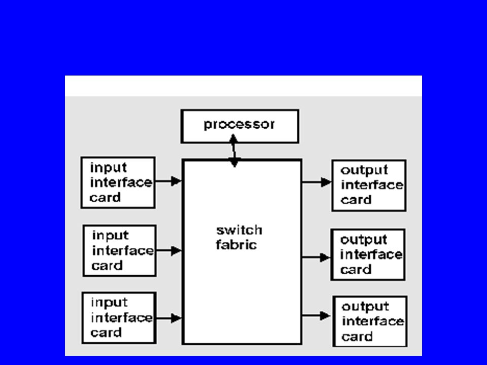
Switches and Routers: What's Inside Input interface cards: physical layer processing memory buffers to hold incoming packet Switch fabric: to move packets from input to output Output interface cards: memory buffers to hold outgoing packets physical layer processing Control processor: routing table updates, supervisory (management) functions will typically not touch the packets being switched
 functions will typically not touch the packets being switched")
29
Switching Fabrics Three ways to switch: switching via memory: input line ports write to memory, output ports read from memory switching via a bus: bus (backplane) connects input and output ports e.g.: Baynetworks Backbone Node has one GBps bus
 connects input and output ports e.g.: Baynetworks Backbone Node has one GBps bus")
30
Switching Fabrics switching via a crossbar: crossbar switch connects input and output ports e.g.: Cisco 12000 series provide 5-60Gbs line card

31
IP Routing Table Lookup Longest prefix matching: entries in routing table are prefices of IP address prefices of IP address Q: how to do lookup efficiently low storage requirements Current approaches: radix tries, Patricia tries, content addressable memories

32
Multiprotocol Label Switching (MPLS) best of ATM and IP over single network add header with fixed length“label” to IP packet switch (route) based on label merge flows with common ingress/egress routers switching (routing) very fast
 best of ATM and IP over single network add header with fixed length label to IP packet switch (route) based on label merge flows with common ingress/egress routers switching (routing) very fast")
33
Network Layer: Summary Network service: datagram versus VC Theory of routing protocols link state and distance vector multicast broadcasting Case studies: Internet IPv4, IPv6 protocols for exchanging routing information: RIP, OSPF, BGP ATM

Similar presentations


 slides are modified from J. Kurose & K. Ross University of Nevada – Reno Computer Science.>")

, anycast address – A streamlined 40-byte header – Flow labeling and priority –>")


 or region o Intra autonomous system routing protocol o Gateway routers.>")


