Download presentation
Presentation is loading. Please wait.

2
TYPES OF MECHANICAL SYSTEMS
Four types of mechanical systems are discussed here, ranging in size for the simplest system used in residences to the most sophisticated types used in large installations. Constant Volume Forced Air Variable Air Volume Forced Air High Velocity Dual Duct Forced Air Hot and Chilled Water System

3
CONSTANT VOLUME FORCED AIR SYSTEM
While being the simplest of systems, it is very efficient, and probably the most used of all types of units. It is appropriate for residential use, offices, schools, and churches. It is suitable in winter and summer conditions, utilizing air as a vehicle for delivering heat to a space during winter, or using air to take heat from a space during the summer. Fuel for heat includes natural gas, LP gas, oil, and electricity. Fuel for cooling is electrical, utilizing a refrigerant to collect and remove heat from a space. The principle disadvantage of the constant volume forced air system is that it is good for one thermal zone only, because it is controlled by one thermostat. The unit is either on or it is off. There is no in between. The fan that delivers air in the on position operates at full capacity, varying heat source as on or off; or varying cooling source as on or off.

5
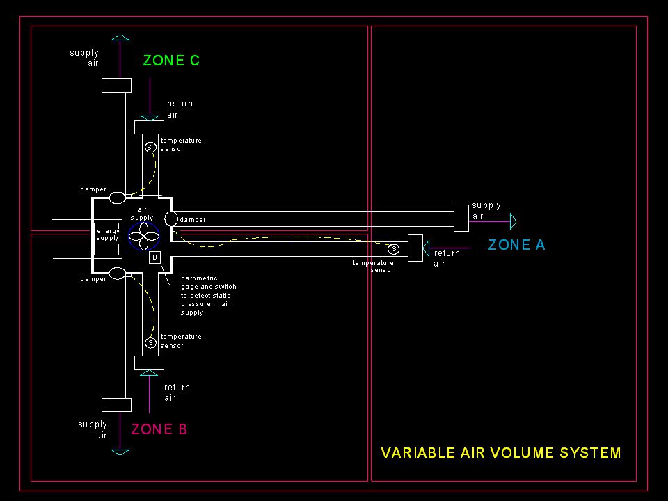
VARIABLE AIR VOLUME SYSTEM
Suitable for medium to large buildings where thermal zones are created within the spaces, primarily due to the movement of the sun. A unit is provided that, at full capacity, can deliver sufficient heated or cooled air to the entire unit system, should the space require 100 percent capacity. Very similar to the type of heating and cooling control in your car, in that one may control the temperature by simply regulating the amount of air delivered. The unit is made with several individual outlets that deliver air, with a thermostat control for each outlet. When air from one of the individual outlets is ducted to a space, a thermal sensor regulates an air damper to vary the volume of air delivered, in concert with the temperature setting of the thermostat. In this system, each outlet from the unit satisfies the demand required by a thermal zone within the building.

6
Variable Air Volume System
Because it is unlikely that all zones within a building require full capacity heating or cooling at the same time, a control must be provided for the motor and fan that produces the air for the system. For a given condition, the fan provides a pressure and volume of air in a chamber from which each outlet emanates. Each outlet damper determines the percentage of air required for a zone, from zero to full capacity. At a given moment, the collective demand from all the outlets served by the chamber determines the total amount of air required for all the outlets, which amounts to a percentage of maximum capacity.

7
Variable Air Volume System
As the requirement for air decreases from maximum capacity, to maintain the proper air pressure in the chamber for the amount required, a barometric control switch within the chamber regulates the variable speed motor that turns the fan, thus producing less or more air as the demand dictates. The unit that controls the variable air volume system can operate on a variety of fuels for heat, such as natural gas, LP gas, oil, or electricity, and cooling generally is provided by a direct expansion refrigeration system.

9
HIGH VELOCITY – DUAL DUCT SYSTEM
For large buildings The system generates cold air at a temperature of 40 – 45 degrees, and warm air at a temperature of 130 – 150 degrees. The generating system is generally remote from the areas to be conditioned. In a high rise building, the mechanical system may be on a floor and deliver air to floors above and below the generating units. Since the system deals with enormous volumes of air, it must be delivered at a very high velocity to accommodate the areas. Air is pushed through ducts at a velocity of from 3,000 to 5,000 feet per minute, to keep ducts as small as practical for the application. Air movement at that speed creates a great deal of noise, so ducts are located in interstitial spaces away from habitable areas. The required amount of air for a given area is collected in a mixing box, which controls the volume of entering air with motorized dampers to allow the proper amount of cool air and warm air to be mixed to the temperature called for by the area thermostat. A thermal sensitive device in the mixing box controls the blades of the motorized dampers.

10
High Velocity Dual Duct System
The required amount of air for a given area is collected in a mixing box, which controls the volume of entering air with motorized dampers to allow the proper amount of cool air and warm air to be mixed to the temperature called for by the area thermostat. A thermal sensitive device in the mixing box controls the blades of the motorized dampers. The air mixed to the desired temperature in the mixing box is then delivered to the given area through ducts that are sized to move the air at a slower rate of speed in habitable areas, eliminating noise caused by fast movement of air. The main advantage to the system is twofold; One, large equipment can be staged to deliver energy in varied amounts to account for the variance of building occupancy. And two, since one thermostat controls one mixing box, any area of thermal zone within a space, large or small, can have controlled temperature, simply by varying the number of mixing boxes.

13
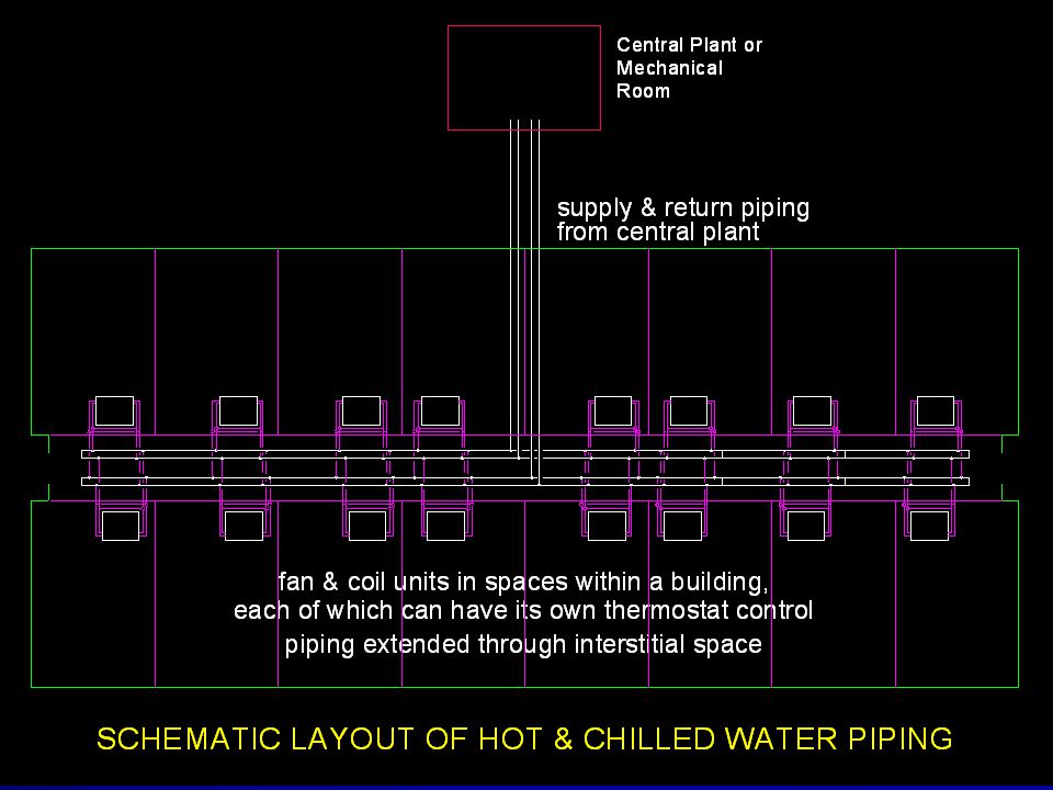
HOT AND CHILLED WATER SYSTEM
A system for medium to very large buildings. A small country hospital, a motel, or nursing home could utilize hot and chilled water. Any facility where a large number of individual controls are needed, not because of thermal zones, but the requirement for private areas to be able to control their own comfort. For cooling, water is chilled to a temperature of 35 to 40 degrees, then pumped through a system of piping to areas where other equipment is used to absorb heat from spaces into the chilled water. The water is then re- circulated back to the chilling unit, and the process continues. For heating, water is heated to a temperature of 180 degrees, then pumped through a system of piping to areas where other equipment is used to add heat to a space. The water is then re-circulated back to the boiler, and the process continues.

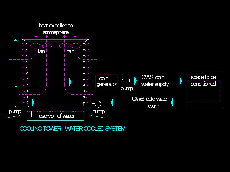
14
Since piping is small compared to ductwork, it can be insulated and extended for large distances without appreciable loss of energy. The mechanical units used to chill and heat water can easily be remote from the subject building, with piping buried underground. The heating cycle is simple, insofar as the process is concerned, precautions made for safety in handling water at a high temperature. The cooling cycle is more complex, since heat is removed from a space with water, then must be deposited to the exterior. Two processes are available for removing the excessive heat from the water; A water cooled system, and an air cooled system. Most all large installations use a water cooled system, since in most cases is more efficient. In the heating and cooling process water is transferred through piping from the central plant to the spaces to be conditioned. At each space, water is circulated through a device called a fan and coil unit, which is controlled by a thermostat.

Similar presentations


![An Introduction To Marine Steam Propulsion Plant [Source: US Navy]](/2/754532/big_thumb.jpg "An Introduction To Marine Steam Propulsion Plant [Source: US Navy]>")

 Systems>")


>")


>")


