Download presentation
Presentation is loading. Please wait.

1
FCQ321 Series training April 2008 FCQ321 Series training April 2008 System Cooking Business Team

2
I.General Specification a)Features and functions b)Specification c)Accessories II.Hardware a)Wiring diagram b)Schematic c)Parts Components III.Disassembly IV.Trouble Shooting a)Trouble shooting flow b)Error message c)Error Trouble shooting V.Reference ContentsAgenda
Features and functions b)Specification c)Accessories II.Hardware a)Wiring diagram b)Schematic c)Parts Components III.Disassembly IV.Trouble Shooting a)Trouble shooting flow b)Error message c)Error Trouble shooting V.Reference ContentsAgenda")
3
General Specification New Appearance Design Family looking Biggest Capacity Self clean and Steam clean Dial control Different pot size Burner

4
Oven Features ★ WHAT’S INCLUDED WITH YOUR RANGE Features & Accessories

5
Control Panel - Oven Functions

6
Control Panel - Surface cooking

7
ModelBasic (FTQ352)New(FCQ321) Color Appearance Stainless Steel(X), Black(B), White(W) APPROXIMATE DIMENSIONS (HxDxW) 47 1/16 in x 25 31/32 in x 29 29/32 in CAPACITY (Oven Capacity)5.7 Cu.ft Cooking TechnologyMulti ConvectionTraditional Element Type5 Ribbon Hidden Bake Oven InteriorYes Oven Type / Cleaning Convection / Self-Cleaning + Steam Cleaning Bake / Self-Cleaning + Steam Cleaning Oven ControlsTouch pad, LED, Blue DisplayKey pad, LED, Blue Display StyleSmoothtop Glass Ceramic CooktopBlack Pattern on Black Glass Convection BakeYesNo Convection RoastYesNo Oven Racks22 6" Heating Element (single)2 Ribbon (1,200 watts) 6"/9“ Dual Heating Element2 Ribbon (2,500 watt)1 Ribbon (2,500 watt) 9" Heating Element (single)No1 Ribbon (2,500 watts) Warming Zone1-6" Ribbon (100 watt) Specification
New(FCQ321) Color Appearance Stainless Steel(X), Black(B), White(W) APPROXIMATE DIMENSIONS (HxDxW) 47 1/16 in x 25 31/32 in x 29 29/32 in CAPACITY (Oven Capacity)5.7 Cu.ft Cooking TechnologyMulti ConvectionTraditional Element Type5 Ribbon Hidden Bake Oven InteriorYes Oven Type / Cleaning Convection / Self-Cleaning + Steam Cleaning Bake / Self-Cleaning + Steam Cleaning Oven ControlsTouch pad, LED, Blue DisplayKey pad, LED, Blue Display StyleSmoothtop Glass Ceramic CooktopBlack Pattern on Black Glass Convection BakeYesNo Convection RoastYesNo Oven Racks22 6 Heating Element (single)2 Ribbon (1,200 watts) 6 /9 Dual Heating Element2 Ribbon (2,500 watt)1 Ribbon (2,500 watt) 9 Heating Element (single)No1 Ribbon (2,500 watts) Warming Zone1-6 Ribbon (100 watt) Specification")
8
ModelBasic (FTQ352)New(FCQ321) FEATURES Auto Self-CleanYes Automatic Self-Clean Oven Door Lock Yes Control Lock CapabilityYes Control LockoutYes Convection ConversionYesNo C° or F° ProgrammableYes Delay Bake Option (Time Bake)Yes Delay Clean OptionYes Electronic Clock & Kitchen Timer Yes Infinite Heat ControlsYes Proof ModeYesNo Keypad ControlsYes Warm ModeYesNo Warming Drawer FeaturesYesNo Heating Element "ON" Indicator Light Yes Hot Surface Indicator Lights1, Cooktop1, Control panel Specification
New(FCQ321) FEATURES Auto Self-CleanYes Automatic Self-Clean Oven Door Lock Yes Control Lock CapabilityYes Control LockoutYes Convection ConversionYesNo C° or F° ProgrammableYes Delay Bake Option (Time Bake)Yes Delay Clean OptionYes Electronic Clock & Kitchen Timer Yes Infinite Heat ControlsYes Proof ModeYesNo Keypad ControlsYes Warm ModeYesNo Warming Drawer FeaturesYesNo Heating Element ON Indicator Light Yes Hot Surface Indicator Lights1, Cooktop1, Control panel Specification")
9
ModelBasic (FTQ352)New(FCQ321) Oven "ON" LightAuto Oven Interior LightYes Control LocationBacksplash Removable Full-Width DrawerYes - Warming DrawerYes – Storage Drawer WEIGHTS & DIMENSIONS Approximate Shipping Weight220 lb (100kg)192 lb (87.2kg) Cabinet Width30 in Net Weight (lbs.) 194 lb (88kg, Included Accessory) 166 lb (75.3kg, Included Accessory) Overall Depth25 31/32" Overall Height47 1/16" Overall Width29 29/32" Oven Interior Dimensions (W x H x D) (in.) 25" x 20 25/32" x 18 15/16" POWER / RATINGS kW Rating at 208V8.99.9 kW Rating at 240V11.913.3 ACCESSORIES Cooktop Cleaning Cream & SpongeIncludedNot included Specification
New(FCQ321) Oven ON LightAuto Oven Interior LightYes Control LocationBacksplash Removable Full-Width DrawerYes - Warming DrawerYes – Storage Drawer WEIGHTS & DIMENSIONS Approximate Shipping Weight220 lb (100kg)192 lb (87.2kg) Cabinet Width30 in Net Weight (lbs.) 194 lb (88kg, Included Accessory) 166 lb (75.3kg, Included Accessory) Overall Depth25 31/32 Overall Height47 1/16 Overall Width29 29/32 Oven Interior Dimensions (W x H x D) (in.) 25 x 20 25/32 x 18 15/16 POWER / RATINGS kW Rating at 208V kW Rating at 240V ACCESSORIES Cooktop Cleaning Cream & SpongeIncludedNot included Specification")
10
Wiring Diagram File

11
Schematic File

12
Schematic

14
1> Turn off the electrical supply going to the range. 2>Pull the range away from the wall so that you can access the rear panel. 3> Remove Cover-Back Main Wire and Cover-Back Guard Wire 4> Remove screws of PCB assembly and separate PCB assembly. ( When you check PCB, check the proper PCB in default mode and check main PCB.) Disassembly COVER-BACK GUARD WIRE, COVER-BACK MAIN WIRE AND PCB-MAIN
 Disassembly COVER-BACK GUARD WIRE, COVER-BACK MAIN WIRE AND PCB-MAIN.")
15
1> Turn off the electrical supply going to the range. 2> Pull the range away from the wall so that you can access the rear panel. 3> Remove Cover-Back Guard Wire 4> Remove Regulator-Energy connectors which be replaced Disassembly REGULATOR-ENERGY

16
4> Pull out the Knob-Dial. 5> Remove 2 screws and replace Regulator-Energy. Disassembly REGULATOR-ENERGY

17
CERAMIC GLASS COOKTOP REMOVAL 1> Unplug the cord or disconnect power 2> Open oven door and remove the 3 screws located at the front of the cook-top, then close the door. 3 Screws 3> Slightly lift up and pull up the cook-top and then unplug the 2 connectors wire at the back by squeezing side tabs and unscrew ground wire. Disassembly HEATER-RADIANT

18
4> Protect the cooktop surface and turn the assembly over. 5> To remove the surface elements a) Remove the wires from the element and limiter terminals. b) Remove the element bracket screw (shown below) for the element you are servicing. c) Carefully lift the bottom of the bracket just far enough to remove the element. d) Use sharp tool to remove the heating element REASSEMBLY NOTE: When you reinstall the element make sure that the wires are inserted into the correct tap then reinstall the bracket screw to secure it to the cooktop. Disassembly HEATER-RADIANT
 Remove the wires from the element and limiter terminals. b) Remove the element bracket screw (shown below) for the element you are servicing. c) Carefully lift the bottom of the bracket just far enough to remove the element. d) Use sharp tool to remove the heating element REASSEMBLY NOTE: When you reinstall the element make sure that the wires are inserted into the correct tap then reinstall the bracket screw to secure it to the cooktop. Disassembly HEATER-RADIANT.")
19
1> Turn off the electrical supply going to the range. 2> Open the oven door. 3> Raise the cooktop 4> Remove the cooktop To remove the door latch: a) Remove two screws from the front of cavity. b) Remove a screw from Cover-Back Guard and remove latch-door. Disassembly LATCH-DOOR AND SWICH-DOOR PLUNGER
 Remove two screws from the front of cavity. b) Remove a screw from Cover-Back Guard and remove latch-door. Disassembly LATCH-DOOR AND SWICH-DOOR PLUNGER.")
20
Disassembly LATCH-DOOR AND SWICH-DOOR PLUNGER

21
Disassembly HEATER-BROIL

22
HEATER-BAKE Disassembly

23
To replace bulb and bulb cover: 1> Disconnect power. 2> Remove oven door. 3> Turn the glass bulb cover in the back of the oven counterclockwise to remove. 4> Turn bulb counterclockwise to remove from socket. 5> Replace bulb and bulb cover by turning clockwise. To replace socket assembly: 6> Disconnect the wires from the socket terminals. 7> Use a screwdriver and bend the clips on the socket away from the edges of the liner hole(there are 6 clips on th e socket), and pull the socket out of the liner. Push the socket out from the back of the unit. CAUTION Be careful not to scratch or chip the oven liner paint when you remove the oven light socket in the next step. Lamp Disassembly
, and pull the socket out of the liner. Push the socket out from the back of the unit. CAUTION Be careful not to scratch or chip the oven liner paint when you remove the oven light socket in the next step. Lamp Disassembly.")
24
TEMPERATURE SENSOR Disassembly

25
STORAGE DRAWER Disassembly

26
To remove the door: 1> Fully open the door. 2> Pull the hinge locks downward (Fig.1) 3> Firmly grasp both sides of the door at the top. 4> Close door to the door removal position, which is approximately 5 degrees. (refer to the Fig.2) Lift door up and out until the hinge arm is clear. OVEN DOOR Disassembly
 3> Firmly grasp both sides of the door at the top. 4> Close door to the door removal position, which is approximately 5 degrees. (refer to the Fig.2) Lift door up and out until the hinge arm is clear. OVEN DOOR Disassembly.")
27
To replace the door: 1. Firmly grasp both sides of the door at the top position. 2. With the door at the same angle as the removal position, seat the indentation of the hinge arm into the bottom edge of the hinge slot. The notch in the hinge arm must be fully seated into the bottom of the slot. 3. Fully open the door. If the door will not fully open, it means that the indentation is not seated correctly in the bottom edge of the slot. Push the hinge locks up to the locked position. 4. Close the oven door. OVEN DOOR Disassembly

28
1> Remove the oven door from the range. 2> Place the oven door on a padded work surface with the front glass facing down. 3> Remove 3 bottom screws from the door. 4> Remove 2 Handle-screws from the door. 5> Lift the door rear assembly off the front assembly and set it aside. HANDLE-DOOR AND GLASS-INNER Disassembly

29
HANDLE-DOOR AND GLASS-INNER Disassembly

30
to HANDLE-DOOR AND GLASS-INNER Disassembly

31
HANDLE-DOOR AND GLASS-INNER Disassembly

32
1> Open the oven door to its fully down position. 2> Pull the ends of the gasket out of the liner holes. 3> Pull the oven door gasket clips out of the holes until all of the clips are removed. REASSEMBLY NOTE: When you install the new gasket, make sure that all of the clips are seated in their liner holes, and that the ends of the gasket are pushed fully into their holes. Use the pointed end of a pencil to push the gasket ends into the holes. GASKET-DOOR Disassembly

33
1> Turn off the electrical supply. 2> Remove the oven door from the range 3> Pull the range away from the wall so you can access the back of the unit. 4> Remove the 12 screws from the rear of Panel-Side and remove Cooktop. 5> Remove the (each) 3screws from the top the Panel-Side. 6> Pull the back of the side panel out from the range approximately 10˚(degree) 7> Push forward and remove Panel-Side. PANEL-SIDE Disassembly
 3screws from the top the Panel-Side. 6> Pull the back of the side panel out from the range approximately 10˚(degree) 7> Push forward and remove Panel-Side. PANEL-SIDE Disassembly.")
34
Trouble Shooting Parts Checking Method

35
Trouble Shooting

36
Parts Checking Method Trouble Shooting

37
Parts Checking Method Trouble Shooting

38
Parts Checking Method Trouble Shooting

39
Parts Checking Method Trouble Shooting

42
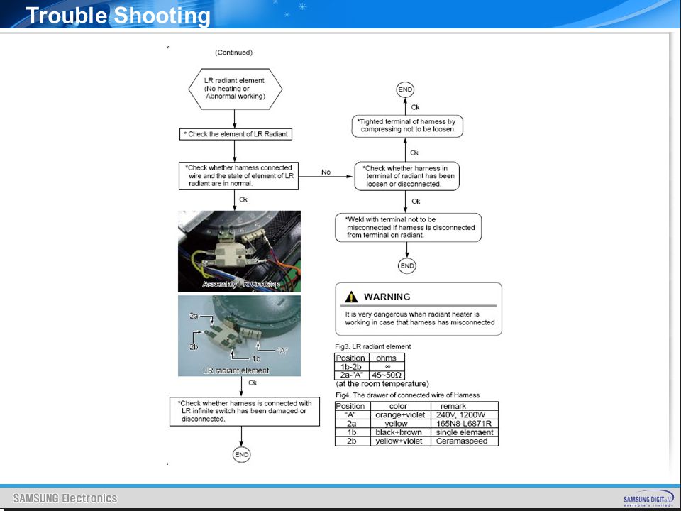
Cook-top No heating or Abnormal working Trouble Shooting

57
Reference Checkpoints before service request

58
Reference

60
Thanks SAMSUNG

Similar presentations


 2.Wired barcode scanner holder (optional) 3.Mouse holder and tray 4. Removable rear technology panel 5. Power cord.>")


