Download presentation
Presentation is loading. Please wait.

2
Nablus tower is a multi storey building of 21 stories. These stories produce heavy loads above the soil. This building is relatively heavy if we compared it with the ordinary buildings in the city which almost do not exceed 12 or 13 stories each. So the design of the footing will be more critical and needs special care and attention.

3
This tower is the first tower in Nablus city and in the north of West Bank. It lies in Rafeedia main street to the west of Nablus The height of the tower is 80 meters. The area of the first 15 stories is 990m 2 And the area for the last 6 stories is 530 m 2

4
GOOGLE EARTH

6
1- Select the most appropriate types of foundations for the project. 2- Design the selected footings. 3- Calculate the settlement. 4- Estimate costs of the foundations designed.

7
Shear Parameters Specific gravity Atterberg limits % finer sieve #200 Moisture Content (%) Sample depth (m) BH.No. Ф(o)Ф(o) C (KN/m 2 ) PILL 20182.7316.538.442.89.50-6 1 18282.7322.750.248.820.56-20 21172.7315.937.544.210.20-6 2 2.7319.941.25118.56-7 2.7322.17-20 24152.7216.937.545.59.80-7 3 2.7317.57-20 2118100-3 4 18.13-6 20.659.449.5206-20 201745.99.70-6 5 2.732044.352.122.86-14 20.614-20 21182.7316.437.942.911.20-6 6 2.7319.84144.817.16-7 19.87-20
Ф(o) C (KN/m 2 ) PILL")
8
The weights of the whole structure were calculated by using the Tributary area method,then we have found the loads on each column. Total load of the whole structure = Loads from first 15 stories + last 6 = 28531 + 6100 = 34631 ton.

10
Col.Service Load (tons)Ultimate Loads(tons) A1555702 A211151419 A912501591 A10577730 B1+C19051158 B219152470 B915822040 B10+C10754965 D1597763 D212611625 D3+D517592271 D6+D817072203 D912931667 D10636814 E1612781 E210371263 E3+E512361592 E6+E812001546 E99421213 E10596735
Ultimate Loads(tons) A A A A B1+C B B B10+C D D D3+D D6+D D D E E E3+E E6+E E E")
11
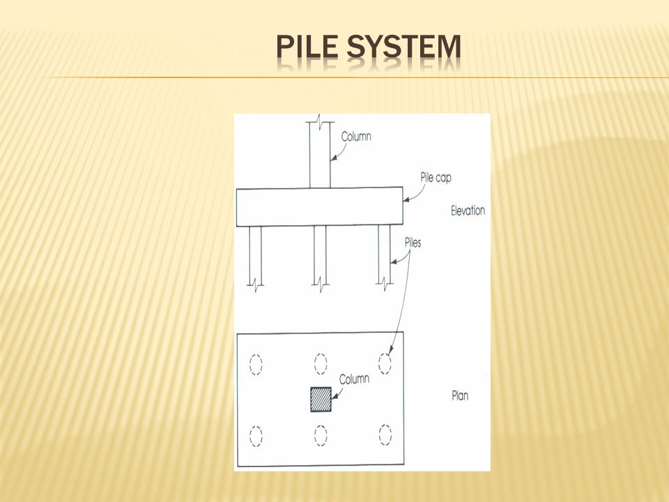
After calculating the loads on each column, we have decided to use PILE FOUNDATION SYSTEM due to the heavy loads existed, the soil bearing capacity is medium, so this had led us also to use this system. In this design we made many iterations to achieve the perfect design. Using one pile or two piles in one cap is not preferred because of the instability in this case, so we have tried to use 5 piles in one cap or more depending on the loads on each column.

12
Number of piles in the one cap was restricted by the geometry of the whole system. The over lapping between piles was the main reason in this case. The minimum distance between two piles was 2.5 the diameter of the pile So the loads and the minimum distance between two piles were the two main factors in the design. The diameter of the pile is 100 cm and it is the same in every pile, also we tried in this case to achieve practical design.

13
The footing under the shear walls area was designed in a different way. Due to the heavy loads and the limited area, piles are not chosen. We have designed it as MAT FOUNDATION. The area of mat foundation is approximately 180 m 2

14
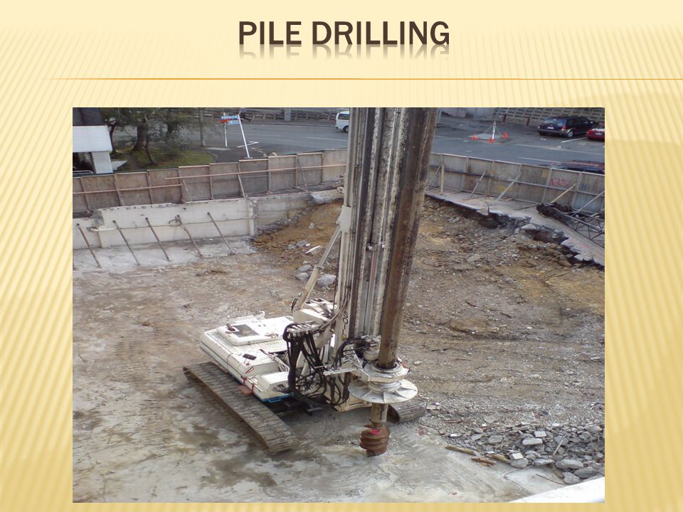
The design of the piles was done by ALL PILE program.

17
Col. Service Load (tons) Ultimate Loads(tons) No. of PilesLength(m) Diameter (cm) A1555702516100 A211151419526100 A912501591626100 A10577730517100 B1+C19051158523100 B219152470926100 B915822040825100 B10+C10754965520100 D1597763517100 D212611625626100 D3+D517592271727100 D6+D817072203727100 D912931667626100 D10636814518100 E1612781517100 E210371263526100 E3+E512361592626100 E6+E812001546625100 E99421213524100 E10596735517100
 Diameter (cm) A A A A B1+C B B B10+C D D D3+D D6+D D D E E E3+E E6+E E E")
18
Col. Settl. in one pile (mm) Bg(m) group pile settlement(mm) RsN 0.5 A11.55.63.52.332.24 A235.67.12.372.24 A933.75.81.932.45 A101.65.63.82.382.24 B1+C12.53.74.81.922.24 B236.27.52.53 B92.86.372.52.83 B10+C1025.64.72.352.24 D11.65.63.82.382.24 D235.67.12.372.45 D3+D53.26.282.52.65 D6+D83.26.282.52.65 D933.75.81.932.45 D101.85.64.32.392.24 E11.65.63.82.382.24 E235.67.12.372.24 E3+E536.27.52.52.45 E6+E82.96.27.22.482.45 E92.75.66.42.372.24 E101.75.642.352.24
 Bg(m) group pile settlement(mm) RsN 0.5 A A A A B1+C B B B10+C D D D3+D D6+D D D E E E3+E E6+E E E")
19
As = ρ X area = 0.005 (π/4)(1000) 2 = 3927 mm 2 Use 15 Ф 18 It is recommended to use spiral stirrups 1Ф8 mm / 10 cm.
(1000) 2 = 3927 mm 2 Use 15 Ф 18 It is recommended to use spiral stirrups 1Ф8 mm / 10 cm.")
20
Col.Depth(m)Col.Depth(m) A10.50D3+D52.0 A20.85D6+D81.50 A91.50D91.60 A100.50D100.55 B1+C10.50E10.45 B21.50E20.75 B91.85E3+E50.65 B10+C101.55E6+E80.60 D10.50E90.80 D20.90E100.50
Col.Depth(m) A10.50D3+D52.0 A20.85D6+D81.50 A91.50D91.60 A100.50D B1+C10.50E10.45 B21.50E20.75 B91.85E3+E50.65 B10+C101.55E6+E80.60 D10.50E90.80 D20.90E100.50")
22
Col.Depth(h)M11(KN.M)As(cal)As minAs usedreinf. A10.5449577216505772 7Ф32 A20.85941439028054390 6Ф32 A91.5128627644950 6Ф32 A100.5496657516506575 8Ф32 B1+C10.53213849165038498Ф25 B21.584518054950 6Ф32 B91.85196833016105 8Ф32 B10+C101.554779755115 7Ф32 D10.5394490516504905 6Ф32 D20.91042447129704471 6Ф32 D3+D5275511456600 8Ф32 D6+D81.5918.519644950 6Ф32 D91.61102155280 7Ф32 D100.55478480118154801 6Ф32 E10.50291344016503440 7Ф25 E20.75742419124754191 9Ф25 E3+E50.65615444121454441 6Ф32 E6+E80.6560471619804716 6Ф32 E90.87623869264038698Ф25 E100.54746191165061918Ф32

23
Col.Depth(h)M22(KN.M)As(cal)As minAs usedreinf. A10.511412531650 4Ф25 A20.851888372805 6Ф25 A91.53637714950 6Ф32 A100.6143 11061650 4Ф25 B1+C10.5541741216507412 9Ф32 B21.54088674950 6Ф32 B91.851622686105 8Ф32 B10+C101.5588018075115 7Ф32 D10.512413681650 4Ф25 D20.91907792970 6Ф25 D3+D525057656600 8Ф32 D6+D81.554611624950 6Ф32 D91.63677215280 7Ф32 D100.551059471815 4Ф25 E10.5011512461650 4Ф25 E20.7521611622475 5Ф25 E3+E50.65741547021455470 7Ф32 E6+E80.6608518019805180 7Ф32 E90.820610032640 6Ф25 E100.514115651650 4Ф25

24
M11M22

25
Moments are not uniformly distributed, so there were no column strips nor middle strip. We divided the mat into several parts.Then we read the maximum moment in each part, and the reinforcement calculated was depending on this reading.

26
X - direction

27
Y – direction

28
The dimensions were suggested to be 40*70 cm as below As = ρ * b * d = (0.0033)(400)(640) = 844.8 mm 2 use 5Ø16 bottom steel. use 5Ø16 top steel. cover = 6cm. (Av/s) = Min ((3.5 bw/fy), (0.2 bw /fy)) (Av/s) = 0.033. use 1Ø10/30 cm
 = Min ((3.5 bw/fy), (0.2 bw /fy)) (Av/s) = use 1Ø10/30 cm.")
29
In order to estimate the total cost we have to calculate the concrete cost, the steel costs, and the cost of drilling the piles. Concrete costs based on size calculations. Steel costs based on weight calculations. Drilling costs based on lengths costs (the diameter is constant)
.")
30
The total cost of concrete = 3152*320 = 1008640 Total cost of steel= 112*3300 = 369600 NIS Cost of the drilling = 2690*50 = 134500 NIS Total cost of the concrete, steel, and drilling = 1008650+369600+134500 = 1,512,750 NIS. ≈ 1.513.000 NIS

31
Finished Thank you for listening

Similar presentations


 Determine the own weight of building 2) Design of mat foundation 3) Design of pile foundation.>")


: A rectangular beam has the dimensions shown in Figure 4.12.a and is loaded with a 40 ton concentrated.>")


