Download presentation
Presentation is loading. Please wait.

1
Detailed Design Review December 5 th, 2013 P14311: PCB Isolation Router System

2
Agenda I. Project Background Review II. Detailed Design Reviews III. Bill of Materials and Budget Review IV. Risk Management V. Preliminary MSD II Plan

3
Agenda I. Project Background Review a) Scope of Project b) Engineering Requirements Update
 Scope of Project b) Engineering Requirements Update")
4
Problem Statement RIT students need rapid prototyping for creation of unique circuit boards Requires multiple revisions to perfect each circuit board Currently each iteration must be created off campus Long lead times Expensive Limits circuit refinement Students not involved in process

5
Engineering Requirements Update Requirement #ImportanceSourceEngr. RequirementUnit of MeasureMarginal ValueIdeal Value 19C1Physical Footprintft^3408 29CR9, C16Eliminate potential for injuriesBinaryPass 39C10Noise GenerationdBA<100<75 49CR11Minimum Width Between Traces Supportedinches0.0200.016 53C13Manufacturing Cost$28002000 69CR14, CR15Unit Reliability (mean time between failures)hours15003000 79CR15Mean to time between maintenancehours50100 81CR17Compatible with English and Metric units of measureBinaryPass 99CR18Minimum Tolerance to locating positions on boardinches0.0050.001 103CR19Detection of Errors%98100 113CR2, CR20Design EvaluationBinaryPass 123C21Tool Replacement Timeminutes2<= 1 133C21Feed Ratein/minute10100 143CR22Time for initial machine set-upminutes6030 153CR22Weight of Machinelbs600300 169CR3, CR5Depth of Material to be removedinch0.001370.125 173CR4Maximum Compatible Board Sizeinch x inch5 x 58.5 to 11 183CR4Minimum Compatible Board Sizeinch x inch2 x 21 x 1 199CR6Required Voltage for OperationVolts120 203C7Maximum Tool Bit Sizeinches0.1250.25 213C7Minimum Tool Bit Sizeinches0.0160.006 229C8Compatible with External PC for system controlBinaryPass 239CR9, C16, CR12Minimize Operator Traininghours1.5.5 hours 249C21Router Speedrpm1500030000 259C10Debris Removal (Copper and Substrate)mg11.71.7 269CR11TIRinches<.0006<0.0004 279CR3Vacuum Table Forcelbs force3040 289CR2Max Power Consumption for entire systemwatts19201800
hours CR15Mean to time between maintenancehours CR17Compatible with English and Metric units of measureBinaryPass 99CR18Minimum Tolerance to locating positions on boardinches CR19Detection of Errors% CR2, CR20Design EvaluationBinaryPass 123C21Tool Replacement Timeminutes2<= 1 133C21Feed Ratein/minute CR22Time for initial machine set-upminutes CR22Weight of Machinelbs CR3, CR5Depth of Material to be removedinch CR4Maximum Compatible Board Sizeinch x inch5 x 58.5 to CR4Minimum Compatible Board Sizeinch x inch2 x 21 x 1 199CR6Required Voltage for OperationVolts C7Maximum Tool Bit Sizeinches C7Minimum Tool Bit Sizeinches C8Compatible with External PC for system controlBinaryPass 239CR9, C16, CR12Minimize Operator Traininghours1.5.5 hours 249C21Router Speedrpm C10Debris Removal (Copper and Substrate)mg CR11TIRinches<.0006< CR3Vacuum Table Forcelbs force CR2Max Power Consumption for entire systemwatts")
6
Agenda II. Detailed Design Reviews a) Family Tree Diagram Review b) Mobile Enclosure Review c) Milling Machine Assembly Review d) Base Cabinet Assembly Review e) Electronics Control Box Review f) Miscellaneous Electronics g) Supply/Interconnect System Review h) User Interface Assembly Review
 Family Tree Diagram Review b) Mobile Enclosure Review c) Milling Machine Assembly Review d) Base Cabinet Assembly Review e) Electronics Control Box Review f) Miscellaneous Electronics g) Supply/Interconnect System Review h) User Interface Assembly Review.")
7
Family Tree Diagram

8
Final Design

9
Mobile Enclosure Design Review

10
Mobile Enclosure General Description Mobile Computer Workstation Pull-out tray The bottom compartment adjusts 2 3/8” increments Unit has four swivel casters (two with brake) with 4” dia. hard-rubber wheels Louvered cutouts for ventilation and wire- management grommets Mechanical Dimensions Top Compartment, Inside Size Width – 25 7/8” Depth – 23 1/8” Height – 23 3/8” Bottom Compartment, Inside Size Width – 25 7/8” Depth – 22 3/8” Height – 23 7/8” Color Light Gray Material 20- to 18-ga. Steel

11
Milling Machine Assembly Review

12
Zen Tool Works CNC DIY Kit Electrical/Mechanical Characteristics: Travel capacity: 7” (X) x 7” (Y) x 2” (Z) High density PVC frame Steel guide rods with precision linear bearings Stainless steel M8 x 1.25 lead screws with ball bearing supports Brass anti-backlash lead screw nuts Shinano dual shaft NEMA 17 stepper motors
 x 7 (Y) x 2 (Z) High density PVC frame Steel guide rods with precision linear bearings Stainless steel M8 x 1.25 lead screws with ball bearing supports Brass anti-backlash lead screw nuts Shinano dual shaft NEMA 17 stepper motors")
13
Router Assembly

14
Variable Speed Router Kit Basic Description: Variable Speed Router Kit Materials: Plastic body with cast aluminum base Size Router dimensions: 3.75” diameter, 3.3 lb weight Collet Size Variable speed: 16,000-35,000 rpm Motor Rating: 1 hp Safety Listings: UL and CSA Packaging: Plastic carrying case with room for associated tools Electrical requirements: 120V AC, 5.6A

15
Collet Kit List of Components 1/8 in. Precision Grade (PG) Colt collet (BOPG-COLT-1250) Collet nut (BOPG-1618-NUT) Spanner wrench (BOPG-1618- TLN) Calibration blank (CB0000- 1250-150MIT) 118 ml of ColletCare (MI00- 0096-118) Solvent, light lubricant and corrosion inhibitor mixture that cleans, conditions and protects *All components can be purchased separately through the purchase source
 Colt collet (BOPG-COLT-1250) Collet nut (BOPG-1618-NUT) Spanner wrench (BOPG TLN) Calibration blank (CB MIT) 118 ml of ColletCare (MI ) Solvent, light lubricant and corrosion inhibitor mixture that cleans, conditions and protects *All components can be purchased separately through the purchase source.")
16
Router Support Structure

18
Air Pressure Solenoid SMC 3 Port Solenoid Valve Operating Pressure Range: 0 to 0.7 Mpa Response Time ≤ 5 ms Voltage: 24, 12, 6, 5, 3 volts Port Size: M5 x 0.8 Used to control air flow through debris management system Nozzle will only be blowing when router is on Power Supply for the solenoid and router will be the same

19
Vacuum Clamp Assembly

20
Made from aluminum 13 x 13 grid pattern Holes are ½” spacing Support brackets inside of table to ensure a flat surface Use RTV sealer during assembly to prevent leaks

21
Registration System Originally Plan: User defined pin locations Problems with vacuum hole interference Revised system includes pre-set pin hole locations

22
Base Cabinet Assembly Review

23
Vacuum System Shop-Vac 5895400 model Fits nicely into our system design Provides more CFM and Power than Vacuum used for testing Low cost(~ $70) Purchased: Shop-Vac Test Vacuum: Rigid CFM170110 HP4.55 Size(gallons)44 Air Watts290167
 Purchased: Shop-Vac Test Vacuum: Rigid CFM HP4.55 Size(gallons)44 Air Watts290167")
24
Vacuum System Calculations Shop- Vac 5895400Rigid(From Testing)
")
25
Electronics Control Box Review

27
Electronics Box 15” x 15” x 4” Maximum Aluminum Cooling Fans to direct heat flow up and out of box Mounted on outside of enclosure for easy access for maintenance

28
Controller PCBA

29
Features: Can be externally or USB powered Works with Mach3 software via plug-in Up to 100kHz operation 49 digital inputs and 36 digital outputs 2 analog inputs and 2 analog outputs On-board interpolations with buffers for robust and fast operation Jog, E-stop, limit switch, and reference inputs Router speed control

30
26 & 16 Pin Header Pin Out

31
Motor Drivers PCBA

32
Basic Information: 0.5 to 2.5 amps phase current Current selectable via jumper If the PCBA is in an enclosed environment or the operational current is greater than or equal to 1.5A, incorporate an additional cooling method (Fan). +10 VDC to +27 VDC power supply Capable of 1, 2, 4, and 16 micro-steps per step 3.3V and 5V logic compatible inputs 500 KHz max step frequency 0 °C To 70 °C operating temperature LED power and enable indicators Board Dimensions: Metric: (50 x 52) millimeters Imperial: (2 x 2.05) inches Board height: Metric: 15 millimeters Imperial: 0.6 inches
 millimeters Imperial: (2 x 2.05) inches Board height: Metric: 15 millimeters Imperial: 0.6 inches.")
33
10 Pin Header Pin Out

34
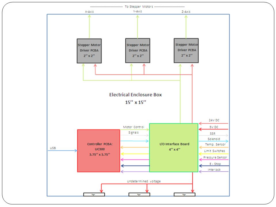
I/O Interface Board Reasons for Having an I/0 Interface Board Needed isolation for motor control signals Gain stage to magnify temperature sensor signal Will make connections between the Controller PCBA and I/Os much cleaner Ability to host a variety of connector types including ribbon cable, flexible film connectors, and screw terminals Sizing: Chose 4’’ x 4’’ footprint to ensure at least 2’’ spacing between each PCBA and the walls of the 15’’ x 15’’ enclosure.

35
I/O Board Schematic Page 1: Signals From Controller Board Port 3

36
I/O Board Schematic Page 2: Router/Vacuum Shutoff and Stepper Power

37
I/O Board Schematic Page 3: Signals to Controller Board Port 4

38
I/O Board Schematic Page 4: Analog Signals

39
Miscellaneous Electronics

40
Low Voltage Power Supply Electrical Specifications: Output Specifications: Isolated output and ground for Channel 1 and Channel 2 Channel 1 Ratings: 24V, 9.4A (Peak 16.7A) Channel 2 Ratings: 5V, 5A Total Rated power (for both channels): 250.6W Provides power to stepper motors (24V) and isolation board (5V)
 Channel 2 Ratings: 5V, 5A Total Rated power (for both channels): 250.6W Provides power to stepper motors (24V) and isolation board (5V)")
41
Interlock Switch When Interlock is broken Sends a pause signal to controller board to pause the program Stops power to: Router Motors Switch has not yet been selected

42
Emergency Stop Switch Stops power to entire system Contact Rating 8A @ 125 VAC 6A @ 24VDC E Switch L16 Series Illuminated, Pilot Indicator

43
Solid State Relays Specifications: Dual channel Each output channel rated for 25A at 280VAC Control voltage 4-15VDC 4kVAC optical isolation between input and output Zero-crossing voltage turn on Latching input terminal 80°C max operating temperature 8.33millisecond turn-on time

44
Supply/Interconnect System Review

45
120 VAC Power Cord Plan to make our own custom power cord using. Plug will be bought from manufacturer Cabling will be type SJT Length will be cut to size once we consult customer for preference Why SJT? Higher current rating than SVT Higher temperature rating than SVT Larger wire gauge will fit Example NEMA 5-15 polarized plug rated for 15A at 120VAC shown

46
Signal Flow Table Example (UC300)
")
47
Signal Flow Table Example (I/0 Board)
")
48
Power Distribution Vacuum Receptacle Box Router Receptacle Box 120VAC Wall Outlet I/O Interface Board Main controller board Motor Driver Board X Motor Driver Board Y Motor Driver Board Z PC USB 5VDC Electronics Box PC Receptacle Box 674W MAX 1080W MAX LVPS E-STOP Interlock Switch SSR Box 120VAC 24VDC COM NO NC Safety Relay 24VDC 60-250W 24VDC E-STOP_STATUS INTERLOCK_STATUS

49
Pressurized Air Line Interior connection to mill head Flexible air line to accommodate x and z direction movement Adjustable nozzle position to maximize debris collection of vacuum Exterior connection to compressed air supply Standard ¼” NPT quick release fittings Flexible air line to accommodate placement of entire machine Supplied Pressure in lab is 80 psi Regulator to adjust pressure to amount needed

50
Vacuum Table and Debris Management Ducting Schedule 40 PVC piping will be used for most vacuum ducting components Smooth inner surface to minimize losses Rigidity will prevent collapse “Off-the-shelf” components Movement Vacuum table moves in y-direction only Can use a rigid or flexible connection Mill Head moves in x and z directions Will require some flexible ducting

51
System Heat Analysis The maximum temperature of the top enclosure would be 37.7 °C (About 100° F). We do not need to be concerned with this because our piping/ducting is rated up ~130°F.

52
User Interface Assembly Review

53
User Interface Assembly For now, User Interface Assembly will be stationed on an external table next to enclosure Mounting Interface to the enclosure may be developed in future if time and resources are available

54
Mach3 Interface Open Source software solution Fully customizable GUI Allows direct import of DXF, BMP, JPG, and HPGL files through LazyCam Router Speed Control Video Display of machine Wide variety of wizards available Supports large files (10,000,000 lines) Widely used with online support
 Widely used with online support")
55
Agenda III. Bill of Materials and Budget Review IV. Risk Management Review V. Preliminary MSD II Plan

56
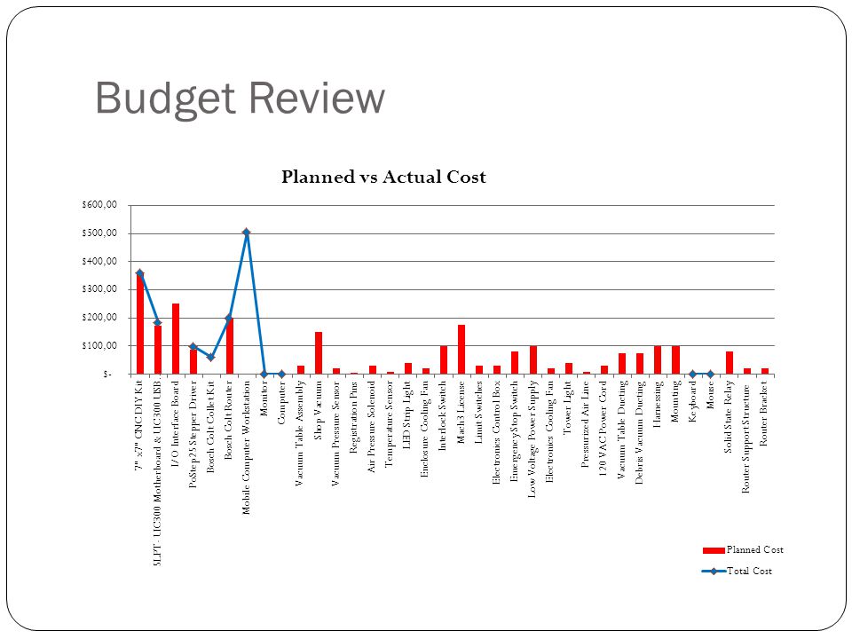
Bill of Materials Item #Part NumberDescription/NameQuantityManufacturerManufacturer Part NumberUnit CostExtended CostShipping CostTotal Cost 1V000017" x7" CNC DIY Kit1Zen Tool WorksZEN0707$359.99 2V00002 5LPT- UC300 Motherboard & UC300 USB Motion Controller1CNC4PCna$174.00 $9.98$183.98 3V00003I/O Interface Board1 4V00004PoStep25 Stepper Driver3CNC4PCna$29.00$87.00 $9.98$96.98 5V00005Bosch Colt Collet Kit1Think and Tinker Ltd.BOPG-COLT-8KIT$51.26$56.95$13.38 $ 60.69 6V00006Bosch Colt Router2Bosch $99.00$198.00$0.00 $ 198.00 7V00007Mobile Computer Workstation1McMaster-Carr49175T4$433.85 $70.00 $ 503.85 8V00008Monitor1N/A $ - 9V00009Computer1N/A $ - 10V00010Vacuum Table Assembly1 11V00011Shop Vacuum1 12V00012Vacuum Pressure Sensor1 13V00013Registration Pins4 14V00014Air Pressure Solenoid1 15V00015Temperature Sensor1 16V00016LED Strip Light1 17V00017Enclosure Cooling Fan1 18V00018Interlock Switch1 19V00019Mach3 License1 20V00020Limit Switches 21V00021Electronics Control Box 1 22V00022Emergency Stop Switch 1 23V00023Low Voltage Power Supply 1 24V00024Electronics Cooling Fan 3 25V00025Tower Light 1 26V00026Pressurized Air Line 1 27V00027120 VAC Power Cord 1 28V00028Vacuum Table Ducting 1 29V00029Debris Vacuum Ducting 30V00030Harnessing 31V00031Mounting 32V00032Keyboard 1 $ - 33V00033Mouse 1 $ - 34V00034 Solid State Relay1 35V00035 Router Support Structure1 36V00036 Router Bracket1

57
Budget Review

59
Risk Management Review IDRisk ItemEffectCauseLikelihoodSeverityImportance Action to Minimize Risk Contingency PlanOwner 1 Cannot mill to specified tolerance Unhappy customer, device has limited usability Poor design, testing, and analysis 236 Purchase of parts capable of meeting specs. Design and testing of control system Redesign of system and purchase of new parts Marley 2 Individual Tasks are not completed Delayed deliverables, low quality of work Team members do not have time resources to complete 236 Create clear action items list after every meeting with dealines. Team members should also look for support on activities where they have limited time resources to complete. Divide and Conquer the tasks still needing completion Sarah 3 Product does not meet RIT's safety requiremen ts Machine cannot be used on RIT Campus Not following RIT's safety regulations throughout the design process 236 Review designs and decisions with RIT EHS Meet with RIT EHS to determine what can be done post production to bring the device up to code Sarah 4 Machine cannot manage debris when running Will cause lab to be messy and potential harm to user Failure develop adequate concept for removing debris 236 Know and understand existing procedures for debris removal Re-design a device or system for safe debris removal Matt 5 Bit drills too deep Damages the device if it drills past the artificial layer Inaccurate motor control 236 Correct programing and testing of motor control Redesign of a thicker artificial layer Zoe

60
IDRisk ItemEffectCauseLikelihoodSeverityImportance Action to Minimize Risk Contingency PlanOwner 6 Mismanage d Budget Lacking Reasources, team must alter design to fit new constaints Poor Communication, and tracking of purchases 224 Appoint 1 team member as buyer. Create a budget spreadsheet to keep track of purchases. Design system around the resources available Sarah 7 Power Supply Power Supply does not provide enough power to run the electronic components Machine is built to require more power than available in a regular outlet. 224 Design to power tolerance available Joe 8 Vacuum Table doesn't hold down part Part could fling out; Imprecise milling Inaccurate calculation of vacuum holding force 224 Double check calculations and provide adequate testing, Use registration pins A new system for PCB hold-down will have to be developed Matt 9 Bug in Software Incorrect traces Poor Design and Testing 224Bug testingRe-write softwareJoe 10 Air leak during operation Inefficient system, improper vacuum hold- down Improper sealing or material failure 224 Take precaution to seal joints and choose adequate materials Redesign of vacuum, or choice of hold- down system Matt 11 Lead screw wear Inaccurate milling of the PCB Screw cannot handle weight force or torque 224Proper force analysis Have extra parts on hand Marley 12 Motor has chatter Inaccurate milling of the PCB Improper control or damping 224Tune the motor Return and purchase new motor Zoe 13 Problems locating the PCB Accuracy of milling affected Hold-down mechanism interferes with locating 224Test for interference Re-design of hold- down mechanism RJ

61
IDRisk ItemEffectCauseLikelihoodSeverityImportance Action to Minimize Risk Contingency PlanOwner 14 Oversized System Does not fit in the space alloted in the lab Poor Design133 Create detail models to show overall size prior to building costly prototype to verify size is within limits Redesign to fit size spec MEs 15 Team cannot complete design Delayed deliverables, low quality of work Poor Time Management in 3 week cycles 133 Use Project Schedule every day to understand key milestone dates and see if project is falling behind Multiple All-nightersSarah 16 Changes in Customer needs Change in scope of the project Misunderstood needs or customer opinion changed 133 Confirm at every review and large decision gates that project scope is still the same in eyes of customer Divide and assign new design work in manageable sections Marley 17 Stepper motor not located properly Destruction of PCB design and possibly the device itself Coding Issue133Sensors at edge of railsFail-safe within codingJoe 18 Interlock is forced open Severe safety risk to operator Improper training, or mechanical failure 133 Implement additional fail safes Sarah 19 Motors Burn out/ Break Device is non- operational Power surge issue; inherant part failure 133 Have extra motors on hand Evaluate product reliability Zoe 20 Time delay in controls Time delay stacks affect system control Less than ideal control and system response 313 Optimize program delays Allow for delays in process Kevin 21 Difficulty interfacing between software Lacking a system response Unfamiliarity with the software 313 Use resources to become familiar with the software Choose different software Joe 22 Unsafe Failure Mode Harm to operator Safety precautions not integrated into design 133 Familiarize and implement safety precautions into design, then conduct extensive tesitng Allow for no operational hazards in design Sarah 23 Structure fails to hold rig securely Damage to the device Structural design flaw 133 Use proper materials, and design structure with adequate factor of safety Implement back-up system for structural failure Marley

62
IDRisk ItemEffectCauseLikelihoodSeverityImportance Action to Minimize Risk Contingency PlanOwner 24 Long Lead Time for purchased parts Cannot complete milestones on given time scale Poor planning and communication, and trouble thinking ahead 122 Develop Make vs Buy plan during Sub systems design and start pricing buy items to identify long lead times Find alternative part for design Sarah 25 PCB geometry makes it unable to be secured PCB cannot be milled without effective hold- down PCB hold-down design limits acceptable geometry 122 Design hold-down to account for the majority of PCB geometries Move in a new direction with hold- down design that doesn’t account for geometry Matt 26 Documentat ion is Lacking Future Senior Design groups cannot build off of our system, Unhappy customer, Unsafe to operate Not keeping up with documentation throughout the process 122 Documentation Manager creates thourough notes for every event, Project Manager creates project book to be handed off at the end of the term. Leave future project design groups with less than ideal background information Zoe 27 Lead screw is not concentric Vibration when milling Improper fabrication 122 Purchase additional lead screws Machine screw to appropriate dimensions Matt 28 Too much friction along lead screw Wear and then inaccurate milling Improper structural analysis 122 Detailed failure analysis Change in design of lead screw Matt 29 Chips burn out No system control Programming or wiring errors 212 Extra parts purchased RJ

63
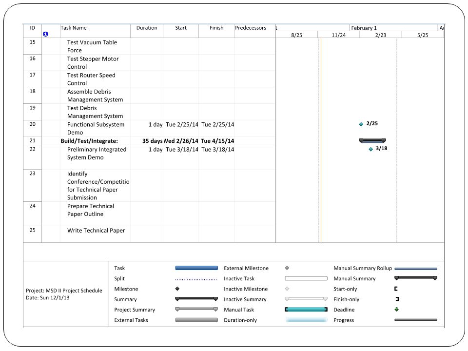
Preliminary MSD II Plan

66
Questions?

Similar presentations


![Implementing Administrative Systems? You need an Evolution, not a Revolution! UNIVERSITY OF WASHINGTON Copyright [your name] [year]. This work is the intellectual.](/15/4782169/big_thumb.jpg "Implementing Administrative Systems? You need an Evolution, not a Revolution! UNIVERSITY OF WASHINGTON Copyright [your name] [year]. This work is the intellectual.>")


>")


 Images Courtesy of Corning Tropel.>")


