Download presentation
Presentation is loading. Please wait.

1
5. 의료영상 및 PACS 2011. 4. 13 안병익(biahn99@gmail.com)
Mcomputing.tistory.com @LBSAHN
2
Medical Imaging Tech & PACS
CT MRI PET/CT PACS DICOM

3
Why use different methods of imaging ?
Cost Effectiveness A good guiding principle in many walks of life is … Always pick the simplest solution for your problem. In many cases the cheapest solution is the best. You do not need to give every pregnant mother in the country an MRI scan. The capital cost of installation varies widely: Ultrasound X-ray CT MRI PET £20k - £100k £500k - £1M £2M - £4M >£5M

4
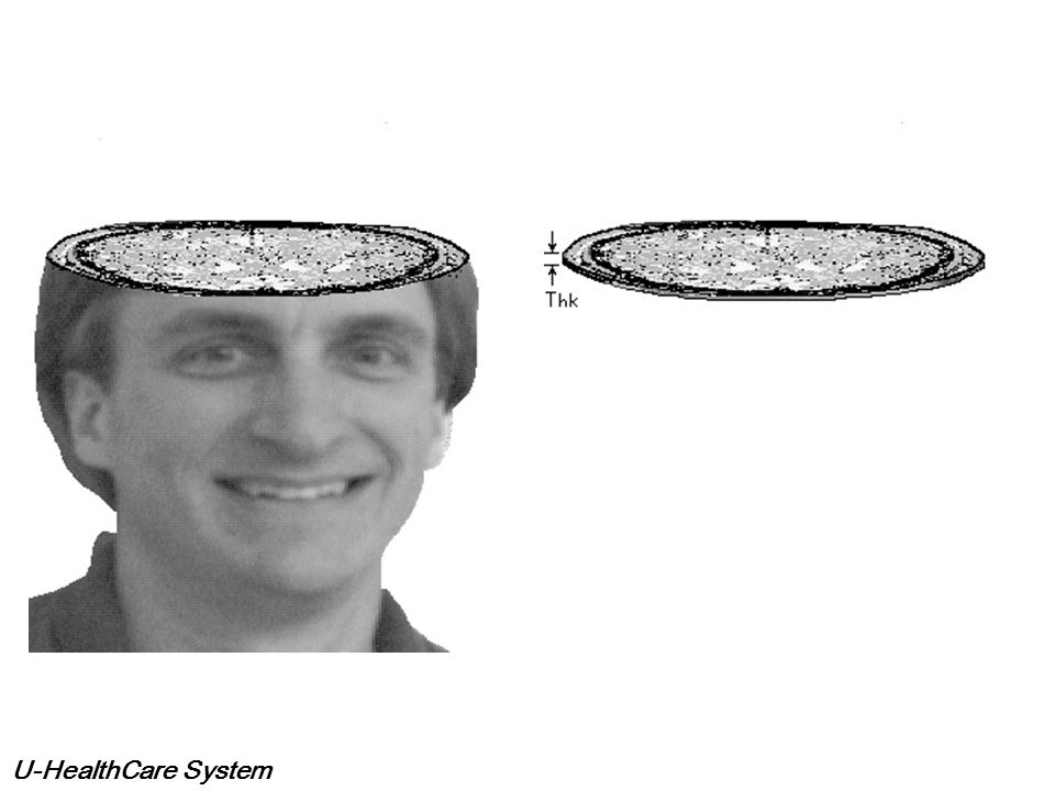
What is the CT? Mathematical transform to the measured data.
Reconstruct n dimension function (image) => projection data of n – 1 dimension Radon Transform (1917) “Two dimension and three dimension object can be reconstructed from the infinite set of projection data”. The First CT: 1973 in the U.S. 4 minutes scan, thickness of 10mm
 => projection data of n – 1 dimension. Radon Transform (1917) Two dimension and three dimension object can be reconstructed from the infinite set of projection data . The First CT: 1973 in the U.S. 4 minutes scan, thickness of 10mm.")
5
Concept of CT CT Algorithm
・Getting the shape by back projection of the projection data. ・For example, outward view is the quadrangle => it is the cylinder CT Algorithm

6
CT (From Picker) (From Siemens)
 (From Siemens)")
7
Basic principle of CT -Reconstruction of 2 dimensional image-
Projection Data curvilinear integral of absorption coefficient regarding Y X y y X-ray detector array Y X x object x X Blur X-ray tube Data Acquisition field Reconstruction field Simple Backprojection

8
Basic principle of CT -Reconstruction of 2 dimensional image-
Projection Data x y x X * Filtered Projection data Reconstruction Filter x ω or x Multidirectional Backprojection Filtered Backprojection

9
Reconstruction process

10
Reconstruction process
Data acquisition at angle : 0 – 180 degree Obtain F(u,v) and then 2D IFFT -> reconstruction Radon Transform is equivalent to Filtered backprojection !
 and then 2D IFFT -> reconstruction. Radon Transform is equivalent to Filtered backprojection !")
11
Simple Backprojection
Example of Simulation Model Image Simple Backprojection Filtered Backprojection

12
Magnetic Resonance Imaging

13
Magnetic Resonance Uses equipment producing magnetic fields from 0.5 Tesla to 3 Tesla Earths magnetic field is 50 microtesla Cost of equipment is approx £700k per Tesla

14
Obtaining the Data All atoms have a magnetic field or orientation
When placed in a strong magnetic field the atomic nuclei align with that field Pulses of Radio Frequency aimed at area of interest in the body Imparts high energy state to the nuclei of those areas Relaxation of that state produces resonance which can be detected Location and intensity will translate into pixel location and intensity

16
Slices

18
Image Processing

19
Image Manipulation and Enhancement
Two time frames T1 and T2 relate to percentages of nuclei which have resumed normal state T1 improves resolution T2 improves sensitivity Contrast media can be introduced fMR can monitor specific physiology

20
Anatomy or Physiology?

21
Using Data Manipulation

22
Image Manipulation

23
When Do We Use MRI? Excellent for soft tissue imaging
Resolution is good Does NOT use ionising radiation but does have some safety issues

24
MR Versus CT MR Digital manipulation Non-ionising Non-invasive
Good for soft tissue Can image physiology Technique can be altered to account for data required Expensive CT Digital manipulation Ionising Xrays Non-invasive Good for range of tissue types, soft tissue to a lesser extent Can only image physiology when used with other modalities Variation in technique possible Relatively Cheap

25
PET / CT System

26
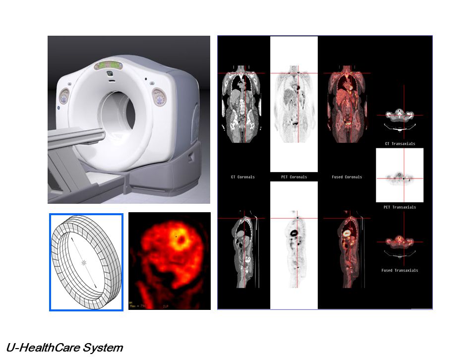
PET / CT 란 ? PET / CT란 양전자 방출 촬영기(Positron Emission Tomography)와 컴퓨터 단층촬영기(Computed Tomography)를 하나로 합친 장비이다. PET / CT 장비는 암 진단에 효과적으로 사용되고 특히 종양을 CT, 감마카메라 등에 비해 월등히 앞선 시기에 진단할 수 있게 되어 암의 조기 진단을 가능하게 한다. 검사시간을 크게 단축하여 환자의 고통을 덜어주고 환자에 대한 병원의 의료서비스의 질이 한층 높아질 것으로 예상된다.

27
PET / CT 란 ?? PET은 양전자 방출하는 방사성의약품을 이용하여 체내의 미세한 변화를 영상화 하는 최첨단 검사이고, 이용하는 약품에 따라 당 대사, 단백질 대사, 핵산대사, 혈류 등의 다양한 체내변화를 영상으로 얻을 수 있으며, 이중 포도당대사를 관찰하는 검사가 가장 흔히 쓰인다. PET/CT는 이러한 PET과 CT를 동시에 시행하는 검사이다. PET만 시행했을 때 생길 수 있는 정상조직에 의한 진단오류를 최소화하고 진단성능을 향상시킬 수 있게 한다.

29
PET / CT 검사원리 PET/CT에서는 양전자를 방출하는 포도당 유사체를 이용합니다. 인체 내에 주사 된 포도당 유사체는 암세포에 집적되고 방출된 양전자(+)는 주변의 전자(-)를 만나서 소멸반응을 일으킨 후 서로 반대방향을 가지는 511 KeV 에너지의 두 개의 감마선으로 변환됩니다. 이 감마선들은 PET/CT의 원형동시계측회로에서 검출되어서 컴퓨터에 위치 정보를 전달하게 되고 컴퓨터에서는 인체 내에 어느 곳에 이상이 있는지를 영상으로 표현해 줍니다.
는 주변의 전자(-)를 만나서 소멸반응을 일으킨 후 서로 반대방향을 가지는 511 KeV 에너지의 두 개의 감마선으로 변환됩니다. 이 감마선들은 PET/CT의 원형동시계측회로에서 검출되어서 컴퓨터에 위치 정보를 전달하게 되고 컴퓨터에서는 인체 내에 어느 곳에 이상이 있는지를 영상으로 표현해 줍니다.")
30
PET / CT 장점 암의 조기발견 암의 분포진단 암 치료 계획에 이용 검사시간의 감소
암이 어디까지 퍼져있는지 판단. 암의 재발진단. 암 치료 계획에 이용 암이 발견될 경우 , 바로 치료방침을 세울 수 있는 정보까지 제공받을 수 있다. 검사시간의 감소 최대 40% 절약하여 불편한 환자의 불편을 감소시키고 병원의 생산성도 높이고있다. 한 번의 촬영으로 전신을 검사할 수 있다.

31
PET / CT 단점 분화도가 좋은 간암이나 조기위암 등의 진단성능은 조금 떨어진다.
신장 , 요관 , 방광 , 전립선 등 비뇨생식기계 암은 소변으로 인해 진단에 주의해야 한다. 대사항진이 높지 않은 3~4 mm 이하의 작은 암은 발견되지 않을 수도 있다는 한계점을 고려해야 한다 .

32
PET / CT로 알 수 있는 질환 PET/CT 의 가장 대표적인 적응증은 암 입니다 .

33
PET / CT 검사종류 전신 PET / CT 뇌신경계 PET / CT 심장 PET / CT

34
전신 PET / CT 방사선의약품을 팔에 정맥주사하고 40분 후에 몸 전체를 CT촬영을 하고, 이어서 PET검사를 시행한다.
폐암, 유방암, 대장암, 두경부암, 림프종, 흑색종, 근골격계암, 자궁경부암, 난소암 등의 조기발견 및 전이여부, 양성과 악성 종양의 감별, 암의 병기결정, 재발여부판정, 항암화학요법제와 수술의 치료효과 한정, 환자의 예후 예측등이 가능하다.

35
신세포암으로 수술 후 별 증상 없었으나, PET/CT시행 후 복부에 임파선 재발을 확인할 수 있다.

36
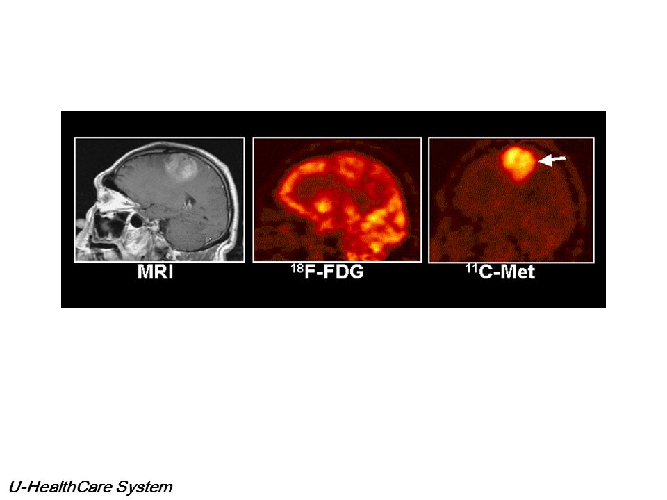
뇌신경계 PET / CT 간질환자의 수술전 검사, 파킨슨씨병, 치매(알츠하이머병)의 진단. 뇌종양, 뇌혈관질환의 진단에 사용한다. 기억력 감퇴 등 치매가 의심되는 증상이 있어 이를 조기발견해서 질병진행 억제 치료를 한다면 치매를 예방하는데 도움이 됩니다. 일부 운동신경계 질환의 감별진단을 원할 때 이용한다. 뇌암 진단 받고 방사선치료를 받은 뒤 잔존하는 암이 있는지의 여부를 MRI에서 알기 어려울 때 이용한다.

38
심장 PET / CT 협심증과 심근경색과 같은 관상동맥 질환을 진단한다.
허혈성 심장질환에서 보다 정확한 생존심근부위의 판정을 원할 때 심근 생존능력을 평가하여 치료방법을 결정하는데 시용한다.

39
What is PACS ? P: Picture, Images & Reports
A: Archive, Online, Near line, Offline C: Communication, Networking, Transfer Protocols S: System, Components & Architecture PACS: for storage and distribution of images and information when necessary

40
PACS: Small or Large Web Server Distribution

41
Scale of PACS No. of Beds in Hospital/ Exams per year
No. of Modalities No. of Switches Considerations: System connectivity, expandability, reliability and cost-effectiveness Connection among various hospital information system, open architecture, Data migration is painful enough if you have money

42
Types of images 1D, 2D, 3D, 4D Different DICOM Modality type: Cardiac / PET / 4D U/S….. Image size: Resolution and bit depth Image quality: Bit Depth and resolution Color / Monochromatic Exam. Size: image size x no. of images Structured Reports New DICOM IOD: Endoscopic & Microscopic images / ECGs / Security Profiles….. IOD=information object definition; Mammo CAD use SR output; DICOM waveform IOD; DICOM visible light IOD; Digital Envelop over Digital Signature

43
1D, 2D, 3D, 4D, fusion

44
1D, 2D, 3D, 4D, fusion

45
Image Resolution/ Bit depth
U/S DF CR CR Mammogram 256 x 256 8 bit 65 KBytes 1k x 1k 10 bit 1.25 MByte 2k x 2.5k 12 bit 7.5 MByte 4k x 5k 12 bit 30 MByte

46
Properties of image Bit depth Grayscale or color Resolution in pixel
Example image size of mammogram = 4k x 5k x 12 bit = 30 MB Microcalcification need 130 µm resolution
![]()
47
PACS Architecture

48
PACS – Central Architecture
DICOM Modality Diagnostic Workstations (DICOM) Clinical Workstations (DICOM) Image Server (RAID) Gateway or Frame Grabber Diagnostic Workstation Non-DICOM Modality Film Digitizer Web Server Data Base Server CR/ DR QA Workstation Archive Computed Radiography or DR RIS
 Clinical. Workstations (DICOM) Image. Server. (RAID) Gateway or. Frame Grabber. Diagnostic. Workstation. Non-DICOM. Modality. Film. Digitizer. Web Server. Data Base. Server. CR/ DR QA. Workstation. Archive. Computed. Radiography. or DR. RIS.")
49
Central Architecture Image Server and Database Manager is the HEART
Any image, any where, any time Unique central copy Easy update of data Requires high performance servers Potential single point of failure at server Bandwidth demanding

50
PACS – Distributed Architecture
DICOM Modality Gateway or Frame Grabber Diagnostic Workstations (DICOM) Clinical Workstations (DICOM) Web Server Non-DICOM Modality CR QA Workstation Diagnostic Workstation Film Digitizer Data Base Server Archive Computed Radiography RIS
 Clinical. Workstations. (DICOM) Web Server. Non-DICOM. Modality. CR QA. Workstation. Diagnostic. Workstation. Film. Digitizer. Data Base. Server. Archive. Computed. Radiography. RIS.")
51
Distributed Architecture
Exams are routed from modality to selected workstations Complex routing algorithms based on department / user preference Difficult to support concurrent review of images Less destructive for failure at database server

52
Components of PACS HIS/ RIS Broker ePR gateway Database Server
Image Server (RAID) Long Term/ Near line Archive Networks Digitizer
 Long Term/ Near line Archive. Networks. Digitizer.")
53
Components of PACS Acquisition Gateways Non-DICOM modality gateway
DICOM Print Server Media Server Reporting Server Monitor QC Server Web Server Workstations

54
PACS layout 1

55
PACS layout 2 All in blue must mention

56
PACS layout 3

57
PACS Components Image Server (RAID) ePR gateway Enterprise Archive
DICOM Modality Diagnostic Workstations (DICOM) Through Acq. gateway W/S QA Server Clinical Workstations (DICOM) Image Server (RAID) Gateway or Frame Grabber Diagnostic Workstation Non-DICOM Modality Film Digitizer Web Server Data Base Server CR/ DR QA Workstation LTS Archive SAN/NAS Computed Radiography or DR Media Server Broker for RIS/HIS
 Through Acq. gateway. W/S QA Server. Clinical. Workstations (DICOM) Image. Server. (RAID) Gateway or. Frame Grabber. Diagnostic. Workstation. Non-DICOM. Modality. Film. Digitizer. Web Server. Data Base. Server. CR/ DR QA. Workstation. LTS Archive. SAN/NAS. Computed. Radiography. or DR. Media Server. Broker for. RIS/HIS.")
58
Acquisition (DICOM) Gateway
HIS/RIS Interface (Broker) DG RIS W/S PCs CR QA Film Digitizer Frame Grabber CT MR R&F NM CR XRAY US
 DG. RIS. W/S. PCs. CR QA. Film. Digitizer. Frame. Grabber. CT. MR. R&F. NM. CR. XRAY. US.")
59
Role of Acquisition gateway
Compression/ decompression and security Check the images for integrity Convert to PACS format (header, byte-order, matrix size) Queue for images (priority) to database server (background) Share the workload and no point of failure for multiple Acquisition gateway
 Queue for images (priority) to database server (background) Share the workload and no point of failure for multiple Acquisition gateway.")
60
Database Server and Image Server
RAID Database Server HIS/RIS Interface (Broker) DG RIS W/S PCs CR QA Film Digitizer Frame Grabber CT MR R&F NM CR XRAY US
 DG. RIS. W/S. PCs. CR QA. Film. Digitizer. Frame. Grabber. CT. MR. R&F. NM. CR. XRAY. US.")
61
Database Server (PACS controller)
The Heart of the system Integration cross point between HIS/RIS and PACS (status update) Create and manages patient folders Manage reading worklists and user profiles Manage data transfer within the system Support data mining and teaching folders
 Create and manages patient folders. Manage reading worklists and user profiles. Manage data transfer within the system. Support data mining and teaching folders.")
62
Image Server (RAID) Online (rapid access) exam storage and distribution device Support simultaneous exam input and output transfer operations Up to Three months of storage capacity Scalable capacity

63
What is RAID Redundant Array of Independent Disks
Bandwidth equal to sum of disk transfer rates Highest speed disk storage available Hot Swap 2 MB/s 1 2 3 4 5 6 16 MB/s 7 8 Image Parity Disk Array

64
RAID 5 configuration If disk fails, disk can be rebuilt- fault tolerant High data transfer rate for read, write slower Min. 3 disks to start Array capacity is N-1

65
Bandwidth Bandwidth is a measure of the information (data) carrying capacity of a network 10/100/1000 MB/sec Information Flow Data Pipe (Network)
")
66
Network Bottleneck The bandwidth of an information delivery system is limited to the bandwidth of the slowest component in the system Network Bottleneck

67
Data Compression Data compression reduces the information rate
a network must support Uncompressed Data Compressed Data

68
Lossless Image Compression
I - D = 0 I D Decompressed image is identical to original image JPEG lossless compression Average compression of 2:1 for x-ray images

69
JPEG 2000 Compression Selected parts of the image can be defined as Regions of Interest, they can then be delivered before other parts of the image, or losslessly, whilst other parts of the image that are less critical use normal lossy compression JPEG 2000 codestream can be ordered to deliver images of lower resolution before the full image can be transmitted Motion JPEG 2000 does not have any form of extrapolation (and hence potential distortion) in the time domain. Each frame is a separate JPEG 2000 coded image
 in the time domain. Each frame is a separate JPEG 2000 coded image.")
70
JPEG 2000 images

71
Storage Device (Long Term)
RAID Database Server MOD DLT HIS/RIS Interface (Broker) DG RIS W/S PCs CR QA Film Digitizer Frame Grabber CT MR R&F NM CR XRAY US
 DG. RIS. W/S. PCs. CR QA. Film. Digitizer. Frame. Grabber. CT. MR. R&F. NM. CR. XRAY. US.")
72
Types of storage media Media DVD MOD DLT 9840 AIT2 GB Cost
WORM DLT 9840 AIT2 GB 3.8 5.2 35 20 50 Cost Less Expen. Expen. Cheap Most Expen. Load + Assess Very fast 113 sec 15 sec 45 sec Max. T rate MB/s 5 5.1 10 6

73
Long Term Archive Used to store digital data for longer periods of time Storage ranges from 100 MB to 10 TB Optical disk most common media - 5 1/4” MOD - 2.6 GB and 5.2 GB Capacity DLT used for longer term storage and redundancy ISP module

74
Storage Device (Near line)
RAID Database Server SAN/NAS MOD DLT HIS/RIS Interface (Broker) DG RIS W/S PCs CR QA Film Digitizer Frame Grabber CT MR R&F NM CR XRAY US
 DG. RIS. W/S. PCs. CR QA. Film. Digitizer. Frame. Grabber. CT. MR. R&F. NM. CR. XRAY. US.")
75
Storage Area Network SAN is a high-speed sub-network of shared storage devices Contains storage device (disk) for storing data SAN's architecture works in a way that makes all storage devices available to all servers Use of Fiber Channel High scalability for additional storage and redundant networks PCs Storage devices

76
Network Area Storage NAS is a class of dedicated hard disk-based storage devices which provide LAN users with additional disk storage through a standard network connection In most cases, a NAS device (or NAS server) receives an IP address, connects to the LAN through an Ethernet cable, and resides on the LAN as an independent network device Users are not demanding the server's processing time for mundane storage tasks -- often improving the performance of local application servers NAS systems also include some onboard memory (RAM) to cache network data to or from the disks
 receives an IP address, connects to the LAN through an Ethernet cable, and resides on the LAN as an independent network device. Users are not demanding the server s processing time for mundane storage tasks -- often improving the performance of local application servers. NAS systems also include some onboard memory (RAM) to cache network data to or from the disks.")
77
SAN Vs NAS Difference between NAS and SAN is subtle
NAS devices are big, single purpose storage appliances that you plug into network NAS sits between your application server and your file system As perform only 1 task, can serve files very fast NAS is network-centric SAN is a defined architecture that sits between your file system and your underlying physical storage SAN is data-centric

78
Display MOD DLT SAN/NAS DG RIS W/S PCs CR QA CT MR R&F NM CR XRAY US
RAID HIS/RIS Interface (Broker) Database Server MOD DLT Diagnostic W/S Dedicate W/S SAN/NAS DG RIS W/S PCs CR QA Film Digitizer Frame Grabber CT MR R&F NM CR XRAY US
 Database. Server. MOD. DLT. Diagnostic W/S. Dedicate W/S. SAN/NAS. DG. RIS. W/S. PCs. CR QA. Film. Digitizer. Frame. Grabber. CT. MR. R&F. NM. CR. XRAY. US.")
79
Workstations Four Primary Categories
- Advanced Analysis: Used by specialists for advanced diagnosis - 3D, volume rendering Diagnostic: For primary diagnosis; located in reading rooms; high-end 2K monitors Clinical: Used by clinicians and staff to consult; ICU / ER applications; less costly than diagnostic; 1K monitors At Home Review: low-end; PC based; cost-effective; review application; lossy compressed for faster transmit

80
Standalone Vs direct PACS w/s
Standalone Workstation Direct PACS Client Workstation Hard Disk Storage Yes, varies Minimal Query PACS number All PACS system (CT, ACC, Angio.) Single PACS system (ACC PACS) Retrieval mechanism DICOM Q/R and association made with different vendors Direct attached, same vendor Retrieval time Slower Faster Diagnostic value Depends on Monitor Grade and Modules like MPR, 3D etc Suggested usage for meeting/museum purpose for single modality image reviewing and reporting like Radworks in U/S Rm Direct PACS workstation for reporting
 Single PACS system (ACC PACS) Retrieval mechanism. DICOM Q/R and association made with different vendors. Direct attached, same vendor. Retrieval time. Slower. Faster. Diagnostic value. Depends on Monitor Grade and Modules like MPR, 3D etc. Suggested usage. for meeting/museum purpose. for single modality image reviewing and reporting like Radworks in U/S Rm. Direct PACS workstation for reporting.")
81
Web distribution High availability, low cost
Reports / select images to referring physician desktop Point of integration with electronic patient record Lossy compression for performance Potential for TeleRadiology Security issues to be resolved

82
RIS, HIS, ePR and PACS integration

83
Broker HIS/RIS and PACS interface
DG RIS W/S PCs CR QA Film Digitizer Frame Grabber CT MR R&F NM CR XRAY US

84
Hospital Information System
Support clinical and medical patient care activities in the hospital Administer the hospital’s daily business transactions like finance, payroll etc Evaluate hospital performances and costs and make long-term forecast

85
Clinical System in HA, HK
Patient Administration In-Patient and Out-Patient Administration System Accident & Emergency Information System Medical Record Abstract System Medical Record Tracking System Clinical Support Laboratory Information System Radiology Information System Pharmacy Management System Dietetics Catering Management System Clinical Management Clinical Management System (In-Patient) Discharge Summary Clinical Management System (Out-Patient) Electronic Patient Records Clinical Data Analysis and Reporting System
 Discharge Summary. Clinical Management System (Out-Patient) Electronic Patient Records. Clinical Data Analysis and Reporting System.")
86
Non-Clinical System in HA
Human Resources and Payroll Systems Hospital Based Financial System Materials Management System Patient Billing and Revenue Collection System Executive Information System Code 9 and view codes

87
Radiology Information Systems
Similar to HIS but of smaller scale Interfaces to PACS based on HL7 Department administrative management - Scheduling and Film tracking - Resource management and reporting - Monitor patient status Link to Hospital Information System (HIS) - Billing and Master Record Link to Clinical Management System (CMS) - Prefetch for Clinical visit - ePR integration
 - Billing and Master Record. Link to Clinical Management System (CMS) - Prefetch for Clinical visit. - ePR integration.")
88
RIS workflow Exam Order Exam Scheduled Web distribution to referring
physicians RIS Modality Worklist Demographics Downloaded Patient Exam Is Performed Images copied on web-server Order Event Images transferred in STS Database server /Archive Prefetch Exams From Storage PACS Worklist Updated Images / Prior Reports Exam Read Dictated status Image migration STS to LTA Final report available Report Verified Preliminary status Exam Transcribed

89
Broker service Database server DR HA HIS CR HA RIS HA CMS US DF Mitra
ADT CR Mitra PACS Broker interface HA RIS Appt., X-ray request HA CMS Clinical visit US DF Database server Modalities: Get WORKLIST Get REPORT, Get INFO

90
Broker service A restricted access account will be created at Sybase that gives limited authority for the DICOM Broker solely for the purpose of the interfaces In general, for data flow from RIS to the Broker, the RIS write the supported events to the table, and the Broker polls against the events table and calls the associated stored procedures for the conversion to DICOM messages

91
Broker service Broker main function: - Worklist generation
- Reports storage Registration + Post exam data capture (RIS) Acc # generation + call broker for update Need SOME time!! Modalities query Broker for worklist update Broker poll RIS event table and convert to DICOM info
 Acc # generation + call broker for update. Need SOME time!! Modalities query Broker for worklist update. Broker poll RIS event table and convert to DICOM info.")
92
ePR Architecture Selected images from individual hospital’s PACS are sent make use of the ePR record indexing and browsing capabilities to read the radiology images through CMS workstations

93
Data Flow Diagram RIS ePR HA system Appointment Attendance
Exam records Reports (15mins) CMS RIS operational data ePR Web Server PACS Attendance Exam & workload units (daily) RIS statistical data Data warehouse Non clinical system
 CMS. RIS operational data. ePR. Web Server. PACS. Attendance. Exam & workload units (daily) RIS statistical data. Data warehouse. Non clinical system.")
94
Characteristics of ePR
Near instant image review Web distribution can be within hospital, to other hospitals or even private clinics TeleRadiography possible Update of patient information Lossy Vs lossless Broken pathway 15 minutes time lag

95
Guidelines for HIS, RIS, PACS interface
Each system remain unchanged in its configuration and function, only data are shared Identify the subset data to be shared and set up access rights/ authorization Convert the subset data to HL7 standard Define transfer protocol (TCP/IP or DICOM)
")
96
Typical patient and data flow
Admission: Patient registration, notify HIS (HL7) Order entry/Arrival: Schedule exam and notify RIS Broker notified and PACS database server updated (prefetch) DICOM worklist to modality Exam completed: data to DICOM gateway (MPPS) Information/images to database/image server through gateway (DICOM store) Images stored in PACS archive Images to workstations from PACS archive Dictation, transcription etc: workstation to RIS/PACS RIS reporting and PACS updated for reports Transfer: HIS/RIS to PACS, images to other PACS Discharge: HIS/RIS to PACS, images rub out
 Order entry/Arrival: Schedule exam and notify RIS. Broker notified and PACS database server updated (prefetch) DICOM worklist to modality. Exam completed: data to DICOM gateway (MPPS) Information/images to database/image server through gateway (DICOM store) Images stored in PACS archive. Images to workstations from PACS archive. Dictation, transcription etc: workstation to RIS/PACS. RIS reporting and PACS updated for reports. Transfer: HIS/RIS to PACS, images to other PACS. Discharge: HIS/RIS to PACS, images rub out.")
97
Mobile PACS

98
What is DICOM? The standard for Digital Imaging and Communications in Medicine. Developed by the National Electrical Manufacturers Association (NEMA) in conjunction with the American College of Radiology (ACR). Covers most image formats for all of medicine. Specification for messaging and communication between imaging machines.
 in conjunction with the American College of Radiology (ACR). Covers most image formats for all of medicine. Specification for messaging and communication between imaging machines.")
99
A little history The first version was ACR-NEMA, released in 1985.
Its goal in developing a standard was To enable users to retrieve images and associated information from digital imaging equipment in a standard format using point-to-point connection. To hide differences same across multiple image equipment manufacturers. To handle developing network and image standarts, a new standard, DICOM, was proposed in 1981.

100
DICOM Application Domain
MAGN ETOM Information Management System Storage, Query/Retrieve, Study Component Query/Retrieve Results Management Print Management Media Exchange LiteBox

101
Summary of DICOM Features
NETWORK PROTOCOL DICOM incorporates negotiation to permit peers to agree on the functions to be performed MESSAGE ENCODING DICOM defines 24 data types (V2.0 had 4) DICOM message encoding includes JPEG compression (17 varients) DICOM supports multiple character repertoires
 DICOM message encoding includes JPEG compression (17 varients) DICOM supports multiple character repertoires.")
102
Summary of DICOM Features
OBJECT DATA MODEL DICOM is based on a completely specified data model DICOM includes a robust UID mechanism DATA DICTIONARY DICOM includes a large number of new data elements SERVICE CLASSES DICOM defines classes of service for specific applications (e.g. image management, printing) and conformance levels
 and conformance levels.")
103
DICOM Objects Things such as images, reports, and patients are all objects and are called information objects. Two kinds of objects in DICOM: Composite objects (Old objects inherited from NEMA). Normalized objects (New objects defined in DICOM). All objects and their format constitutes Data Dictionary. DICOM uses UIDs to identify information objects, such as the images, reports, or transfer syntaxes. The form of the UID conforms to an international standard. is the root and the same for every DICOM UID. Example: UID for the DICOM explicit VR little endian transfer syntax is
. Normalized objects (New objects defined in DICOM). All objects and their format constitutes Data Dictionary. DICOM uses UIDs to identify information objects, such as the images, reports, or transfer syntaxes. The form of the UID conforms to an international standard is the root and the same for every DICOM UID. Example: UID for the DICOM explicit VR little endian transfer syntax is")
104
DICOM Service Classes Composite Verification Storage Query/Retrieve
Study Content Notification Normalized Patient Management Study Management Results Management Basic Print Management

105
Hardcopy Image Reading + Dictation/Transcription (Use Case 1)
Hardcopy Reading Hardcopy DICOM Print as Seen at Modality Reporting: RIS-Based Transcription / Validation of Narrative Report RIS-Based Report Storage and Management Send Reports Query Prior Reports

106
Hardcopy Image Reading + Dictation/Transcription (Use Case 1)
Report Storage / Mgmt. Report Repository RIS Electronic Report Paper print/ Mail/ Fax/ send Narrative Info Only Electronic Report query Acquisition Transcription & Correction print Validation Filming Film Archive Hardcopy Interpretation & Dictation manual network DICOM HL7/other optional

107
Hardcopy and Softcopy Image Reading + Dictation/Transcription (Use Case 2)
Hardcopy Reading Hardcopy DICOM Print as Seen at Modality Softcopy Reading Hardcopy DICOM Print as Seen During Softcopy Reading Reporting: RIS-Based Transcription / Validation of Narrative Report RIS-Based Report Storage and Management Send Reports Query Prior Reports

108
Hardcopy and Softcopy Image Reading + Dictation/Transcription (Use Case 2)
store Selected Images Softcopy Interpretation & Dictation Report Storage / Mgmt. Report Repository RIS Electronic Report Paper print/ Mail/ Fax/ send Electronic Report Narrative Info Only query Acquisition Transcription & Correction print Validation Filming Film Archive Hardcopy Interpretation & Dictation manual network DICOM HL7/other optional

109
Acquisition Workflow Support + Burn CD/DVD (Use Case 3)
Image Acquisition: RIS-based Acquisition Workflow Support (Modality Worklist) Image Reading: Hardcopy Reading Hardcopy DICOM Print as Seen at Modality Softcopy Reading Hardcopy DICOM Print as Seen During Softcopy Reading DICOM Store Images -> Burn CD/DVD Reporting: RIS-Based Transcription / Validation of Narrative Report RIS-Based Report Storage and Management Send Reports Query Prior Reports Optional DICOM Store Reports -> Burn CD/DVD
 Image Reading: Hardcopy Reading. Hardcopy DICOM Print as Seen at Modality. Softcopy Reading. Hardcopy DICOM Print as Seen During Softcopy Reading. DICOM Store Images -> Burn CD/DVD. Reporting: RIS-Based Transcription / Validation of Narrative Report. RIS-Based Report Storage and Management. Send Reports. Query Prior Reports. Optional DICOM Store Reports -> Burn CD/DVD.")
110
Hardcopy and Softcopy Image Reading + Dictation/Transcription (Use Case 3)
Modality Worklist store Selected Images Softcopy Interpretation & Dictation Report Storage / Mgmt. Electronic Report Report Repository RIS Paper print/ Mail/ Fax/ send Electronic Report Narrative Info Only query Acquisition Transcription & Correction print Burn CD/DVD Off-Line Archive Validation store Filming Film Archive manual network DICOM HL7/other optional Hardcopy Interpretation & Dictation

111
PACS for Management of DICOM Persistent Objects (Use Case 4)
Image Acquisition: RIS-based Acquisition Workflow Support (Modality Worklist) Image Reading: Hardcopy Reading Hardcopy DICOM Print as Seen at Modality Softcopy Reading Hardcopy DICOM Print as Seen During Softcopy Reading DICOM Store Images for Burning CD/DVD PACS-based Storage and Management of DICOM Persistent Objects Archive Imaging Studies Query Prior Imaging Studies Reporting: RIS-Based Transcription / Validation of Narrative Report RIS-Based Report Storage and Management Send Reports Query Prior Reports Optional DICOM Store Reports for Burning CD/DVD
 Image Reading: Hardcopy Reading. Hardcopy DICOM Print as Seen at Modality. Softcopy Reading. Hardcopy DICOM Print as Seen During Softcopy Reading. DICOM Store Images for Burning CD/DVD. PACS-based Storage and Management of DICOM Persistent Objects. Archive Imaging Studies. Query Prior Imaging Studies. Reporting: RIS-Based Transcription / Validation of Narrative Report. RIS-Based Report Storage and Management. Send Reports. Query Prior Reports. Optional DICOM Store Reports for Burning CD/DVD.")
112
PACS for Management of DICOM Persistent Objects (Use Case 4)
Modality Worklist store Object Storage / Mgmt. Electronic Report Electronic Report Selected Images Report Repository RIS Paper print/ Mail/ Fax/ send Softcopy Interpretation & Dictation query Narrative Info Only Transcription & Correction Image Repository PACS Acquisition store Validation print store q/r store Off-Line Archive Filming Burn CD/DVD Film Archive Hardcopy Interpretation & Dictation manual network DICOM HL7/other optional

Similar presentations


 Project SISU Medical Systems July 17, 2006.>")


