Download presentation
Presentation is loading. Please wait.

1
In Corporation With Jawwal
Graduation Project Indoor Cell Planning For An-Najah Educational National Hospital In Corporation With Jawwal Superviser Dr.Allam Mousa Prepared by Mohammed Donbok Haitham Fahed

3
Problems’ Description
This project discussed the problems existing in An Najah Educational National Hospital which are poor quality calls, drop calls and call setup failure. These problems are because of weak signal strength.

4
Project’s Goal Solve the problems inside the building of An Najah Educational National Hospital which is considered to serve the areas north of the West Bank, with an acceptable range of coverage, capacity, quality.

5
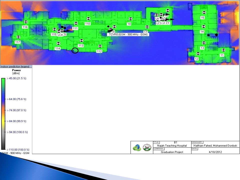
Problem Solution Design a system that will distribute a uniform strong signal inside the building, from the indoor cell, using indoor system in order to provide sufficient coverage, quality, capacity and dominance. RX-Level Deep Indoor -45 dBm to -64 dBm Indoor -65 dBm to -74 dBm InCar -75 dBm to -84 dBm Outdoor -85 dBm to -94 dBm Bad Service -95 dBm to -110 dBm

6
System Components 1- Radio Base Station (RBS) : Ericsson 2308, 4 TRUs, 34 dBm output power.
 : Ericsson 2308, 4 TRUs, 34 dBm output power.")
7
Cont’d (System Components)
2- Antennas : Omni and Directional Antennas. 3- Splitters : 2,3 and 4 ports. 4- Cables: ½in with 7dB/100m loss.

8
The Design 1- Passive or Active Distributed Antenna Systems?
Two system types can be used for indoor solution, Active DAS or Passive DAS. In this project Passive DAS has been used for these reasons: Components from different manufacturers are compatible. It can be installed in harsh environment. No high data rate needed. No DC power supply is needed for the equipments.

9
Cont’d ( The Design ) 2- Capacity Dimensioning.
These conditions should be determined to calculate the number of channels that are needed to solve the capacity problem. Number of subscriber = 900 subscribers. Types of subscriber : Normal = 25 mE. Grade of service (Call Blocking Rate ) = 2%.
 = 2%.")
10
Cont’d (Capacity Dimensioning)
Total Load = number of Subscribers X Load Per User Total Load = 900 X 0.025 ≈ 23 E According to Erlang B-Table with 2% GOS, 32 channels are needed.

11
Cont’d (Capacity Dimensioning)
Every TRUs can carry 8 channels so 32/8 = 4 TRUs are needed. The system uses 3 channels for control so 32 – 3 = 29 traffic channels.

12
Indoor Link Calculations ( By Hand )
1-Link Budget: The power that just comes out antenna can be calculated according to this equation:

13
Cont’d (Indoor Link Budget)
First Try Antenna Locations in B1

14
Cont’d (First Try) Power Splitting
 Power Splitting")
15
link Budget Calculations for B1 Floor
Antenna # RBS output power (dBm) Cable Length (m) 2 Port Splitter 3 Port Splitter 4 Port Splitter TX Power (dBm) B1 TX-10 34 25 11 6 1 7.95 TX-11 7.32 TX-12 5.50 TX-13 5.64 TX-14 4 3 3.03 TX-15 2.40 TX-16 0.27 TX-17 2 -1.19 TX-18 -0.98 TX-19 -2.10 TX-110 -3.15 Basement one Antenna Loss in Cable Loss in splitter Total Loss Tx (antenna Tx 1-0 1.2 9.3 10.5 5 Tx 1-1 Tx 1-2 2.5 11.8 3.7 Tx 1-3 3.2 12.5 3 Tx 1-4 12.71 15.21 0.29 Tx 1-5 3.1 15.81 -0.31 Tx 1-6 15.91 -0.41 Tx 1-7 3.8 11 14.8 0.7 Tx 1-8 4.1 15.1 0.4 Tx 1-9 4.9 15.9 -0.4 Tx 1-10 5.1 16.1 -0.6 link Budget Calculations for B1 Floor
 Cable Length (m) 2 Port Splitter. 3 Port Splitter. 4 Port Splitter. TX Power (dBm) B1. TX TX TX TX TX TX TX TX TX TX TX Basement one. Antenna. Loss in Cable. Loss in splitter. Total Loss. Tx (antenna. Tx Tx 1-1. Tx Tx Tx Tx Tx Tx Tx Tx Tx link Budget Calculations for B1 Floor.")
16
Cont’d (Indoor Link Budget)
Final Design Antenna Location in B1

17
Power Splitting

18
link Budget for B1 Floor Antenna # RBS output power (dBm)
Cable Length (m) 2 Port Splitter 3 Port Splitter 4 Port Splitter TX Power (dBm) B1 11 34 63 10 35 1 2 7.47 12 18 8.66 13 9 3 7.53 14 15 20 6.76 16 5 48 10.07 17 22 11.89 12.03 19 13.22 112 113 11.05 110 40 28 6.81 111 7.79 114 21 7.30 115 7 8.28 116 117 6.39 link Budget for B1
 2 Port Splitter. 3 Port Splitter. 4 Port Splitter. TX Power (dBm) B link Budget for B1.")
19
Lifts link Budget Antenna # RBS output power (dBm) Cable Length (m)
2 Port Splitter 3 Port Splitter 4 Port Splitter TX Power (dBm) LA1 34 1 2 19.43 LA2 LC1 40 3 17.25 LC2 LC3 41 17.18 LC4 42 18.87 LC5 43 18.80 LB1 63 25 17.41 LB4 24 17.48 Lifts link Budget
 LA LA2. LC LC2. LC LC LC LB LB Lifts link Budget.")
20
Cont’d (Indoor Link Calculations)
2- Path loss Calculations FSPL : Free Space Path Loss ( dB ) d: Distance in (Km) f: frequency ( MHz)
 d: Distance in (Km) f: frequency ( MHz)")
21
Path Loss Samples Of Basement Two
Floor Point # TX Power (dBm) EIRP (dBm) Distance (m) Freq. (MHz) FSPL (dB) # of walls Loss In Walls RX Power (dBm) B2 P212 10.47 12.47 09.60 950 -51.7 4 -12.80 -52.07 P210 11.66 13.66 11.30 -53.1 1 -3.20 -42.69 Path Loss Samples Of Basement Two
 EIRP (dBm) Distance. (m) Freq. (MHz) FSPL. (dB) # of walls. Loss In Walls. RX Power (dBm) B2. P P Path Loss Samples Of Basement Two.")
22
Software Results 1- Link budget. Antenna # Hand Calculations
iBwave Calculations Difference 115 8.82 dBm 7.76 dBm 1.06 dB Why

23
2- Path Loss Sample Hand calculation iBwave calculation Results p212
-52 dBm -51 to -54 dBm Deep indoor

30
Conclusion Indoor systems can be a solution if the coverage, quality and capacity from outdoor cells are weak. The indoor system will radiate a dominant signal inside a building. The way of splitting affects on RX-signal. The design process includes: capacity dimensioning, choosing the components, deciding the target coverage level and distributing the antennas inside the building.

31
Cont’d (Conclustion) This design solve the existing problems completely which means that the goal of this project has been achieved. The most important areas inside the hospital have a deep indoor signal level ( >-64 dBm ). The design can serve 900 subscribers.
. The design can serve 900 subscribers.")
32
Questions

33
BIG THANKS AN-Najah National University JAWWAL COMPANY

Similar presentations


 Grants Chapter 6.>")
