Download presentation
Presentation is loading. Please wait.

1
By Shadia M.S.Elayyat

2
Objective Review Type of materials Type of semiconductor P-N junction Thin film Definition Type Thin film deposition Application References

3
Objectives The main objectives of this research are:- Study the characteristics of the materials Study the characteristics of the materials Study P-N junction Study P-N junction Discus and study the thin film deposition Discus and study the thin film deposition Study the application and uses of thin film Study the application and uses of thin film

4
Materi als Condu ctor Semicon ductor Insul ator plastics, paper, glass gold, silver, nickel, iron. Silicon, Germani um

5
Conductor mostly metals have the highest conductivities The conductivity decrease as the temperature increase

6
Insulator have high resistivity does not conduct an electric current under the influence of an electric field Example : Plastics Paper glass

7
semiconductor Semiconductors are materials whose electrical properties lie between Conductors and Insulators. Some common semiconductorsSome common semiconductorselemental Si - Silicon (most common) Ge - Germanium compound GaAs - Gallium arsenide GaP - Gallium phosphide AlAs - Aluminum arsenide AlP - Aluminum phosphide InP - Indium Phosphide
 Ge - Germanium compound GaAs - Gallium arsenide GaP - Gallium phosphide AlAs - Aluminum arsenide AlP - Aluminum phosphide InP - Indium Phosphide.")
8
The resistivity of the semicond uctor materials decrease as the temperatu re increase as shown if the figure

9
Valance Band The outermost orbital of an atom, where electrons are so tightly bounded that, they can not be removed as free electron Conduction Band This is the highest energy level or orbital in outer most shell, in which electrons are free enough to move. Band Gap There is one energy gap separates these two bands, - the valance band and conduction band. This gap is called forbidden energy gap Metal very small energy gab Semiconductor moderate E.G Insulator Large energy gab

10
The electrical conductivity at room temperature is quite different for each of these three kinds of materials Metals have the highest conductivities followed by semiconductors and then by insulators insulators

11
Two type of semiconductor Intrinsic( undoped ) semiconductor: the number of excited electrons and the number of holes are equal: n = p Type of semiconduc tor
 semiconductor: the number of excited electrons and the number of holes are equal: n = p Type of semiconduc tor")
12
Extrinsic semiconductor : is a semiconductor that has been doped. Doping involves adding dopant atoms to an intrinsic semiconductor, which changes the electron and hole carrier concentrations of the semiconductor at thermal equilibrium. an extrinsic semiconductor classify it as either an n-type or p-type semiconductor

14
P-type semiconductor is an intrinsic semiconductor in which an impurity acting as an acceptor(number of holes grater than number of electrons ) N-type semiconductor is an intrinsic semiconductor in which a donor impurity has been intentionally introduced(number of electrons much grater than holes).
 N-type semiconductor is an intrinsic semiconductor in which a donor impurity has been intentionally introduced(number of electrons much grater than holes).")
15
Lattice structure of p-type semiconductor The impurity could be indium or gallium, both of which have only three valence electrons. The impurity could be indium or gallium, both of which have only three valence electrons. Majority carriers are holesMajority carriers are holes Minority carriers areMinority carriers areelectrons

16
Lattice structure of N-type semiconductor The impurity could be arsenic,which have only five valence electrons.The impurity could be arsenic,which have only five valence electrons. Majority carriers are electronsMajority carriers are electrons Minority carriers areMinority carriers areholes

17
P-N Junction A p–n junction is a boundary or interface between two types of semiconductor material, P-type and N-type. p–n junctions are building blocks of most semiconductor electronic devices such as diodes, transistors, solar cells, LEDs.

18
When the p-type and n-type semiconductors are join, electrons from the n region near the p–n interface diffuse to the p-type region. As electrons diffuse, they leave positively charged ions,in the n region. The holes from the p-type region near the p–n interface diffuse to the n- type region, leaving fixed ions with negative charge. The regions nearby the p–n interfaces lose their neutrality, forming the depletion zone.

19
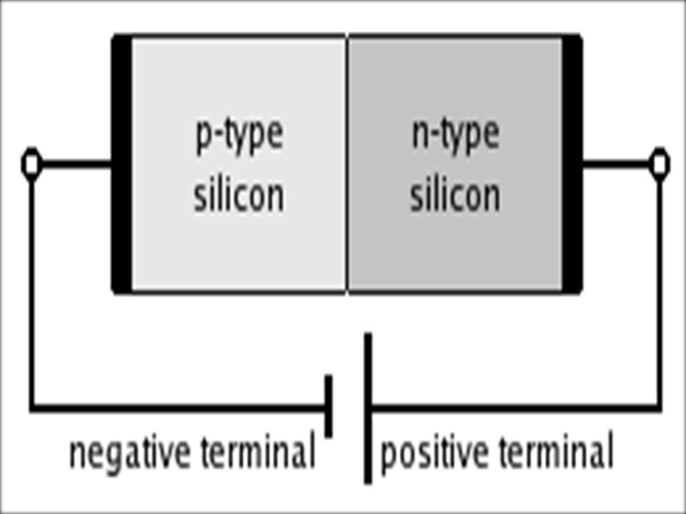
Forward bias the p-type is connected with the positive terminal and the n-type is connected with the negative terminal the holes in the P-type region and the electrons in the N-type region are pushed toward the junction. This reduces the width of the depletion zone.

21
Reverse bias the p-type is connected with the negative terminal and the n-type is connected with the positive terminal the voltage at the cathode is higher than that at the anode. So, no current will flow the holes in the P-type material are pulled away from the junction, causing the width of the depletion zone to increase. Likewise, the electrons in the n-type material will also be pulled away from the junction.

23
The reverse saturation current Threshold voltage Break down voltage

24
What is a "thin film" ?What is a "thin film" ? thin = less than about one micron ( 10,000 Angstroms, 1000 nm) thin = less than about one micron ( 10,000 Angstroms, 1000 nm) film = crystalline or amorphous layer of material on a substrate film = crystalline or amorphous layer of material on a substrate
 thin = less than about one micron ( 10,000 Angstroms, 1000 nm) film = crystalline or amorphous layer of material on a substrate film = crystalline or amorphous layer of material on a substrate.")
25
Thin films are crystalline or amorphous layers, typically 1 nm – 10 µm thick, deposited on a substrate.

26
Classification of Thin Films single crystals Polycrystalline amorphous

27
Properties of Thin Films not fully dense under stress quasi - two dimensional (very thin films)
")
28
gla ss Substrate(tr ansparent conducting oxide ) Thin film
 Thin film")
29
thin film deposition Chemical Vapor Deposition Physical Vapor Deposition Electrodeposition Langmuir-Blodgett

30
Chemical Vapor Deposition process used to produce high-purity, high- performance solid materials Reactive gases interact with substrate Used to deposit Si and dielectrics Type of CVD Atmospheric pressure – APCVD Low pressure – LPCVD Plasma enhanced – PECVD High density plasma - HDPCVD

31
Chemical Vapor Deposition Involves one or more gas phase species which react on a solid surface (substrate) to deposit a solid film. the reaction is initiated by heating the substrate. Other mechanisms of supplying the activation energy necessary to initiate reactions include: laser CVD, photo CVD, and plasma enhanced CVD.

32
Physical Vapor Deposition There are two type of PVD :- evaporation Sputtering Very few chemical reactions deposits almost any material Always performed in vacuum. Vacuum increases mean free path of ions or atoms Vacuum is typically less than 10 –4 Torr

33
A thermal evaporator uses an electric resistance heater to melt the material and raise its vapor pressure to a useful range. This is done in a high vacuum, both to allow the vapor to reach the substrate without reacting with or scattering against other gas-phase atoms in the chamber, and reduce the incorporation of impurities from the residual gas in the vacuum chamber.

34
Sputtering (sputtering mean a process which atoms are ejected from a solid target material due to bombardment of the target by energetic particles).This way is one of the most flexible deposition techniques. It is especially useful for compounds or mixtures, where different components would otherwise tend to evaporate at different rates. Uses a plasma (usually a noble gas, such as argon) to knock material from a "target" a few atoms at a time. The target can be kept at a relatively low temperature, since the process is not one of evaporation. Sputtering widely used in the optical media. The manufacturing of all formats of CD, DVD, and BD are basically done with the help of this technique. It is a fast technique and also it provides a good thickness control
 to knock material from a target a few atoms at a time. The target can be kept at a relatively low temperature, since the process is not one of evaporation. Sputtering widely used in the optical media. The manufacturing of all formats of CD, DVD, and BD are basically done with the help of this technique. It is a fast technique and also it provides a good thickness control.")
35
Applications microelectronics - electrical conductors, electrical barriers, diffusion barriers. magnetic sensors - gas sensors optics - anti-reflection coatings solar cell fabrication photodiodes switching devices

36
Uses microelectronic devices telecommunication devices wear resistant coatings optical coatings (windows,solar cells) Sensors catalysts
 Sensors catalysts")
37
Reference Karl W. Böer, “Survey of Semiconductor Physics Volume II: Barriers, Junctions, Surfaces, and Devices”, Springer,617-619 (1992). Always Learning, “Electronic Devices and Circuits”, Pearson Education India,26-27 (2008). Preeti Maheshwari, “Electronic Components and Processes”, New Age International,25( 2006). R.S.Sedha, “A Textbook of Electronic Circuits”, S. Chand, 32-45(2008).
. Always Learning, Electronic Devices and Circuits , Pearson Education India,26-27 (2008). Preeti Maheshwari, Electronic Components and Processes , New Age International,25( 2006). R.S.Sedha, A Textbook of Electronic Circuits , S. Chand, 32-45(2008)..")
38
S. Mani Naidu, Naidu S. Mani,” Applied Physics”, Pearson Education India,38-45( 2009). Simone Raoux, Matthias Wuttig, “Phase Change Materials: Science and Applications”, Springer, 102(2010). Masanori Okuyama, Yoshihiro Ishibashi, “Ferroelectric Thin Films: Basic Properties and Device Physics for Memory Applications”, Springer, (2005). Y.Paulean,“Chemical Physics of Thin Film Deposition Processes for Micro- And Nano-Technologies”, Springer,vii-4( 2002).
. Masanori Okuyama, Yoshihiro Ishibashi, Ferroelectric Thin Films: Basic Properties and Device Physics for Memory Applications , Springer, (2005). Y.Paulean, Chemical Physics of Thin Film Deposition Processes for Micro- And Nano-Technologies , Springer,vii-4( 2002)..")
41
any solid object in which an orderly three- dimensional arrangement of the atoms, ions, or molecules is repeated throughout the entire volume Single crystal

42
materials are solids that are composed of many crystallites of varying size and orientation. The variation in direction can be random (called random texture) or directed. all common metals and many ceramics are polycrystalline Polycryst alline
 or directed. all common metals and many ceramics are polycrystalline Polycryst alline.")
43
non- crystalline solid is a solid that lacks the long- range order characte ristic of a crystal. amorp hous

Similar presentations


>")


>")


 Also:n 0 p 0 = n.>")


