Download presentation
Presentation is loading. Please wait.

1
Zhongxing Telecom Pakistan (Pvt.) Ltd
BACKGROUND ALARM SYSTEM OF ZXJ10 Training Center Zhongxing Telecom Pakistan (Pvt.) Ltd
 Ltd.")
2
NEED OF ALARM SYSTEM Once the Switching System Has Been Established and Put Into Operation, It Must Be Supervised So That Its Real Time Maintenance and Repair Can Be Done. And All This Is Implemented by the Alarm Interface

3
Structure of the alarming system

4
The functions of the alarming system
The main functions of the foreground alarming system of the switch The main functions of the alarming system at the server end The main functions of the client alarming system

5
Foreground alarming system
Timely reflects the running state of the rack; Monitors the states of the slots on the rack and timely reports the problems, if any, to the background alarming system; Processes the information sent by the environment monitoring board and sends the processing result to the background alarming system; Executes background man-machine interface commands and returns the execution results.

6
Alarming system at the Server End(1/2)
Stores the history alarms; Stores the notification information; Stores the masking information; Stores the commissioning information; Stores the environment information;

7
Alarming system at the Server End(2/2)
Stores the configuration information; Guarantees the synchronization between the switch foreground and the background client and forwards the messages from MP to the clients in time; Processes various configuration commands from the clients; Controls the alarm panel (optional).
.")
8
Client alarming system(1/2)
Displays the latest alarm information in real time; Prints the latest alarm information instantly; Inquires and prints the current alarm contents; Inquires and prints the history alarm contents; Inquires and prints the notification information;

9
Client alarming system(2/2)
Sets and clears the alarm masking; Sets the environmental alarm conditions and starts and closes the environmental alarm; Displays the rack diagram and the information about the nodes at different levels; Displays the man-machine command operations and the results; Controls the alarm panel (optional).
.")
10
Functions of background alarm system
Mask alarm or de-mask alarm, setting conditions for environment alarm Real time display and instant printing of the latest alarm information Inquiry of present alarms and historic alarms and the content of notices Instant printing of the results of all kinds of inquiries Dynamic display of rack figure Inquiry of the output of the interface commands. Queries the interface command execution result

11
SOME BASIC TERMS(1/2) ALARMS The alarms are usually failures that occur during the running of the switching system.They usually lasts for certain period of time and does not recover until the failure disappears. The operators can inquire according to the actual conditions. There are four levels of alarms: major(1), serious(2), important(3) and average(4).
, serious(2), important(3) and average(4).")
12
NOTICE SOME BASIC TERMS(2/2)
They are some prompts during the running of the running of the switch. They function to keep the operators informed with the running state of each part of the switch. They are not in levels and do not need any maintenance.

13
ALARM OFFICE CONFIGURATION(1/4)
After the alarm system is installed, the configuration of the alarm office should be conducted after that. This configuration program requires input of the Area code,Office number, The modules in the office, The number of each module,The rack number .The results of office configuration are saved in the database of the server. The new configuration is valid only after the program in the alarm server is restarted.

14
ALARM OFFICE CONFIGURATION(2/4)
Now once the office has been configured System Maintenance Alarm Now the following window will appear.

17
PAGE LAYOUTS OF DIFFERENT NODES(1/4)
PAGE LAYOUT OF THE OFFICE NODE Information Overview Information Inquiry Management of Database

22
COLOURS FOR ALARMS Red level 1 alarm. Blue level 2 alarm.
Yellow level 3 alarm. White level 4 alarm. Kelly standby state. Green active state. Dark gray mask state. Gray out-of-control state.

24
INFORMATION INQUIRY It enables the operator to inquire present alarms, historic alarms, and notices. The inquiry of alarms can be conducted according to the alarm level and alarm code, while the inquiry of the notices can be conducted according to notice code.

25
To inquire the existing alarm of the present exchange
CURRENT ALARM INQUIRY To inquire the existing alarm of the present exchange Select corresponding node in the office tree in the left part of the window. When an office node is selected, the information to be inquired is the information of all modules under this office node. When a place node is selected, the information to be inquired is that of all modules under this place. When a module node is selected, the information to be inquired is that of this module.

28
HISTORIC ALARM INQUIRY
Historic alarm is an alarm that has happened before. The records of these alarms are saved in the database of the alarm server.

30
NOTICE INQUIRY The inquiry of notice information is similar to that of historic alarm, only that this inquiry must be conducted according to the notice code.

32
ALARM MASK AND MASK REMOVAL(1/2)
The alarm mask is divided into position mask and alarm code mask. The alarm mask is closely related to the module, the mask is set in the “alarm setting” page in the module node.

34
ALARM MASK AND MASK REMOVAL(2/2)
The “masked alarm information presented during inquiry” in mask display setting box at the bottom of the interface enables the operator to choose to see the alarm mask information while the inquiry is conducted. When this option is selected, the masked alarm will display with the mark **.

37
CALL RESTRICTION MANAGEMENT(1/2)
When CPU occupation rate or resource occupation rate is too high, the switch does not present normal running. In order to avoid this, a valve value for the resource occupation rate can be set in the page “call restriction management” to restrict calls

38
CALL RESTRICTION MANAGEMENT(2/2)
The vertical coordinates of the table indicates CPU occupation rate (%), the value ranging from 0 ~100. There are three valve values. The horizontal coordinates of the table indicates resource occupation (%), the value ranging between 0~100. There are three valve values. Both CPU occupation rate and resource occupation rate are divided into four sections. These two values combined to form five levels of call limitation: 0, 1, 2, 3, and 4(refer to call restriction table). BHCA has four valve values and are divided into five sections, corresponding to five levels of call limitation.
, the value ranging from 0 ~100. There are three valve values. The horizontal coordinates of the table indicates resource occupation (%), the value ranging between 0~100. There are three valve values. Both CPU occupation rate and resource occupation rate are divided into four sections. These two values combined to form five levels of call limitation: 0, 1, 2, 3, and 4(refer to call restriction table). BHCA has four valve values and are divided into five sections, corresponding to five levels of call limitation.")
40
DATABASE MANAGMENT “Management of database” can help inquire the size, the state, the records of the designated time period, and the earliest record time of the database. It can also be used to delete the records of the designated time period.

42
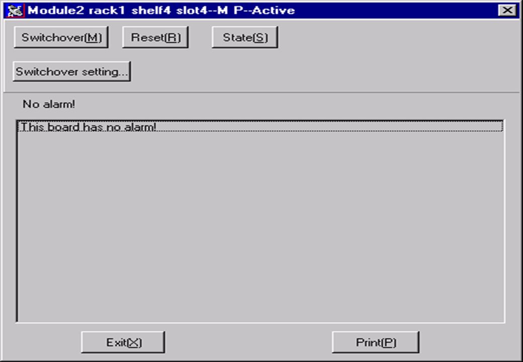
MAN MACHINE COMMANDS(1/2)
Each board position of the “rack state diagram” is in fact a command button. When the state is not out-of-control, operations can be conducted on it, i.e. certain man-machine commands can be executed. The man-machine commands have different levels. If the current user level is lower than the required level, the current operation can not be executed.

43
MAN MACHINE COMMANDS(2/2)
The man-machine commands are divided into the following types according to their functions .Some of them are: Functional information inquiry Switchover between active and standby state Resetting Inquiry of state Switchover settings

Similar presentations