Download presentation
Presentation is loading. Please wait.

1
PLEASE USE THE ENTER KEY RIGHT CLICK ON THE MOUSE TO ADVANCE
OR RIGHT CLICK ON THE MOUSE TO ADVANCE

2
PLEASE FIRST READ LESSON #6 –
Starting and Setting Up Drawings and Opening Existing Drawings Prior to viewing this presentation.

3
What are the steps to create a
NEW DRAWING ?

4
CREATING A NEW DRAWING AS A TEMPLATE OR
STANDARD DRAWING FOR USE IN LATER ASSIGNMENTS When Autocad is first opened a drawing is displayed called Drawing1.dwg This drawing contains pre-set settings which need to be changed. The changes will provide the tools for a better creative CAD drawing. These changes will improve your speed, accuracy, efficiency and grade. Most of the setting changes will take place within DIALOG BOXES. The Dialog Boxes will be quickly accessed through the Format Pull-Down Menu.

5
Lets first change the drawing name.
STEP 1 SAVE YOUR DRAWING Lets first change the drawing name. Select from the Menu Bar File, Save As

6
NEVER USE THE SAME NAME TWICE
The Save Drawing As DIALOG BOX appears displaying your student directory. Enter the file name using your initials followed by the drawing name as illustrated. NEVER USE THE SAME NAME TWICE

7
The new drawing name will appear above

8
WITHIN THE DIALOG BOXES Select Format from the Menu Bar
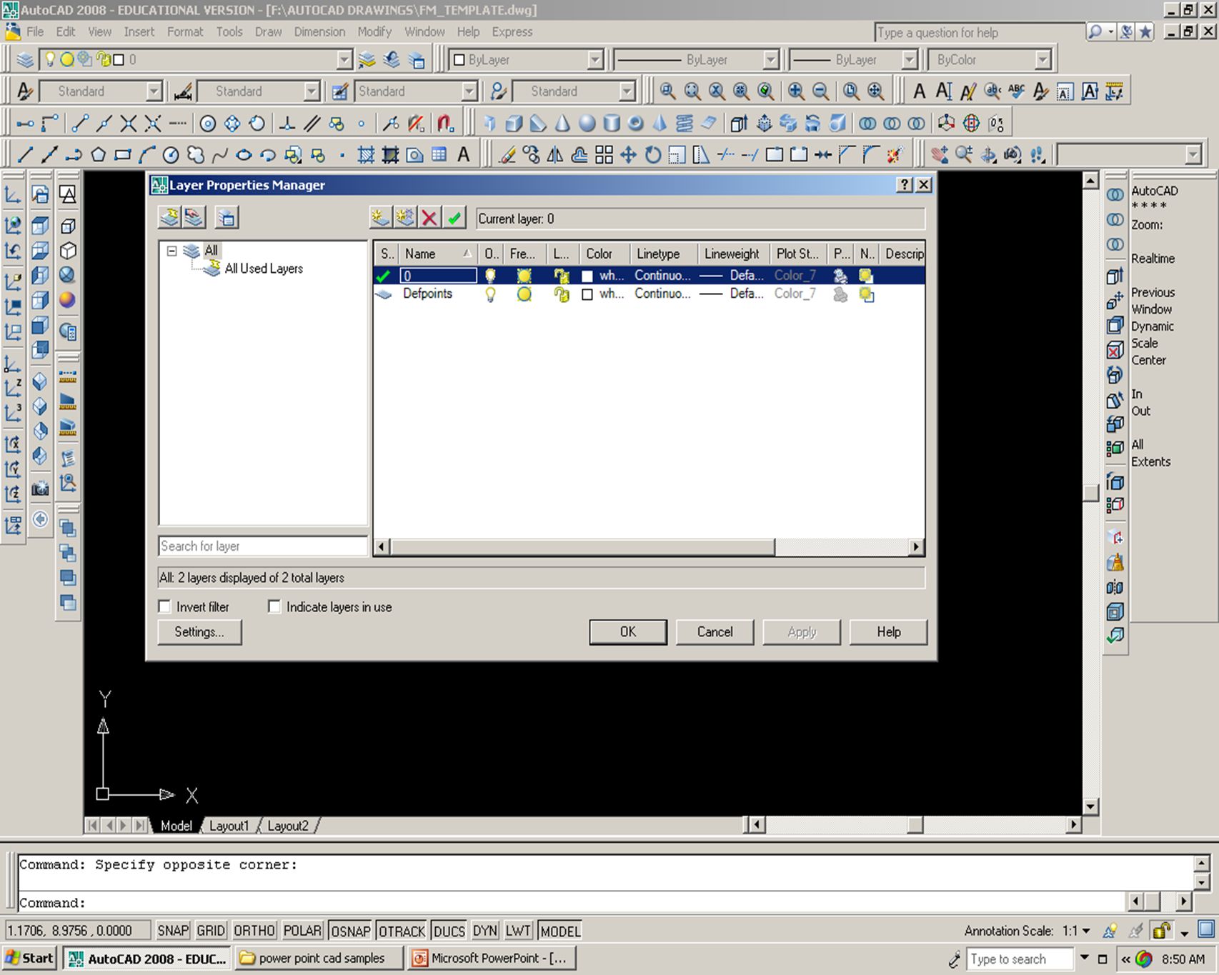
STEP 2 MAKING CHANGES WITHIN THE DIALOG BOXES Select Format from the Menu Bar The following DIALOG boxes will be changed Layer…, Linetype…, Text Style…, Dimension Style…, Point Style…,Units…, Drawing Limits… Lets first examine the content of each Dialog Box Prior to making changes.

15
The Layer Properties Manager controls the components listed within Layers. As you can see a minimum number of layers exist. Layers will later be explained in greater detail in another presentation.

16
New Layer Icon. Lets create another layer by selecting the New Layer Icon. Call the layer DIMENSIONS and make its color Red

17
Using LAYERS is imperative while working in Autocad
New Layer Using LAYERS is imperative while working in Autocad

18
Lets add addition Linetypes by selecting Load…
LOADING LINETYPES Lets add addition Linetypes by selecting Load…

19
A dialog box appears giving you the ability to load line types.
Proceed to load in the following line types: Center and Hidden

20
Slide shows several Linetypes loaded.

21
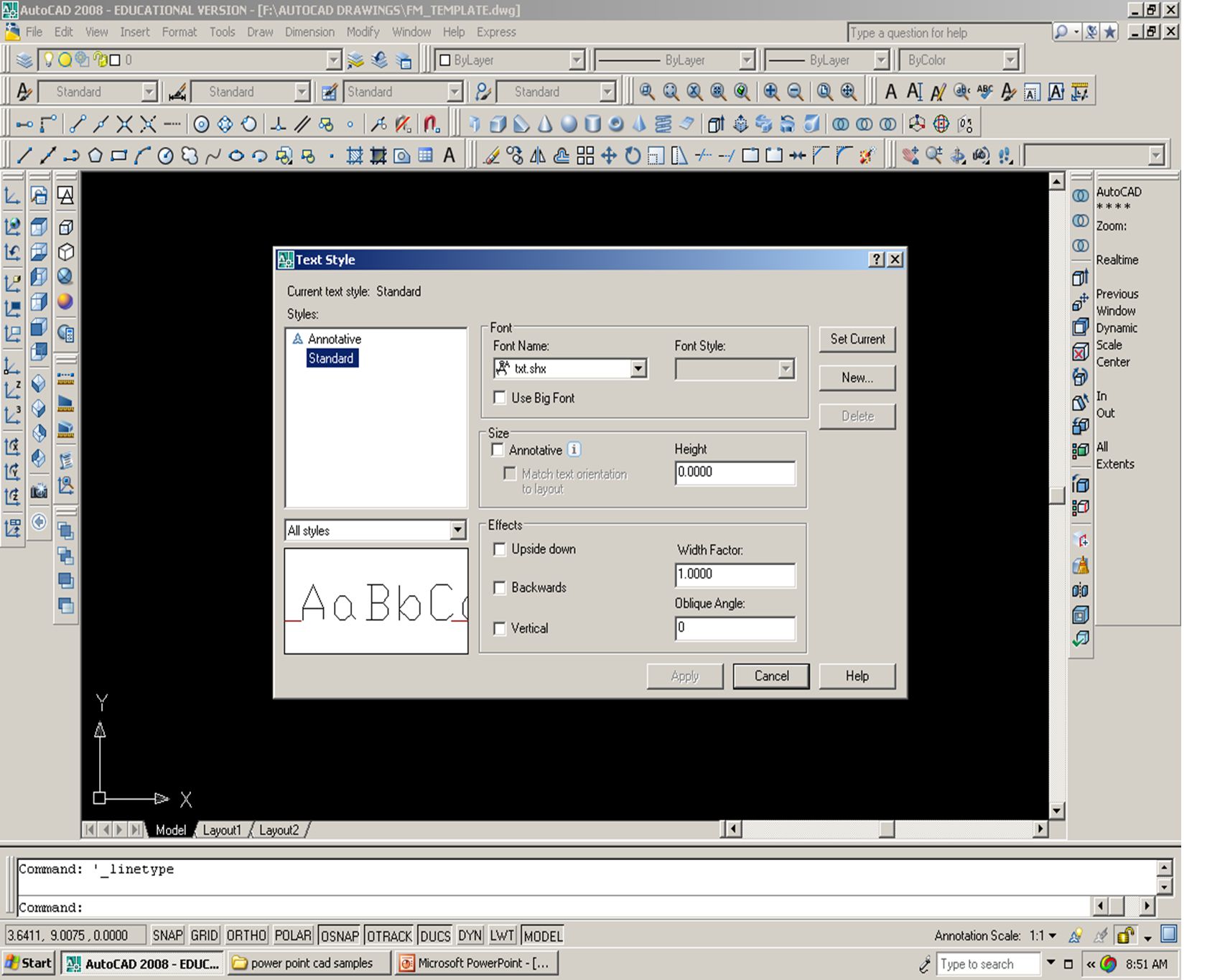
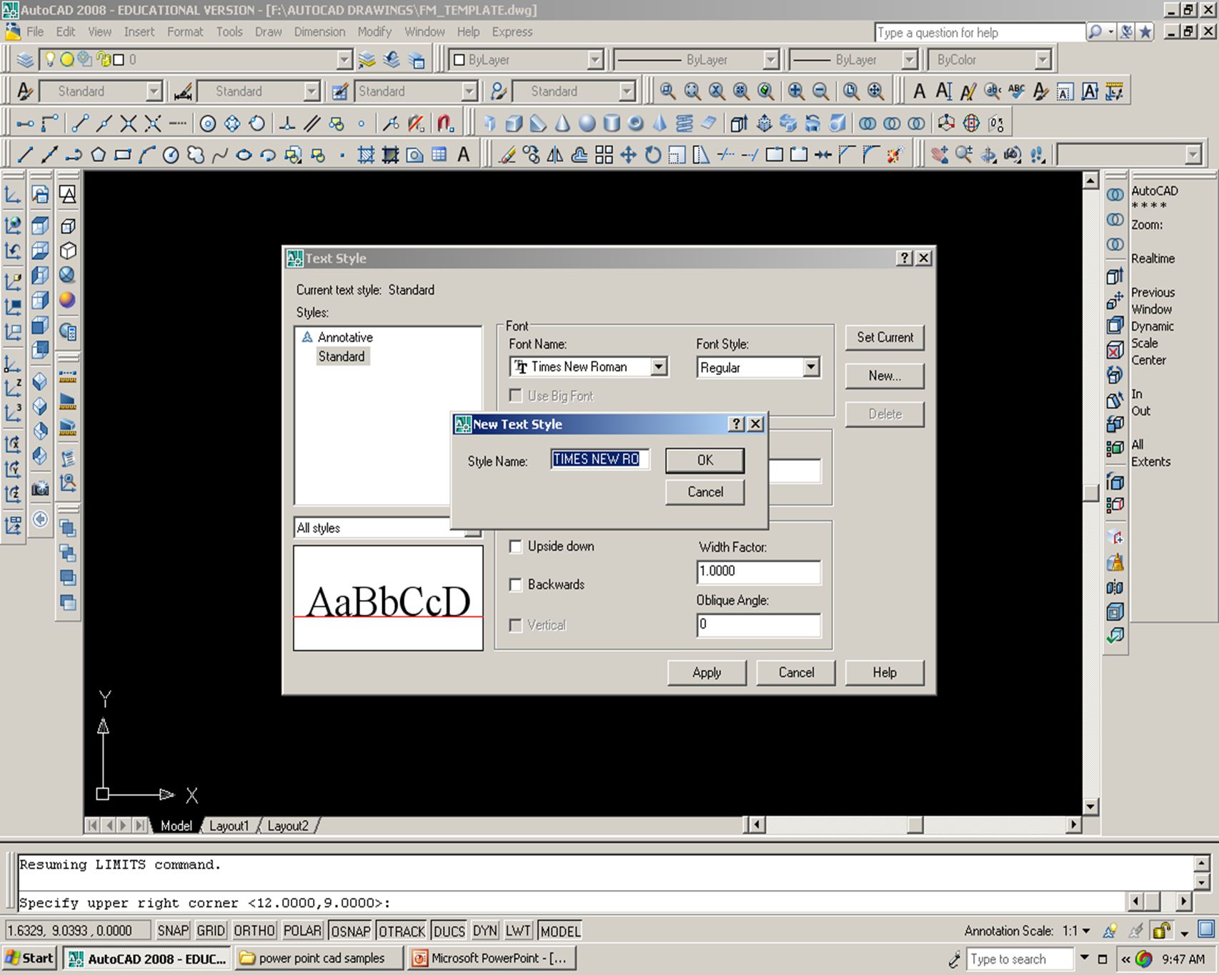
The Text Style Dialog Box contains the Standard Style Font.
DO-NOT CHANGE THE STYLE OF THIS FONT Add additional Fonts by selecting the font name choice under Font and then select the New….. button. In the next Dialog Box give the name of the new font style using the same name of the font selected.

23
The new style Times New Roman has been added to the list.

24
The Dimension Style Manager
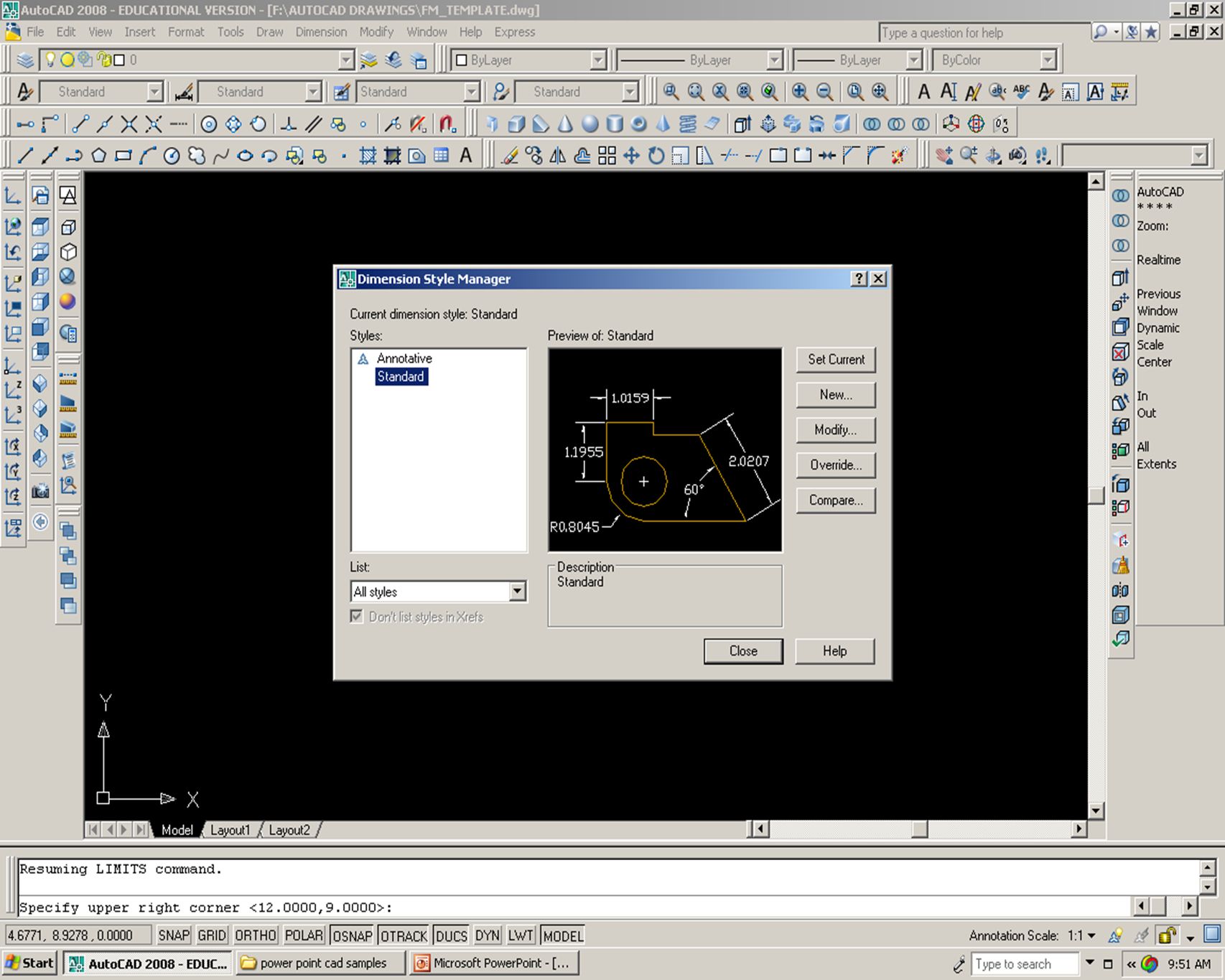
The Dimension Style Manager controls the look of dimensions as they are placed on a drawing. Using the Modify... Pick Box will display a Dialog Box for editing basic settings.

25
This Dialog Box will be explained in another presentation.

26
Point Styles are used with other commands such as the Divide Command.
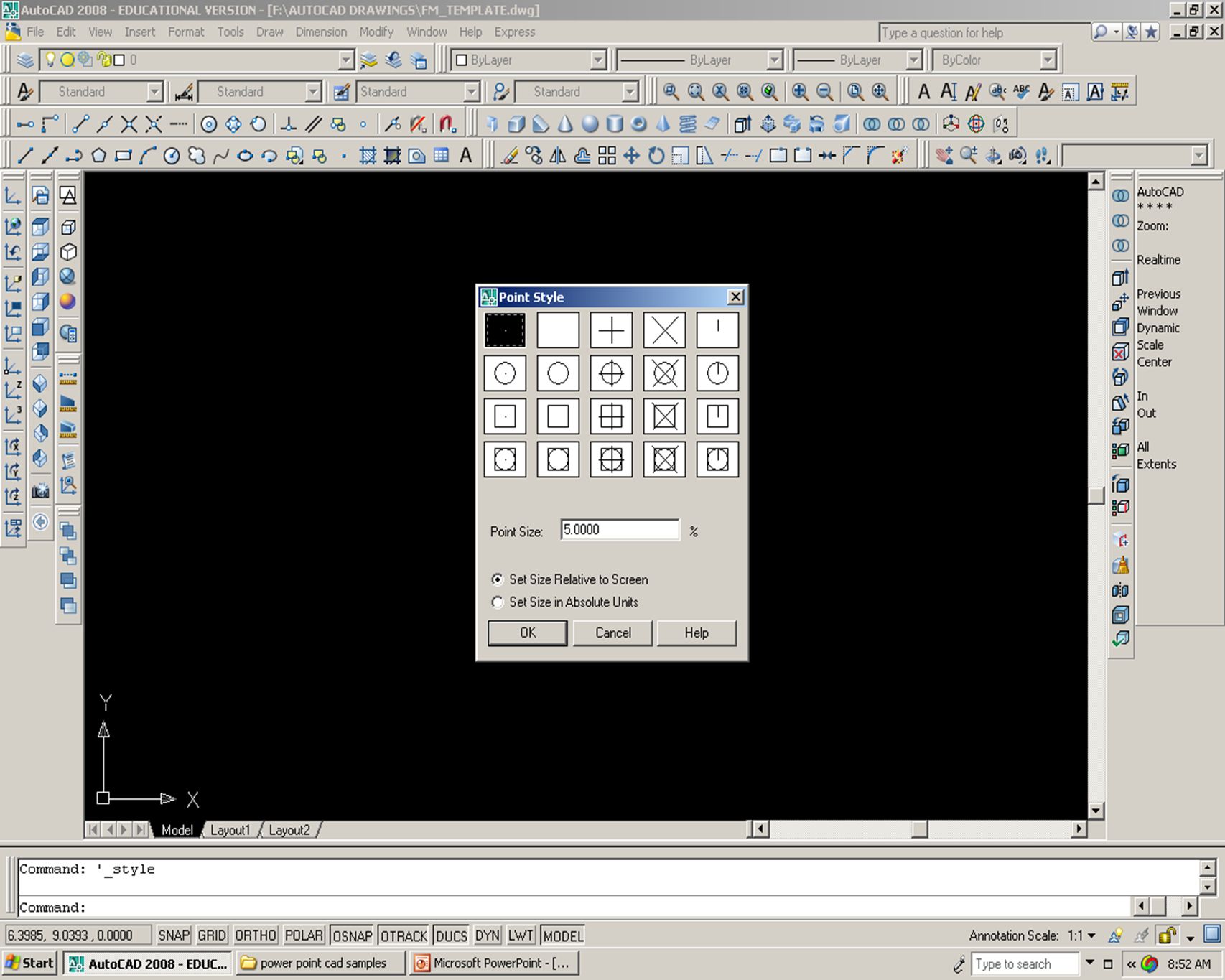
POINT STYLE DIALOG BOX Point Styles are used with other commands such as the Divide Command. Change the point style and size as show. Be sure to select the Radial Button Set Size IN Absolute Units

27
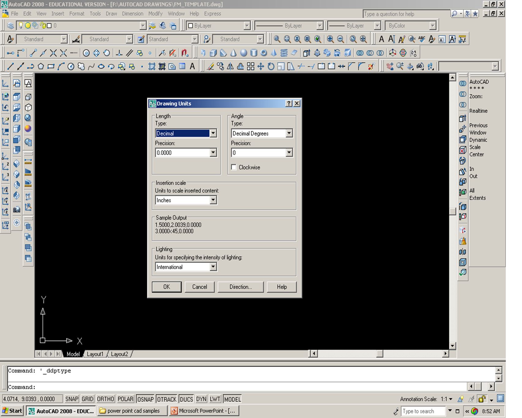
Depending on the type of drawing you are working (Mechanical or Architectural ) The Drawing Units may need to be changed.
 The Drawing Units may need to be changed.")
28
The drawing units may be changed to any of (5)choices. They are:
DECIMAL, ARCHITECTURAL, ENGINEERING, FRACTURAL, SCIENTIFIC

29
CHANGING THE DRAWING LIMITS
Drawing Limits represents the sheet size or paper size of your drawing. This is the area in which a helping grid will appear. LOOK AT THE COMMAND LINE AREA. You will see that after selecting Drawing Limits from the Format pull-down Menu Bar the system asks you for the location of the lower left corner of the paper edge. The value displayed <0.000, 0.000> must be selected by depressing the Enter key.

30
A SECOND QUESTION IS PRESENTED TO THE OPERATOR
Specify upper right corner the value <12.000, 9.000> is the pre-set size and can be changed to any sheet size paper you wish. Coordinates of the sheet are typed in by entering the X value & then the Y value of the upper right corner. To change the paper to a large C size sheet type 22, 17 This number represents a sheet size of 22 inches in length along the X axis and 17 inches in height along the Y axis. To confirm the limits have been changed simply move the Cursor to the upper right corner of the drawing space.

31
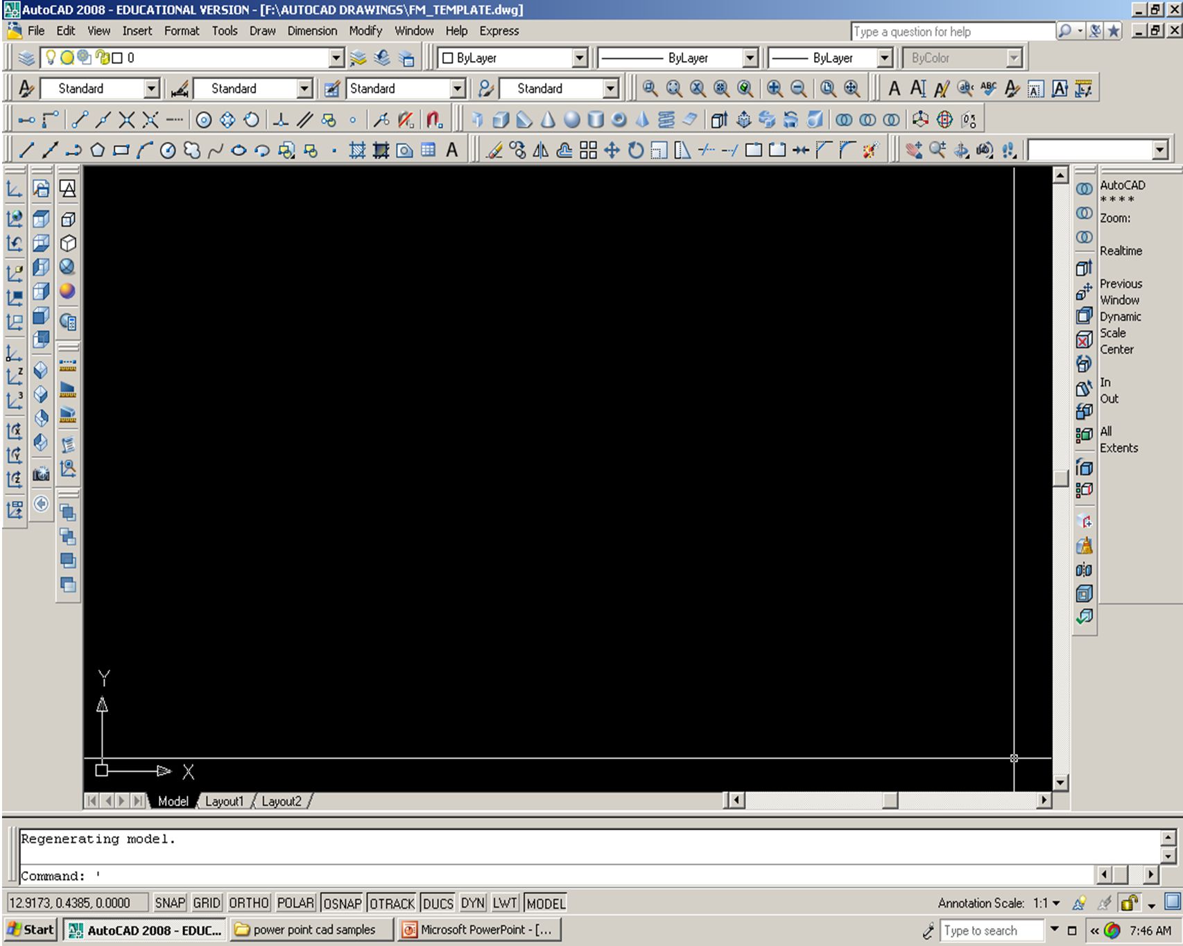
Move the Cursor to the upper right corner
The new value of the upper right corner of the Drawing Limits has been entered. Move the Cursor to the upper right corner to confirm the change.

32
Confirming the upper right corner coordinates of the drawing limit is made easy by first displaying the Grid pattern (F7) and having the Snap Mode (F9) turned ON. Move the Cursor to the upper right corner and read the coordinates in the Coords Display ,17.000,0.000 The numbers indicate the coordinates of the upper right corner of the paper sheet working area and confirms the changes made to the Drawing Limit. The new value of the upper right corner of the Drawing Limits has been entered.

33
THE FINAL DRAWING SETTING CHANGES
Will be made by selecting the icon from the Object Snap Toolbar called Osnap Settings…. The Drafting Settings Dialog Box will appear and changes to the sizes of the helping features known as GRID and SNAP can be made. Selecting the Object Snap Tab will enable you to pick OSNAP (Object Snap) settings which will enable you to select any point on objects such as lines and circles Accurately with ease of picking the point. OSNAP WILL BE EXPLAINED IN GREATER DETAIL IN A LATER PRESENTATION.
 settings which will enable you to select. any point on objects such as lines and circles. Accurately with ease of picking the point. OSNAP WILL BE EXPLAINED IN GREATER DETAIL. IN A LATER PRESENTATION.")
34
Change the size of the helping GRID and SNAP to the same value.
The Drafting Settings Dialog Box can also be opened by simply typing DS on the keyboard Change the size of the helping GRID and SNAP to the same value.

35
Select the Object Snap Tab and check off the following choices:
ENDPOINT MIDPOINT CENTER INTERSECTION PERPENDICULAR Notice the symbols representing the Object Snap Modes

36
We have now completed SETTING UP a Standard Drawing or Template for use on other CAD Assignments.
REVIEW THIS PRESENTATION AND FOLLOW ITS INSTRUCTIONS IN CLASS TO CREATE YOUR OWN TEMPLATE.

Similar presentations