Download presentation
Presentation is loading. Please wait.

1
Drafting – Product Design & Architecture
Perspective Pictorial

2
Perspective Drawings A perspective drawing offers the most realistic three-dimensional view of all the pictorial methods, because it portrays the object in a manner that is most similar to how the human eye perceives the visual world.

3
Perspective Drawings 1-Point 2-Point 3-Point

4
One-Point Perspective
Perspective Sketches Introduction to Engineering DesignTM Unit 1 – Lesson 1.2 – Intro to Technical Sketching One-Point Perspective The one-point perspective is relatively simple to make, but is somewhat awkward in appearance when compared to other types of pictorials. A horizontal line, representing the horizon, is drawn across the upper portion of the paper. One vanishing point is identified somewhere on the horizon line. Students should understand the concept of setting up the horizon line and vanishing point. Project Lead The Way, Inc. Copyright 2007

5
One-Point Perspective
Perspective Sketches Introduction to Engineering DesignTM Unit 1 – Lesson 1.2 – Intro to Technical Sketching One-Point Perspective A horizontal line, representing the horizon, is drawn across the upper portion of the paper. One vanishing point is identified somewhere on the horizon line. A series of lines are drawn from distinctive points outlining the object being constructed. The end result looks like the next slide. It is not as important the proper location of horizon line or vanishing point, as long as they are located in the upper portion of the sheet which you are sketching on. The objective of this part of the lesson is that students understand what a perspective sketch is. Project Lead The Way, Inc. Copyright 2007

6
Perspective Sketches Introduction to Engineering DesignTM Unit 1 – Lesson 1.2 – Intro to Technical Sketching A detailed outline of how to set up a perspective sketch is demonstrated using two-point perspective. Project Lead The Way, Inc. Copyright 2007

7
Two-Point Perspective
Perspective Sketches Introduction to Engineering DesignTM Unit 1 – Lesson 1.2 – Intro to Technical Sketching Two-Point Perspective The two-point perspective is the most common perspective drawing. A step-by-step procedure will be explained for the perspective. Two-point is the most common method and one students will understand more. In the Activity that accompanies this PowerPoint, you may want students to do two-point for the final problem. Project Lead The Way, Inc. Copyright 2007

8
Two-Point Perspective
Perspective Sketches Introduction to Engineering DesignTM Unit 1 – Lesson 1.2 – Intro to Technical Sketching Two-Point Perspective A horizontal line, representing the horizon, is drawn across the upper portion of the paper. Two vanishing points are then identified, one on either end of the horizon line. The most common of the three perspective sketches. Project Lead The Way, Inc. Copyright 2007

9
Two-Point Perspective
2nd Method

10
Two-Point Perspective
A horizontal line, representing the horizon, is drawn across the upper portion of the paper. Two vanishing points are then identified, one on either end of the horizon line. A vertical construction line is drawn, which represents the overall height of the object. Two points are marked on this line, which represent a top and bottom corner of “the box” within which the object will be sketched.

11
Two-Point Perspective
2nd Method

12
Two-Point Perspective
Two construction lines are drawn from each point to the vanishing points on the horizon line.

13
Two-Point Perspective
2nd Method

14
Two-Point Perspective
4. Points and vertical construction lines are drawn to represent the overall width and depth of the object. Their locations must be estimated to make the overall dimensions of “the box” appear proportional. Once properly located, construction lines are drawn from the top points to the vanishing points on the horizon line.

15
Two-Point Perspective
2nd Method

16
Two-Point Perspective
Points and construction lines are used to identify the corners of the object that occur on the visible surfaces of “the box.”

17
Two-Point Perspective
2nd Method

18
Two-Point Perspective
6. Depending on the complexity of the part, it may be advantageous to trace over the visible edges with object lines before the drawing becomes cluttered with points and construction lines.

19
Two-Point Perspective
2nd Method

20
Two-Point Perspective
Points and construction lines are used to identify the corners of the object that occur inside “the box.”

21
Two-Point Perspective
2nd Method

22
Two-Point Perspective
Object lines are then drawn over the construction lines to delineate the visible edges of the part.

23
Two-Point Perspective
2nd Method

24
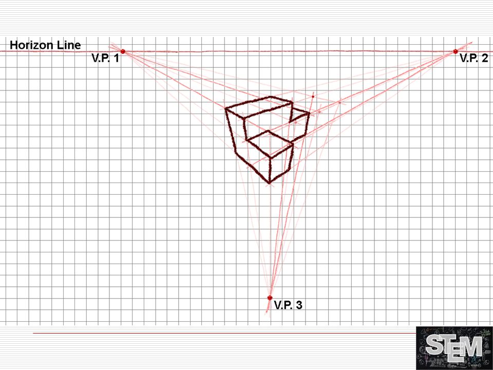
Three-Point Perspective
The three-point perspective gives the viewer either a worm’s eye, or bird’s eye view of an object.

25
Three-Point Perspective
This is set up similar to the two-point perspective; however, a third vanishing point is identified near the bottom of the construction line. The end result looks like the next slide.

Similar presentations


>")