Download presentation
Presentation is loading. Please wait.

1
AMPTEC 601ES Explosive Safety DMM– Operator Training

2
AMPTEC 601ES Explosive Safety Safety DMM – Startup Check Out Procedure
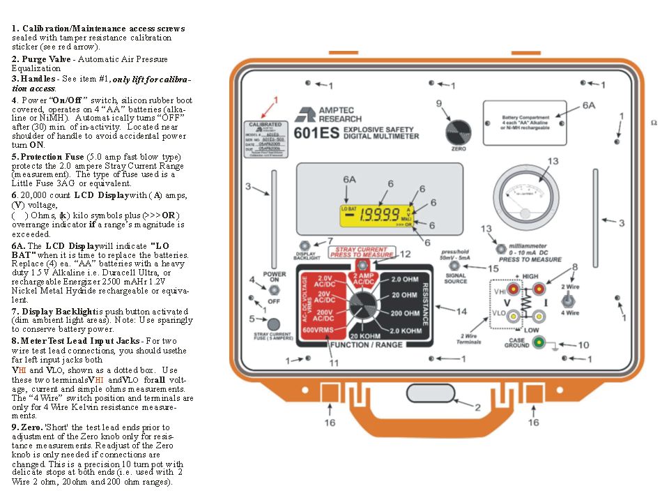
The first item to examine is to check the calibration sticker due date for the AMPTEC 601ES Explosive Safety DMM. If the due date is still valid and not expired, it Is ready to begin the safety check procedure. If the calibration due date is expired then contact your calibration laboratory or AMPTEC RESEARCH. A tamper resistant calibration sticker is usually located around the perimeter area to the AMPTEC 601ES DMM covering one of the calibration access screws.

3
AMPTEC 601ES Explosive Safety Safety DMM – Startup Check Out Procedure
Step 1: Procedure for turning on the 601ES DMM – Using main operating power switch.

4
Step 2: Observe the 601ES DMM display after unit is “powered up”
Step 2: Observe the 601ES DMM display after unit is “powered up”. There should be no low battery (“LO BAT”) indicator present in the LCD display. ( see red circle area below) The “LO BAT” display means it is time to replace the unit’s “AA” batterries. ( shown without backlight) Since no “LO BAT” is displayed means, it means the unit’s batterries are OK. ( display shown with backlight lit mode ) The 601ES DMM is capable of indicating : “A” for amperes, “V” for voltage, , “k” for Kilo, “Ω ” for ohms. When the display indicates “>>> OR” or Overrange mode – it means possible “open circuit connection” or a higher range selection is required.
 indicator present in the LCD display. ( see red circle area below) The LO BAT display means it is. time to replace the unit’s AA batterries. ( shown without backlight) Since no LO BAT is displayed means, it means the unit’s batterries are OK. ( display shown with backlight lit mode ) The 601ES DMM is capable of indicating : A for amperes, V for voltage, , k for Kilo, Ω for ohms. When the display indicates >>> OR or Overrange mode – it means possible open circuit connection or a higher range selection is required.")
5
Step 3: Place the unit in “2 wire” measurement mode to begin the self check. (make sure that the 2 wire / 4 wire switch is in the the “up” position).
..")
6
Step 4: The next set of steps envolves checking (by viewing the analog milliammeter) each range and function to see that less than A ( or 5 mA) is ever output from any FUNCTION or selected range, into the unit’s onboard analog milliammeter. 2 sections of the AMPTEC 601ES DMM are used for this process. The FUNCTION/RANGE section and the on-board analog milliammeter.

7
Step 5: Select the 600 VRMS range (rotary switch in far counterclock position).
Then press and momentarily hold down the milliammeter “measure” switch. You should see virtually no movement in the analog milliammeter. (it’s scale is 0 to 10 mA fullscale).
.")
8
Step 6: Select the 200 VRMS range (rotary switch in 8 O’clock position).
Then press and hold the milliammeter “measure” switch. Again , you should see virtually no movement in the analog milliammeter. (it’s scale is 0 to 10 mA fullscale). The yellow line on range switch is shown for emphasis of position purposes.
. The yellow line on range switch is shown for emphasis of position purposes.")
9
Step 6: Select the 20 VRMS range (rotary switch in 10 O’clock position).
Then press and hold the milliammeter “measure” switch. Again, you should see virtually no movement in the analog milliammeter. (it’s scale is 0 to 10 mA fullscale). The yellow line on range switch is shown for emphasis of position purposes.
. The yellow line on range switch is shown for emphasis of position purposes.")
10
Step 7: Select the 2.0 VRMS range (rotary switch in ~11 O’clock position).
Then press and hold the milliammeter “measure” switch. Again, you should see virtually no movement in the analog milliammeter. The yellow line on range switch is shown for emphasis of position purposes.

11
Step 8: Select the 2.0 AMP AC/DC range (rotary switch in 12 O’clock position).
This step requires simultaneously pressing and holding down 2 buttons. *Press and hold the 2.0 AMP button ( see red arrow below) while you also press and hold the milliammeter “measure” switch. Again, you should see virtually no movement in the analog milliammeter.
 while you also. press and hold the milliammeter measure switch. Again, you should see. virtually no movement in the analog milliammeter.")
12
Step 9: Select the 2.0 OHM range (rotary switch in the 1 O’clock position).
Press and momentarily hold down the milliammeter “measure” switch. You should see the analog milliammeter needle deflect to to midscale or the 5 mA (verticle needle position is “OK” – the milliammeter scale is 0 to 10 mA fullscale). You should not see 5 ½ milliamperes, avoid paralax viewing error of the milliammeter by taking reading straight over the milliammeter - use one eye to view. ( 8 mA is the failsafe current level).
. You should not see 5 ½ milliamperes, avoid paralax viewing error of the milliammeter by taking reading straight over the milliammeter - use one eye to view. ( 8 mA is the failsafe current level).")
13
Step 10: Select the 20 OHM range (rotary switch in the 2 O’clock position).
Press and momentarily hold down the milliammeter “measure” switch. You should see the analog milliammeter needle deflect to to midscale or the 5 mA level. It should be the same as the 2.0 ohm current source level. A verticle needle position is “OK” – the milliammeter scale is 0 to 10 mA fullscale. Again, you should not see 5 ½ milliamperes, avoid paralax viewing error of the milliammeter by taking reading straight over the milliammeter - use one eye to view.

14
Step 11: Select the 200 OHM range (rotary switch in the ~3 O’clock position).
Press and momentarily hold down the milliammeter “measure” switch. You should see the analog milliammeter needle deflect to barely ~1 mA level. You should not see any level even close to 5 ½ milliamperes.

15
Step 12: Select the 2.0 KOHM range (rotary switch in the ~ 4 O’clock position).
Press and momentarily hold down the milliammeter “measure” switch. You should see the analog milliammeter needle deflect to barely any current or ~<1 mA level. You should not see any level even close to 5 ½ milliamperes.

16
Step 13: Select the 20 KOHM range (rotary switch in the 6 O’clock position).
Press and momentarily hold down the milliammeter “measure” switch. You should see the analog milliammeter needle indicate barely any current at all or ~<1 mA level. You should not see any level even close to 5 ½ milliamperes.

17
If the unit has successfully completed all the steps indicated it is ready to use.
This concludes the AMPTEC 601ES Explosive Safety DMM check out procedure.

Similar presentations


 by Herb Spenner.>")


>")


