Download presentation
Presentation is loading. Please wait.

1
Pvredator Gilad Lotan Physical Computing without Computers

2
Initial Concept

3
Aram Bartholl, random screen

4
Hong Kong Lantern Festival

5
Light Equinox at Chichen Itza, Mexico Light-Shadow snake (spring & fall)
")
6
Manhattanhenge Looking west along 42nd Street (Manhattan) at 8:23 p.m. on July 13, 2006. This photo shows the sun lined up with the center line of 42nd Street. It actually set slightly to the right. It set on the center line on July 12.42nd Street (Manhattan)
.")
7
Solistice & Equinox Solistice – twice a year when the sun is at its greatest distance from the equatorial plane Equinox – the sun directly above the equator Many cultures celebrate the winter and summer solstices (e.g. Christmas). Jewish cultures celebrate especially the equinoxes (Passover and Rosh Hashanah); in Japan, all four major season days are celebrated (Setsubun).PassoverRosh HashanahJapanSetsubun Winter solstice festivals (Yalda, Saturnalia, Karachun, Hanukkah, Kwanzaa and Ásatrúar).YaldaSaturnaliaKarachun HanukkahKwanzaaÁsatrúar In most cultures the solstices and equinoxes do not determine the start but the midpoint of the seasons.
. Jewish cultures celebrate especially the equinoxes (Passover and Rosh Hashanah); in Japan, all four major season days are celebrated (Setsubun).PassoverRosh HashanahJapanSetsubun Winter solstice festivals (Yalda, Saturnalia, Karachun, Hanukkah, Kwanzaa and Ásatrúar).YaldaSaturnaliaKarachun HanukkahKwanzaaÁsatrúar In most cultures the solstices and equinoxes do not determine the start but the midpoint of the seasons..")
8
Inspiration

9
Goals 1. Build an object that reacts according to the amounts of current it receives. 2. Raise awareness towards a more sustainable usage of energy

10
The Photovoltaic Effect sunlight photons free electrons from common silicon first discovered in the 18th century N-type, silicon w/phosphorus = more electrons, - P-type, silicon w/boron = less electrons, +

11
Drawbacks of PV cells The use of silicon crystals in the Photovoltaic cells makes it expensive. silicon crystals are currently assembled manually. Secondly, silicon purification is difficult and a lot of silicon is wasted. silicon cells require a cooling system: performance degrades at high temperatures. Research is underway for new fabrication techniques (like those used for microchips)
.")
12
Going Cheap

15
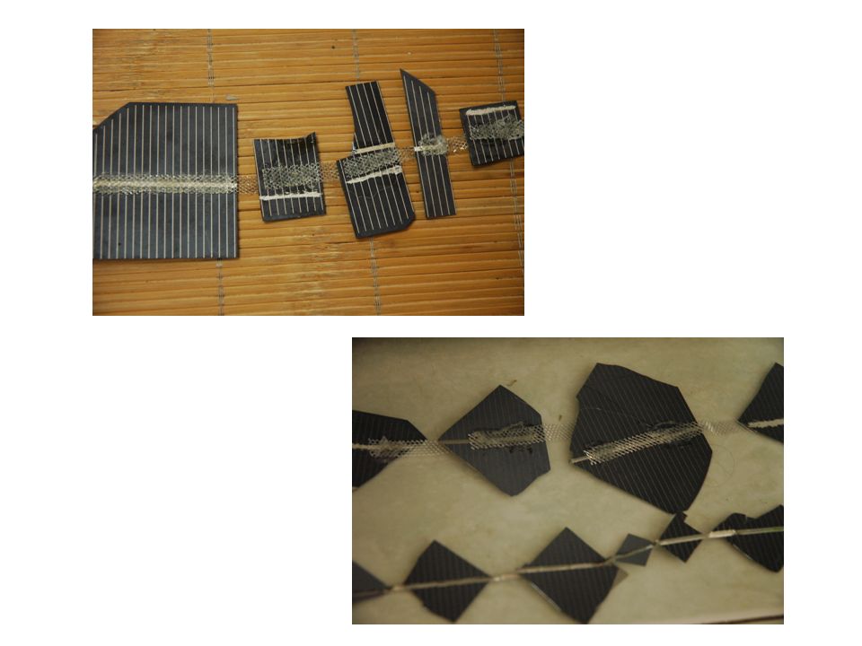
First try

17
The Miller Solar Engine

19
Future ?

20
1381 Solar Engine

21
Solar Engine

22
Solar Charger

23
Battery Charger

24
Using a Schottky Diode (1N5818) Introduction This almost trivial circuit may be used to charge a pair of AA or AAA sized rechargeable battery cells from sunlight. The circuit has been used to keep a Palm Pilot and walkman radio running perpetually. This is an unregulated charger, proper charging is achieved by placing the unit in the sun for a known amount of time, this time varies according to the battery type. Specifications Open Circuit Voltage: about 4.0V Closed Circuit Current: about 25ma (depending on the solar cell types) Charge Current: < 25ma (depending on the solar cell types) Charge Time AA cells: approximately 1 full day of direct sunlight Charge Time AAA cells: approximately 1/2 full day of sunlight Theory Each of the solar cells develops about 0.5 volts across itself when in full sunlight. The string of 8 solar cells puts out around 4V with no load. When the solar cells are connected to a battery, a current will flow and the battery will charge. Two versions of the circuit are shown in the schematic, the 8 solar cell panel with a diode is the recommended circuit. The diode prevents the battery from discharging through the cells at night and the 8th cell boosts the voltage up enough to compensate for the voltage drop across the diode. For an 8 solar cell panel, connect jumper J2 and disconnect J1. For a 7 solar cell panel, connect jumper J1 and eliminate SC8 and D1. Typically, the jumpers are not necessary, they are shown in the schematic to illustrate two ways to to build the circuit. For operation in cloudy weather, it may be useful to add one or two additional solar cells. It is a good idea to temporarily insert an amp (microamp) meter in series with the battery to measure the charging current in various light conditions. Since solar cells are current-limited devices, it is possible to use the circuit as-is to charge a single battery cell. If one cell is all you ever need to charge, five solar cells and a series diode will be sufficient for the task. Construction Lay out the solar cells to determine the size of the circuit board, allow for about 1/4" (1cm) of extra space around all four sides. Cut out one piece of perforated circuit board, one piece of solid PC board, and one piece of 1/8" clear plexiglass in this dimension. File all 3 pieces to achieve smooth edges. Drill 2 holes down the center line of the 3 pieces while holding them together allowing room for the screws to pass between the solar cells. Mount the two battery holders on the blank piece of circuit board with screws or silicon rubber glue. If the solar cells don't have wire connections, solder thin wires to the cells. Wire-wrap wire works well for this. Be careful not to overheat the solar cells, use a small soldering iron and only touch the cells for a few seconds at a time. The solar cells should be secured to the perf board with a drop of silicon rubber on the back side, or they can be held in place with the wires of the solar cell if you have the right kind of cell. Wire all of the cells in series, plus to minus, connect the two end wires to longer wires that go to the diode and battery holder. Typically, the positive connection is the metal on the back of the solar cell and the negative connection is the wire grid on the blue (front) side. Using a pair of 3/4 inch 6-32 machine screws and nuts or washers, make a sandwich of the 3 boards. Use the nuts or washers to make gaps between the board layers, it is important to prevent any contact between the solar cells and the plexiglass. The solar cells are very brittle and will break under compression. If you want to make the panel waterproof, cut 4 thin strips of solid circuit board or other plastic to fit around the sides of the sandwich. Glue these boards to the sides of the assembly with silicon rubber. Apply a small drop of glue to where the screws go through the plexiglass. Alignment None required unless you count pointing the panel at the sun. Use Insert two rechargeable cells in the battery holders, point the device at the sun, and let batteries charge for a few hours. Larger cells will need more charging time. The solar array should be placed in direct sun, it should not be shaded in any way. It might be a good idea to monitor the battery voltage during the first few charge cycles to get an idea of how much time is needed to reach a full charge. Do not let the rechargeable cells overheat. If the charger is left outdoors in the summer, the excess heat can cause the cells to leak out their electrolyte goo, ruining the cells. Operating the charger indoors behind a window may help to reduce the heat. Operation behind a window will cause a drop in the charge current, resulting in a longer charge time. This circuit works with rechargeable alkaline cells, NICD cells, or any other rechargeable that has a potential of 1.5V or lower per cell. If you build the 7 cell version (no diode), remove the cells at night to prevent discharge through the solar cells. It is advisable to connect a volt meter across the battery with a pair of alligator clips to observe the battery voltage as it charges. If you have a lot of batteries to charge, it is best to charge cells that are matched by brand. If possible, use cell pairs that start with a similar voltage, this allows both cells to finish charging at the same time. The NiCd Memory Effect Keep in mind that the so-called NiCd "memory effect" is largely an urban legend that started from a legitimate early 1960s Nasa experiment involving first generation NiCd cells charged and discharged within a very tight voltage range. The two biggest killers of modern NiCd cells are overheating during charging, and reverse voltages applied to the weak cells as the result of the complete discharge of multi-cell NiCd packs. Overheating can cause the loss of electrolyte, resulting in lowered cell capacity. Reverse voltage can cause conductive dendrites to grow in the cells making them self-discharge more rapidly. So called "memory effect" dischargers can actually cause the reverse voltage problem if used on multiple cell packs. The weakest cell in a pack will go to zero volts, then negative volts as the stronger cells discharge. Discharging can be a good way to insure that all cells are charged from the same starting point, just be sure to limit the minimum discharge voltage to around 1V per cell. Parts SC1-SC8 single photovoltaic solar cell,.5V, 20 to 50 ma output each in full sun D1 1x 1N5818 Schottky Diode Battery Holder 1x 2 cell AA or AAA battery holder Battery 2x AA or AAA NiCD or NiMH rechargeable cells Perf Board 1x for mounting solar cells PC board 1x solid piece for mounting battery holder Plexiglass 1x approx. 1/8" thick, cut to size misc hardware, wire
 Charge Current: < 25ma (depending on the solar cell types) Charge Time AA cells: approximately 1 full day of direct sunlight Charge Time AAA cells: approximately 1/2 full day of sunlight Theory Each of the solar cells develops about 0.5 volts across itself when in full sunlight. The string of 8 solar cells puts out around 4V with no load. When the solar cells are connected to a battery, a current will flow and the battery will charge. Two versions of the circuit are shown in the schematic, the 8 solar cell panel with a diode is the recommended circuit. The diode prevents the battery from discharging through the cells at night and the 8th cell boosts the voltage up enough to compensate for the voltage drop across the diode. For an 8 solar cell panel, connect jumper J2 and disconnect J1. For a 7 solar cell panel, connect jumper J1 and eliminate SC8 and D1. Typically, the jumpers are not necessary, they are shown in the schematic to illustrate two ways to to build the circuit. For operation in cloudy weather, it may be useful to add one or two additional solar cells. It is a good idea to temporarily insert an amp (microamp) meter in series with the battery to measure the charging current in various light conditions. Since solar cells are current-limited devices, it is possible to use the circuit as-is to charge a single battery cell. If one cell is all you ever need to charge, five solar cells and a series diode will be sufficient for the task. Construction Lay out the solar cells to determine the size of the circuit board, allow for about 1/4 (1cm) of extra space around all four sides. Cut out one piece of perforated circuit board, one piece of solid PC board, and one piece of 1/8 clear plexiglass in this dimension. File all 3 pieces to achieve smooth edges. Drill 2 holes down the center line of the 3 pieces while holding them together allowing room for the screws to pass between the solar cells. Mount the two battery holders on the blank piece of circuit board with screws or silicon rubber glue. If the solar cells don t have wire connections, solder thin wires to the cells. Wire-wrap wire works well for this. Be careful not to overheat the solar cells, use a small soldering iron and only touch the cells for a few seconds at a time. The solar cells should be secured to the perf board with a drop of silicon rubber on the back side, or they can be held in place with the wires of the solar cell if you have the right kind of cell. Wire all of the cells in series, plus to minus, connect the two end wires to longer wires that go to the diode and battery holder. Typically, the positive connection is the metal on the back of the solar cell and the negative connection is the wire grid on the blue (front) side. Using a pair of 3/4 inch 6-32 machine screws and nuts or washers, make a sandwich of the 3 boards. Use the nuts or washers to make gaps between the board layers, it is important to prevent any contact between the solar cells and the plexiglass. The solar cells are very brittle and will break under compression. If you want to make the panel waterproof, cut 4 thin strips of solid circuit board or other plastic to fit around the sides of the sandwich. Glue these boards to the sides of the assembly with silicon rubber. Apply a small drop of glue to where the screws go through the plexiglass. Alignment None required unless you count pointing the panel at the sun. Use Insert two rechargeable cells in the battery holders, point the device at the sun, and let batteries charge for a few hours. Larger cells will need more charging time. The solar array should be placed in direct sun, it should not be shaded in any way. It might be a good idea to monitor the battery voltage during the first few charge cycles to get an idea of how much time is needed to reach a full charge. Do not let the rechargeable cells overheat. If the charger is left outdoors in the summer, the excess heat can cause the cells to leak out their electrolyte goo, ruining the cells. Operating the charger indoors behind a window may help to reduce the heat. Operation behind a window will cause a drop in the charge current, resulting in a longer charge time. This circuit works with rechargeable alkaline cells, NICD cells, or any other rechargeable that has a potential of 1.5V or lower per cell. If you build the 7 cell version (no diode), remove the cells at night to prevent discharge through the solar cells. It is advisable to connect a volt meter across the battery with a pair of alligator clips to observe the battery voltage as it charges. If you have a lot of batteries to charge, it is best to charge cells that are matched by brand. If possible, use cell pairs that start with a similar voltage, this allows both cells to finish charging at the same time. The NiCd Memory Effect Keep in mind that the so-called NiCd memory effect is largely an urban legend that started from a legitimate early 1960s Nasa experiment involving first generation NiCd cells charged and discharged within a very tight voltage range. The two biggest killers of modern NiCd cells are overheating during charging, and reverse voltages applied to the weak cells as the result of the complete discharge of multi-cell NiCd packs. Overheating can cause the loss of electrolyte, resulting in lowered cell capacity. Reverse voltage can cause conductive dendrites to grow in the cells making them self-discharge more rapidly. So called memory effect dischargers can actually cause the reverse voltage problem if used on multiple cell packs. The weakest cell in a pack will go to zero volts, then negative volts as the stronger cells discharge. Discharging can be a good way to insure that all cells are charged from the same starting point, just be sure to limit the minimum discharge voltage to around 1V per cell. Parts SC1-SC8 single photovoltaic solar cell,.5V, 20 to 50 ma output each in full sun D1 1x 1N5818 Schottky Diode Battery Holder 1x 2 cell AA or AAA battery holder Battery 2x AA or AAA NiCD or NiMH rechargeable cells Perf Board 1x for mounting solar cells PC board 1x solid piece for mounting battery holder Plexiglass 1x approx. 1/8 thick, cut to size misc hardware, wire.")
Similar presentations


>")

