Download presentation
Presentation is loading. Please wait.

2
D3D10 techniques from Frostbite
Shadows & Decals: D3D10 techniques from Frostbite Johan Andersson Daniel Johansson Hi my name is Johan Andersson and I am the Rendering Architect at DICE. I’m here today together with Daniel Johansson, also from DICE, to talk about 2 DX10 rendering techniques that we are using in our Frostbite engine and Battlefield-series. This talk is divided up into 2 parts, Daniel will talk about GPU-based decal generation and I will talk about how we render shadowmaps

3
Single-pass Stable Cascaded Bounding Box Shadow Maps (SSCBBSM?!)
Our shadowmap rendering technique is really a combination and extension of multiple techniques and I call it ... because I like long titles Johan Andersson

4
Overview Basics Shadowmap rendering Stable shadows Scene rendering
Conclusions (Q&A after 2nd part) Here is a high-level overview of the shadowmapping portion of the talk. I will start out with some of the basic of cascading shadowmaps, Then go into some details of how we efficiently render shadowmaps on DX10, And How stabilization can be used to reduce flickering and how that can be combined with the scene rendering to maximize utilization of the shadowmaps. There will be a shared Q&A for both parts in the end of the session
 Here is a high-level overview of the shadowmapping portion of the talk. I will start out with some of the basic of cascading shadowmaps, Then go into some details of how we efficiently render shadowmaps on DX10, And How stabilization can be used to reduce flickering and how that can be combined with the scene rendering to maximize utilization of the shadowmaps. There will be a shared Q&A for both parts in the end of the session.")
5
Cascaded Shadow Maps A quick crash course to what cascaded shadow maps are. Lots of games nowadays want to have fully dynamic shadows from the sun with a rather large shadow view distance and with many objects. Using just a single shadowmap that encapsulates all objects result in low resolution shadows and the multiple perspective projection techniques available can be difficult to get working in more general scenes and suffer from flickering. A simple approach is to instead divide up the view frustum into multiple slices and generate an individual shadowmap for each slice. This distributes the shadowmap resolution much better and is easy to tweak and manage. An important key part of cascaded shadow maps is selecting where the slice split planes should be kept, that determines how the shadowmap are distributed and how high effective resolution you will get.

6
Practical Split Scheme
From: Parallel-Split Shadow Maps on Programmable GPUs [1] One method we’ve found works really well in practice for selecting where the split planes should be placed is the logically named ’Practical Split Scheme’ from the Parallel-split shadow maps paper. It is based on an interpolation between a linear distribution and a logarithmic distribution which neither work that well individually, but when you get a simple blend factor between them it can become quite easy to tweak that depending on what type of game or camera scenes you are rendering. We use weight = 0.8 (empirical) for (uint sliceIt = 0; sliceIt < sliceCount; sliceIt++) { float f = float(sliceIt+1)/sliceCount; float logDistance = nearPlane * pow(shadowDistance/nearPlane, f); float uniformDistance = nearPlane + (shadowDistance - nearPlane) * f; splitDistances[sliceIt] = lerp(uniformDistance, logDistance, weight); }
 for (uint sliceIt = 0; sliceIt < sliceCount; sliceIt++) { float f = float(sliceIt+1)/sliceCount; float logDistance = nearPlane * pow(shadowDistance/nearPlane, f); float uniformDistance = nearPlane + (shadowDistance - nearPlane) * f; splitDistances[sliceIt] = lerp(uniformDistance, logDistance, weight); }")
7
Traditional Shadowmap Rendering
Render world n times to n shadowmaps Objects interesecting multiple slices are rendered multiple times Continuing on on how the individual shadowmaps are typically rendered with cascasded shadow maps. Green are objects intersecting 1 slice Yellow 2 slices Red 3 slices The more objects or the more slices you have, the heavier the rendering will be We found this to be a bigger and bigger issue as we wanted to increase the shadow view distance and the number of objects casting shadows

8
Traditional Shadowmap Rendering
More/larger objects or more slices = more overhead Both a CPU & GPU issue CPU: draw call / state overhead GPU: primarily extra vertices & primitives Want to reduce CPU overhead More objects More slices = higher resolution Longer shadow view distance This is of course an issue both on the CPU and the GPU On PC we were primarily interested in reducing the CPU overhead as even on DX10 the overhead for additional draw calls & setting states can still be quite high and we wanted to increase the number of shadow casting objects, have more slices to get higher quality shadows and at the same time having a longer shadow view distance.

9
DX10 Single-pass Shadowmap Rendering
Single draw call outputs to multiple slices Shadowmap is a texture array Depth stencil array view with multiple slices Geometry shader selects output slice with SV_RenderTargetArrayIndex No CPU overhead With many objects intersecting multiple frustums Multiple implementations possible We developed a method for our DX10 path to reduce the CPU overhead of the shadowmap rendering by having each shadow draw call render into multiple shadowmap slices at the same time, instead of issuing a draw call per slice. We do this by storing the shadowmap slices in a texture array instead of individual textures and render to a depth stencil array view together with a geometry shader that uses the special SV_RenderTargetArrayIndex output to select which slice each primitive in a draw call should be rendered to. This gives us no extra CPU rendering cost for objects intersecting multiple slices. There are multiple ways of implementing this, I would show an example of a naive implementation and an efficient implementation and then you can select yourself which one to use But before going into details about the implementations I want to look a little bit closer on the core requirements

10
Shadowmap texture array view
Creation: SampleCmp only supported on for texture arrays 10.0 fallback: Manual PCF-filtering Or vendor-specific APIs, ask your IHV rep. D3D10_DEPTH_STENCIL_VIEW_DESC viewDesc; viewDesc.Format = DXGI_FORMAT_D24_UNORM_S8_UINT; viewDesc.ViewDimension = D3DALL_DSV_DIMENSION_TEXTURE2DARRAY; viewDesc.Texture2DArray.FirstArraySlice = 0; viewDesc.Texture2DArray.ArraySize = sliceCount; viewDesc.Texture2DArray.MipSlice = 0; device->CreateDepthStencilView(shadowmapTexture, &viewDesc, &view); One issue with texture arrays in DX10 is that the SampleCmp function for HW-PCF filtering only works on 10.1 (and above) so on 10.0 you can do manual PCF-filtering in the shader as a fallback and there are also some vendor-specific APIs available that can work around this which is a great help.
; One issue with texture arrays in DX10 is that the SampleCmp function for HW-PCF filtering only works on 10.1 (and above) so on 10.0 you can do manual PCF-filtering in the shader as a fallback and there are also some vendor-specific APIs available that can work around this which is a great help.")
11
SV_RenderTargetArrayIndex
Geometry shader output value Selects which texture slice each primitive should be rendered to Available from D3D 10.0 The other key requirement of the single-pass shadowmap rendering technique is using the geometry shader output value SV_RenderTargetArrayIndex. This is a simple index that can be outputted together with a primitive from the GS to specify which slice of the texture array the primitive should be rasterized to, and it is available on all D3D 10 versions. SV_ViewportArrayIndex is another alternative

12
Geometry shader cloning
#define SLICE_COUNT 4 float4x4 sliceViewProjMatrices[SLICE_COUNT]; struct GsInput { float4 worldPos : SV_POSITION; float2 texCoord : TEXCOORD0; }; struct PsInput float4 hPos : SV_POSITION; uint sliceIndex : SV_RenderTargetArrayIndex; [maxvertexcount(SLICE_COUNT*3)] void main(triangle GsInput input[3], inout TriangleStream<PsInput> stream) for (int sliceIt = firstSlice; sliceIt != lastSlice; sliceIt++) PsInput output; output.sliceIndex = sliceIt; for( int v = 0; v < 3; v++ ) output.hPos = mul(input[v].worldPos, sliceViewProjMatrices[sliceIt]); output.texCoord = input[v].texCoord; stream.Append(output); } stream.RestartStrip(); Here is the naive implementation. This shader starts out by defining a fixed max amount of slices that we support and have a viewProjection matrix for each. The reason for having multiple view projection matrices are that each slice has its own view frustum so the vertex shader outputs world space positions instead of clip space positions. The output of this shader is the clip space position, any other data we need to pass to the pixel shader and this slice index that uses SV_RenderTargetArrayIndex to know which slice to render the primitive to. We need to specify the max number of vertices that we are going to output from the shaders which in this case can be quite high. Then we go through each slice the object we are rendering is intersecting, we can upload a first and a last slice index for each object as an optimization. And then simply transform each vertex in the slice with the slice’s viewProjection matrix and output it
] void main(triangle GsInput input[3], inout TriangleStream<PsInput> stream) for (int sliceIt = firstSlice; sliceIt != lastSlice; sliceIt++) PsInput output; output.sliceIndex = sliceIt; for( int v = 0; v < 3; v++ ) output.hPos = mul(input[v].worldPos, sliceViewProjMatrices[sliceIt]); output.texCoord = input[v].texCoord; stream.Append(output); } stream.RestartStrip(); Here is the naive implementation. This shader starts out by defining a fixed max amount of slices that we support and have a viewProjection matrix for each. The reason for having multiple view projection matrices are that each slice has its own view frustum so the vertex shader outputs world space positions instead of clip space positions. The output of this shader is the clip space position, any other data we need to pass to the pixel shader and this slice index that uses SV_RenderTargetArrayIndex to know which slice to render the primitive to. We need to specify the max number of vertices that we are going to output from the shaders which in this case can be quite high. Then we go through each slice the object we are rendering is intersecting, we can upload a first and a last slice index for each object as an optimization. And then simply transform each vertex in the slice with the slice’s viewProjection matrix and output it.")
13
Geometry shader cloning
Benefits Single shadowmap draw call per object even if object intersects multiple slices Drawbacks GS data amplification can be expensive Not compatible with instancing Multiple GS permutations for # of slices Fixed max number of slices in shader The main benefit of this implementation is precisely what we were after, reduced CPU rendering overhead as we only need to do a single draw call for each object no matter how many slices it intersects. There are however quite a few drawbacks: The GS has a high maxvertexcount annotation which can be quite heavy to render as the GS isn’t really optimized to do heavy data amplification It isn’t fully compatible with instancing where we want to render multiple copies of the same object but with differnet transforms. Each object can intersect different slices which we would need to upload the first & last slice index constants for per draw-call, This is one of our main issues. Also the fixed number of slices hardcoded in the shader makes it both inefficient and awkward to manage efficiently

14
Instancing GS method Render multiple instances for objects that intersects multiple slices Combine with ordinary instancing that you were already doing Store slice index per object instance In vertex buffer, cbuffer or tbuffer Together with the rest of the per-instance values (world transform, colors, etc) Geometry shader only used for selecting output slice To improve on all of these drawbacks we implemented a different method instead that is based on instancing instead of GS data amplification. So for each object that intersects multiple slices we for each intersecting slice just render an additional dynamic instance of that object. This is great as we can combine this instancing with any ordinary instancing that you already hopefully were doing by storing the dynamic ’sliceIndex’ just as additional dynamic instancing data together with for example the world transforms, colors and other values. With this method the GS becomes much simpler, and thus more efficient, and is only used for selecting which output slice to render to.
 Geometry shader only used for selecting output slice. To improve on all of these drawbacks we implemented a different method instead that is based on instancing instead of GS data amplification. So for each object that intersects multiple slices we for each intersecting slice just render an additional dynamic instance of that object. This is great as we can combine this instancing with any ordinary instancing that you already hopefully were doing by storing the dynamic ’sliceIndex’ just as additional dynamic instancing data together with for example the world transforms, colors and other values. With this method the GS becomes much simpler, and thus more efficient, and is only used for selecting which output slice to render to.")
15
Instancing geometry shader
struct GsInput { float4 hPos : SV_POSITION; float2 texCoord : TEXCOORD0; uint sliceIndex : TEXCOORD1; // from VS vbuffer or tbuffer (tbuffer faster) }; struct PsInput uint sliceIndex : SV_RenderTargetArrayIndex; [maxvertexcount(3)] void main(triangle GsInput input[3], inout TriangleStream<PsInput> stream) PsInput output; output.sliceIndex = input[v].sliceIndex; output.hPos = input[v].hPos; output.texCoord = input[v].texCoord; stream.Append(output); }
 }; struct PsInput. uint sliceIndex : SV_RenderTargetArrayIndex; [maxvertexcount(3)] void main(triangle GsInput input[3], inout TriangleStream<PsInput> stream) PsInput output; output.sliceIndex = input[v].sliceIndex; output.hPos = input[v].hPos; output.texCoord = input[v].texCoord; stream.Append(output); }")
16
Instancing geometry shader
Benefits Works together with ordinary instancing Single draw call per shadow object type! Arbitrary number of slices Fixed CPU cost for shadowmap rendering Drawbacks Increased shadowmap GPU time Radeon 4870x2: ~1% (0.7–1.3%) Geforce 280: ~5% (1.9–18%) Have to write/generate GS permutation for every VS output combination The main benefit of this technique is that it works together with ordinary instancing en enables us to do a single draw call per unique shadow object type, instead of one for each instance for each intersecting shadow. In some of our heavy scenes this reduced the number of draw calls by 40% compared to only using instancing and by 90% compared to traditional shadowmap rendering. Also as the technique doesn’t have any hardcoded numbers for the number of slices it supports we can arbitarily change that for different scenes or areas. A drawback however of this technique is that we’ve seen a small hit in GPU shadow rendering time. On Radeon cards this was only around 1% slower but on Geforce is appears to be around 5% slower, though our performance measurements haven’t really been that stable here on the drivers we tested so I’m not that worried about this. Drivers are probably not very optimized for this usage scenario yet.
 Geforce 280: ~5% (1.9–18%) Have to write/generate GS permutation for every VS output combination. The main benefit of this technique is that it works together with ordinary instancing en enables us to do a single draw call per unique shadow object type, instead of one for each instance for each intersecting shadow. In some of our heavy scenes this reduced the number of draw calls by 40% compared to only using instancing and by 90% compared to traditional shadowmap rendering. Also as the technique doesn’t have any hardcoded numbers for the number of slices it supports we can arbitarily change that for different scenes or areas. A drawback however of this technique is that we’ve seen a small hit in GPU shadow rendering time. On Radeon cards this was only around 1% slower but on Geforce is appears to be around 5% slower, though our performance measurements haven’t really been that stable here on the drivers we tested so I’m not that worried about this. Drivers are probably not very optimized for this usage scenario yet.")
17
Shadow Flickering Causes
Lack of high-quality filtering (>2x pcf) Moving light source Moving player view Rotating player view Changing field-of-view With a few limitations, we can fix these for static geometry Now onto another topic. A common problem with shadows in many games is the typical flickering or aliasing artifacts you get when moving the camera or light sources around. This can be solved with high quality shadowmap filtering but that can also really heavy on the GPU as it usually requires a very wide filter. However, if we are willing to live with a few limitations we can fix the flickering from static geometry when the player moves or rotates the view which is one of the most important causes in most games. Here is an example movie of shadow flickering from BFBC, I’ve reduced the shadowmap resolution to 512 instead of 1024 to make it easier to see here on the projector
 Moving light source. Moving player view. Rotating player view. Changing field-of-view. With a few limitations, we can fix these for static geometry. Now onto another topic. A common problem with shadows in many games is the typical flickering or aliasing artifacts you get when moving the camera or light sources around. This can be solved with high quality shadowmap filtering but that can also really heavy on the GPU as it usually requires a very wide filter. However, if we are willing to live with a few limitations we can fix the flickering from static geometry when the player moves or rotates the view which is one of the most important causes in most games. Here is an example movie of shadow flickering from BFBC, I’ve reduced the shadowmap resolution to 512 instead of 1024 to make it easier to see here on the projector.")
18
Flickering movie

19
Non-flickering movie

20
Stabilization (1/2) Orthographic views Scene-independent
Make rotationally invariant = Fixed size So the way we create these stable non-flickering shadows is to use orthographic views for each cascaded shadowmap slice and make these both scene-independent and fixed size. The scene-independence isn’t totally necessary but makes it much easier to manage and typically you want a constant shadow quality across the scene regardless of special cases and where the shadow casters & receivers are. The fixed size is important as it removes any light-space scaling that would happen as the camera rotates and where we would previously try to get the best fit light-space bounding box for each slice frustum. These fixed size stabilized shadow views also becomes larger then the best-fit method as they need to be able to represent the worst cases. This has important implications that I will come back to later.

21
Stabilization (2/2) Round light-space translation to even texel increments Still flickers on FOV changes & light rotation So don’t change them float f = viewSize / (float)shadowmapSize; translation.x = round(translation.x/f) * f; translation.y = round(translation.y/f) * f; Another step we need to do after making sure the light-space scaling for each slice is identical is to round the light-space translation of the shadowmap views to even texel increments, this prevents the rasterization of the objects from being changed as the camera moves due to sub-pixel offsets. With these stabilization steps we will still get flickering shadows on static geometry on FOV changes and when the sun rotates, but in many games that can be worked around by simply not changing them Even with high-quality shadowmap filtering stabilizing the shadows can still be a good idea as it removes some of the most common flickering sources
shadowmapSize; translation.x = round(translation.x/f) * f; translation.y = round(translation.y/f) * f; Another step we need to do after making sure the light-space scaling for each slice is identical. is to round the light-space translation of the shadowmap views to even texel increments, this prevents the rasterization of the objects from being changed as the camera moves due to sub-pixel offsets. With these stabilization steps we will still get flickering shadows on static geometry on FOV changes and when the sun rotates, but in many games that can be worked around by simply not changing them Even with high-quality shadowmap filtering stabilizing the shadows can still be a good idea as it removes some of the most common flickering sources.")
22
Scene rendering Slice selection methods Slice plane (viewport depth)
Bounding sphere (Killzone 2 [2]) Bounding box (BFBC / Frostbite) When rendering the scene we need to be able to, for each pixel, sample the right shadowmap slice that covers the area that the pixel is in. There are multiple ways of doing this and one of the easiest is to just use the slice planes that divide up the view frustum in smaller frustums which we’ve generate a shadowmap for each. The shader can select between the slice shadowmaps using the viewport z or by rendering the scene with clip planes. This method however isn’t fully compatible with the stabilization process so we would get flickering shadows as the shadowmap views are using best-fit on the slice frustums. Another method that gives much better results and is compatible with stabilization is to use bounding sphere comparisons for each shadowmap slice. This is used in Killzone 2 and looks great but we we do get some overlap between the bounding spheres as we are trying to fit a bounding sphere inside an orthographic frustum, which is really just a bounding box. This overlap reduces the effective resolution we can get for each slice. The third method that we use in BFBC / Frostbite which is to use the shadow slice view bounding boxes directly by doing multiple per-pixel bounding box tests to determine exactly which slice to use. This doesn’t have as much overlap as the bounding sphere method, so it gets higher effective resolution but at a cost of a more complex shader. Bounding sphere has close to same range as bounding box, but have lower resolution within the slice compared to the bounding box method Bounding box is especially good with the stabilization as the bounding boxes gets enlarged and cover more area. Much better fit & resolution utilization
 Bounding box (BFBC / Frostbite) When rendering the scene we need to be able to, for each pixel, sample the right shadowmap slice that covers the area that the pixel is in. There are multiple ways of doing this and one of the easiest is to just use the slice planes that divide up the view frustum in smaller frustums which we’ve generate a shadowmap for each. The shader can select between the slice shadowmaps using the viewport z or by rendering the scene with clip planes. This method however isn’t fully compatible with the stabilization process so we would get flickering shadows as the shadowmap views are using best-fit on the slice frustums. Another method that gives much better results and is compatible with stabilization is to use bounding sphere comparisons for each shadowmap slice. This is used in Killzone 2 and looks great but we we do get some overlap between the bounding spheres as we are trying to fit a bounding sphere inside an orthographic frustum, which is really just a bounding box. This overlap reduces the effective resolution we can get for each slice. The third method that we use in BFBC / Frostbite which is to use the shadow slice view bounding boxes directly by doing multiple per-pixel bounding box tests to determine exactly which slice to use. This doesn’t have as much overlap as the bounding sphere method, so it gets higher effective resolution but at a cost of a more complex shader. Bounding sphere has close to same range as bounding box, but have lower resolution within the slice compared to the bounding box method. Bounding box is especially good with the stabilization as the bounding boxes gets enlarged and cover more area. Much better fit & resolution utilization.")
23
Slice plane selection

24
Bounding sphere selection

25
Bounding box selection

26
Shadowmap texture array sampling shader
float sampleShadowmapCascadedBox3Pcf2x2( SamplerComparisonState s, Texture2DArray tex, float4 t0, // t0.xyz = [-0.5,+0.5] t0.w == 0 float4 t1, // t1.xyz = [-0.5,+0.5] t1.w == 1 float4 t2) // t2.xyz = [-0.5,+0.5] t2.w == 2 { bool b0 = all(abs(t0.xyz) < 0.5f); bool b1 = all(abs(t1.xyz) < 0.5f); bool b2 = all(abs(t2.xy) < 0.5f); float4 t; t = b2 ? t2 : 0; t = b1 ? t1 : t; t = b0 ? t0 : t; t.xyz += 0.5f; float r = tex.SampleCmpLevelZero(s, t.xyw, t.z).r; r = (t.z < 1) ? r : 1.0; return r; } Texcoords in [-0.5,+0.5] range for performance
 // t2.xyz = [-0.5,+0.5] t2.w == 2. { bool b0 = all(abs(t0.xyz) < 0.5f); bool b1 = all(abs(t1.xyz) < 0.5f); bool b2 = all(abs(t2.xy) < 0.5f); float4 t; t = b2 t2 : 0; t = b1 t1 : t; t = b0 t0 : t; t.xyz += 0.5f; float r = tex.SampleCmpLevelZero(s, t.xyw, t.z).r; r = (t.z < 1) r : 1.0; return r; } Texcoords in [-0.5,+0.5] range for performance.")
27
Conclusions Stabilization reduces flicker
With certain limitations Bounding box slice selection maximizes shadowmap utilization Higher effective resolution Longer effective shadow view distance Good fit with stabilization Fewer draw calls by rendering to texture array with instancing Constant CPU rendering cost regardless of number of shadow casting objecs & slices At a small GPU cost To conclude this portion of the talk: We stabilize the translation and rotation of our shadowmap views to reduce flicker from static geometry. This has a side-effect of enlarging the shadowmap views which we take to our advantage by selecting, for each pixel, which shadowmap slice we are going to use using bounding box tests in the shader. This bounding box tests maximizes the utilization of the rectangular shadowmaps which gives us higher effective resolution and longer effective shadow view distance. To reduce the CPU cost of the shadowmap rendering we render directly into a shadowmap texture array together with instancing and a GS to give a constant CPU rendering cost regardless of the number of shadow casting objects but with a small GPU cost

28
Decal generation using the Geometry Shader and Stream Out
Daniel Johansson

29
What is a Decal?

30
Overview Problem description Solution Implementation Results
Future work Q & A for both parts

31
Problem description Decals were using physics collision meshes
Caused major visual artifacts We need to use the actual visual meshes Minimize delay between impact and visual feedback Important in fast paced FPS games Visual artifacts due to physics meshes often tweaked after physics behaviour and not visual correctness. We need to use the actual visual meshes instead. If done right, using the GS we can achieve minimum delay between impact and visual appearance of the decal

32
Problem description Already solved on consoles using shared memory (Xbox360) and SPU jobs (PS3) No good solution existed for PC as of yet Duplicating meshes in CPU memory Copying to CPU via staging resource On the Xbox ... (todo) On the ps3 the GPU can initiate fast DMA transfers over from Local to Main memory and SPU:s can efficiently process and extract decal geometry. Dont want to duplicate/stream meshes from GPU-memory to main memory. Especially not when using our mesh streaming solution which dymaically streams and swaps in high resolution meshes on the fly. Can be solved by duplicating meshes in main RAM or copying mesh data via staging resource. These solutions will take more memory and bandwidth.
 On the ps3 the GPU can initiate fast DMA transfers over from Local to Main memory and SPU:s can efficiently process and extract decal geometry. Dont want to duplicate/stream meshes from GPU-memory to main memory. Especially not when using our mesh streaming solution which dymaically streams and swaps in high resolution meshes on the fly. Can be solved by duplicating meshes in main RAM or copying mesh data via staging resource. These solutions will take more memory and bandwidth.")
33
Solution Use the Geometry shader to cull and extract decal geometry
From mesh vertex buffers in GPU RAM Stream out the decal geometry to a vertex ring buffer Use clip planes to clip the decals when drawing Technically clip planes doesn’t exist anymore, but the same functionality can be used with clip distances. Will discard pixels during rasterization. Keep a cpu-representation of index ranges and transforms for culling and proximity queries.

34
Solution Allows us to transfer UV-sets from the source mesh to the decal Takes less vertex buffer memory than older method Due to use of clipplanes instead of manual clipping Before the worst case vertex output from processing one triangle was 16 (verify), now it is always 3 or 0.
, now it is always 3 or 0.")
35
Implementation – UML DecalManager owns the DecalRenderer and all DecalSets. A decal needs a DecalTemplate upon construction. Decals are collectively owned by the DecalRenderer (in the decal ringbuffer) and the DecalSets. A number of syncronization primitives exists in the decalmanager to ensure that the render thread and game logic thread do not try to read or write to decal sets at the same time. Decal sets sits on entities (which is a high level object representation). Decal sets can contain different kind of decals (size, shaders etc). Decals are therefore insertion sorted on surface shader in their decal set to accelerate drawing of a complete decal set. Decals are reference counted internally due to complex ownership structures. API exposes parts of the DecalManager, DecalTemplate and the DecalSet classes.
 and the DecalSets. A number of syncronization primitives exists in the decalmanager to ensure that the render thread and game logic thread do not try to read or write to decal sets at the same time. Decal sets sits on entities (which is a high level object representation). Decal sets can contain different kind of decals (size, shaders etc). Decals are therefore insertion sorted on surface shader in their decal set to accelerate drawing of a complete decal set. Decals are reference counted internally due to complex ownership structures. API exposes parts of the DecalManager, DecalTemplate and the DecalSet classes.")
36
Implementation – Geometry Shader
GS pass ”filters” out intersecting geometry from the input mesh Also performs a number of data transforms GS pass parameters Decal transform, spawn time, position in vertex buffer etc Let’s take a closer look at the GS code! Spawn time used for pixel shader effects (heat colouring etc). Start index in vertex buffer can be used to fade out the decal when it is about to be overwritten. I have divided the GS into 4 steps for an easier overview (it is quite big)
. Start index in vertex buffer can be used to fade out the decal when it is about to be overwritten. I have divided the GS into 4 steps for an easier overview (it is quite big)")
37
Geometry Shader – in/output

38
Transform mesh geometry to world space
1 Transform geometry to world space 2 Setup plane equation for the triangle 3 Discard if angle to decal up vector is too large Transform mesh geometry to world space Discard if angle to decal is too big Setup plane equation for the triangle

39
Do a sphere/bbox test to discard triangle Calculate triangle bbox
1 Transform triangle into decal object space 2 Calculate triangle bbox 3 Do a sphere / bbox test to discard the triangle Do a sphere/bbox test to discard triangle Calculate triangle bbox Transform triangle into decal object space

40
Code break __asm { int 3; }

41
Calculate tangents and binormals
Setup clip planes from decal quad edges (cookie cutter) Setup decal quad vertices 1 Setup decal quad vertices 2 Setup clip planes from decal quad edges (cookie cutter) 3 Calculate tangents and binormals
 Setup decal quad vertices. 1 Setup decal quad vertices. 2 Setup clip planes from decal quad edges (cookie cutter) 3 Calculate tangents and binormals.")
42
Append triangle to output stream Calculate clip distances
Transfer mesh texture coords to decal Transform tangents / normals from world to mesh object space Calculate texture coordinates (planar projection) 1 Transform tangents / normals from world to mesh object space (to allow skinning at decal draw call) 2 Calculate texture coordinates (planar projection) 3 Transfer mesh texture coords to decal (can be used to mask out details from mesh – plaster/bricks etc) 4 Calculate clip distances – so that the rasterizer will discard pixels from the whole decal triangle when drawing it. 5 Append triangle to output stream
 1 Transform tangents / normals from world to mesh object space (to allow skinning at decal draw call) 2 Calculate texture coordinates (planar projection) 3 Transfer mesh texture coords to decal (can be used to mask out details from mesh – plaster/bricks etc) 4 Calculate clip distances – so that the rasterizer will discard pixels from the whole decal triangle when drawing it. 5 Append triangle to output stream.")
43
Geometry Shader Performance
Complex GS shader - ~260 instructions Room for optimization GS draw calls usually around ms Depending on hardware of course Per frame capping/buffering used to avoid framerate drops Tested on Nvidia 8800 GTS, Nvidia 9800 GTX, Nvidia GTX 280 Time depending on input mesh complexity. Max decal dispached per frame usually around 8. Useful especially in multiplayer. Room for optimizations, but our current playtests have not indicated any performance problems with decals at all. Initial implementation was around 1000 instructions and did manual clipping inside the GS – not ideal! Thanks to nvidia for tipping us about using the clip-distances for clipping the decals.

44
Implementation – Buffer usage
One decal vertex buffer used as a ring buffer One index buffer – dynamically updated each frame Decal transforms stored on the CPU (for proximity queries)
")
45
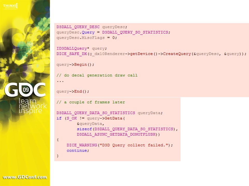
Implementation – Queries
Grouped together with each decal generation draw call Result is used to ”commit” decals into their decal sets or discard them if no triangles were written Result of this is that we need to round trip to the CPU to determine how to draw the decals. Will discuss later how to avoid this.

47
Implementation – Queries
Issues Buffer overflows Syncronization No way of knowing where in the buffer vertices were written Only have NumPrimitivesWritten and PrimitiveStorageNeeded

48
Implementation – Queries
Solution: When an overflow is detected the buffer is wrapped around. If any decals are partially written they are discarded and redispatched. We know that all dispatched draw calls / queries execute in given order

49
Room for improvement – could re-dispatch the decal if it was partially written, or try to figure out a good threshold before the buffer runs out to reset the buffer.

50
Results Show videos here.

51
Decal movie

52
Skinned decal movie

53
Future Work Rewrite to make use of DrawAuto()
Experiment more with material masking possibilites Port to DX11 Compute Shader Implement GPU-based ray/mesh intersection tests SLI/Crossfire For DrawAuto() we need to use and über-shader plus insert material index into vertex stream. This will reduce latency (GPU can start drawing as soon as decal geometry is written – dont need to keep track of indices) and speed (don’t need to sort cpu decals on surface shader).
 we need to use and über-shader plus insert material index into vertex stream. This will reduce latency (GPU can start drawing as soon as decal geometry is written – dont need to keep track of indices) and speed (don’t need to sort cpu decals on surface shader).")
54
Questions? Contact: johan.andersson@dice.se daniel.johansson@dice.se
igetyourfail.com

55
References [1] Zhang et al. ”Parallel-Split Shadow Maps on Programmable GPUs". GPU Gems 3. [2] Valient, Michael. "Stable Rendering of Cascaded Shadow Maps". ShaderX6
![References [1] Zhang et al. Parallel-Split Shadow Maps on Programmable GPUs . GPU Gems 3.](http://slideplayer.com/slide/220229/1/images/55/References+%5B1%5D+Zhang+et+al.+Parallel-Split+Shadow+Maps+on+Programmable+GPUs+.+GPU+Gems+3..jpg "[2] Valient, Michael. Stable Rendering of Cascaded Shadow Maps . ShaderX6.")
Similar presentations


 ysys y s = y r (n/z r ) zrzr.>")


