Download presentation
Presentation is loading. Please wait.

1
Amana Amana ALW895SAC This presentation uses the Amana ALW895SAC washer for demonstration purposes. This washer is rated as an energy star model. It also has an automatic temperature control option. The Herrin style transmission has been incorporated into the Amana product.

2
The washer has a Stainless steel tub.

3
Shipping plug must be removed before operating machine
Important installation note

4
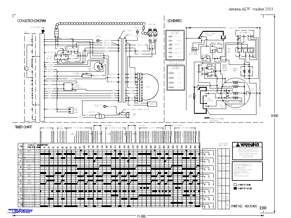
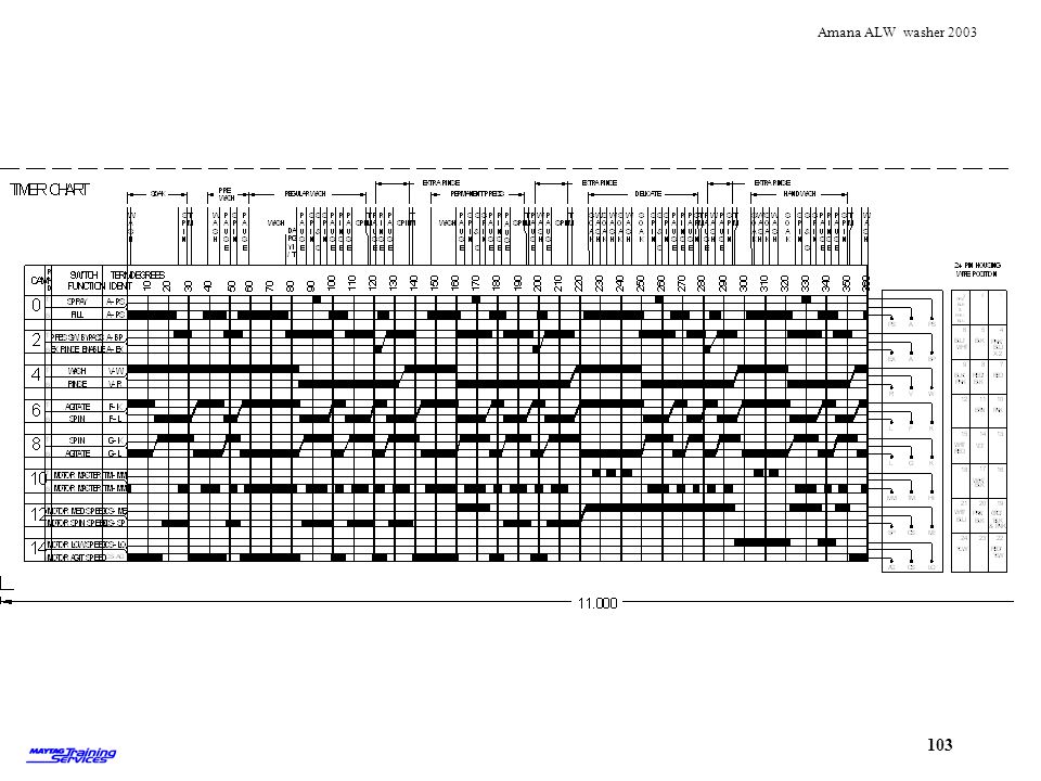
Electro-mechanical Timer
Water Level Switch Automatic Temp Control Motor Speed Control Extra Rinse The washer is equipped with an electro-mechanical timer, water level switch, extra rinse switch, motor speed switch and automatic temperature control.

5
Removing Console To drop the console remove two 1/4” screws from the top of console cover The console can be tipped forward to access the hinge brackets holding the console in place To drop the console remove the two ¼” screws from the top of the console cover.

6
Console Brackets Brackets
Two brackets act as hinges to allow the console to be tipped forward. Loosening the two 5/16” screws allow the console to be removed completely

7
Removing Console Assembly
To remove console; disconnect wires to lid switch,line harness, main wiring harness, pressure hose and ground wires (also ATC harness if equipped)
")
8
Component identification
Timer Extra Rinse Switch Speed Switch Pressure Switch Water Temperature Switch ATC Board Control components are easily accessible with console dropped

9
Releasing Timer Knob lock
To remove the timer knob, push the knob in and pull the black tab on the back of the timer out 3/16” To remove the timer knob, push in on the knob and then pull the black tab out about 3/16”.

10
Knob lock close up Pulling the black tab back unlocks the knob so it can be removed Pulling the black tab back unlocks the knob so it can be removed

11
Removing Timer Skirt To remove the timer skirt – insert a cloth under the skirt and pull up Position a piece of cloth under the knob and pull the skirt off.

12
Lift tab/slide and lift out Remove screw Remove connector
Release lock Lift tab/slide and lift out Remove screw Remove connector To remove timer: release wiring connector lock remove the connector block remove screw Lift the plastic lock tab Slide and lift the timer assembly

13
Make careful not to damage adjoining switches when removing
Removing timer Timer removed Make careful not to damage adjoining switches when removing

14
Removing Console Components
Remove knobs by placing cloth under knob and pulling up Place cloth under knob and pull off

15
Removing Pressure Switch
Remove screw Rotate switch counterclockwise and pull out To replace pressure switch, first remove screw and then twist switch counter-clockwise

16
Removing speed switch The speed switch is secured by two plastic locking tabs, release tabs to remove switch The speed switch is held in place by two plastic tabs. Depress the tabs while pulling on the switch.

17
Rotate switch counterclockwise and lift out
To remove the water temperature switch, rotate counterclockwise and pull out

18
Removing ATC To remove ATC board – carefully pull out of connector
Carefully pull the ATC board out of the connector To remove ATC board – carefully pull out of connector

20
Removing lower access panel
Remove two 5/16”screws securing the bottom access panel Remove two 5/16”screws securing the bottom access panel

21
Releasing spring clip Insert putty knife approximately 2.5” from side to release clips After removing the two lower screws it might be necessary to release two springs clips between the upper and lower panels. The clips are located approximately 2.5” in from each side. Use a plastic putty knife or a metal blade wrapped with tape to reduce the chance of scratching the paint.

22
Remove the two 5/16” screws securing the main panel in place

24
Front and top panel removed
Front panels and top removed Front panels and top removed

25
Lid switch actuating assembly
Viewed with the top raised

26
Water valve Water inlet assembly

27
Thermistor The thermistor is installed in the inlet hose. The resistance of the thermistor changes with temperature. Thermistor used on ATC model. Senses temperature of water entering tub

28
Pressure dome and hose Pressure tube and dome Pressure tube and dome

29
Motor compartment Motor Drain hoses Suspension springs Pump
View of components

30
Removing agitator Grasp the agitator base and jerk up Caution! the agitator will break loose suddenly, keep your head clear! To remove the agitator:firmly grasp the agitator base at the 9:00 and 3:00 o’clock position. With your head to one side jerk up. BE CAREFUL! The agitator will break loose suddenly.

31
Agitator removed Remove agitator

32
Outer Tub Cover Splash Ring To remove: release clips and lift off To remove: push down on cover, release clips, and lift off

33
Removing the agitator allows access to the drive bell
Remove ½” bolt Lift off To remove the drive bell: remove the ½” bolt and lift off

34
Removing Inner Tub Remove four ½” bolts securing the inner tub
Lift out tub Removing Inner Tub To remove the inner tub, remove the four ½” bolts and lift the tub out

35
Filter Filter lifts off Filter lifts off

36
Seal nut tool Wrench 35-2968 Seal Nut Tool 22002898
Install the seal nut tool and use the spanner wrench to turn

37
Removing seal nut Seal Nut
Rotate the seal nut counterclockwise to loosen. A hammer might have to be used on the wrench to break the nut loose.

38
Seal nut off shaft showing o ring
Lift off the seal nut Remove the O Ring Always replace the O ring when servicing

39
Spanner Wrench Part# Use the spanner wrench to remove the seal hub

40
View of seal View of the top of the seal View of the top of the lip seal. Triple lip seal to be introduced series 15 and newer

42
7 Springs make up the suspension system
4 Springs are accessible from the front and sides of the machine 7 Springs make up the suspension system 4 Springs are accessible from the front and sides of the machine

43
Viewed from the back with cabinet removed
3 rear springs 3 rear springs viewed from the back with cabinet removed. The smaller center spring is designed to eliminate the need for the counterweight used on the older product The two suspension springs should be installed upside down compared to the front suspension rings to prevent contact during spin

44
Wrong spring installation
If the rear springs are installed as shown, there is a possibility the springs will rub together during spin and be noisy.

45
Correct Viewed from the back with cabinet removed

46
Proper installation of hooks into base. Do not cross hooks!
When installing springs, make sure the hooks are installed into the base as shown If the springs are crossed, noise and vibration could result. Proper installation of hooks into base Do not cross hooks!

47
Removing suspension spring
Remove the four front springs first and then remove rear springs –the smaller seventh spring last Removing suspension spring Use the spring hook to remove the suspension springs

48
Spring being unhooked Releasing spring

49
Installing the seventh spring

50
Springs Removed Springs removed All springs removed

51
Rolling out tub assembly
Remove drain hose and roll the tub assembly out the front Roll the tub assembly out the front of the cabinet

52
Friction ring and milk stool
The milk stool sets on the friction ring- the friction ring allows the tub assembly to move in order to center itself

54
View of motor and pump Tub assembly viewed from the bottom

55
Idler tension spring Carefully remove idler tension spring before further disassembly to reduce the chance of damage Carefully remove idler tension spring before further disassembly to reduce the chance of damage

56
T-25 torx tool Pump is held in place with three T-25 Torx screws
The pump is secured with three T-25 Torx screws

57
Remove the three Torx screws and lift off
Removing Pump Remove the three Torx screws and lift off

58
Components under pump Idler Pulley Motor Drive Pulley Start Capacitor
Idler Lever and Tension Spring Start Capacitor Idler Pulley Motor Drive Pulley With the pump removed, there is access to the belt and pulleys

59
Idler pulley operation
Spring tension forces idler pulley against back side of the drive belt Spring tension forces idler pulley against back side of the drive belt

60
Correct belt routing is outside of inner pump support
Incorrect belt routing Pump installation note - proper belt routing

61
Idler pulley snap ring The idler pulley is secured to the idler shaft with a snap ring The idler pulley is secured to the idler shaft with a snap ring

62
Accessing the Transmission
When accessing the transmission the motor assembly can be removed as a unit there is no need to remove the pump as shown on the previous slides To access the transmission, remove the motor and pump assembly as a unit.

63
Removing drain hose Remove tub hose Remove the remaining drain hose

64
Remove Spring to release tension on idler pulley and roll drive belt off tub pulley

65
Removing motor bolts Remove the four ½” ‘bolts securing the motor assembly Remove the four ½” ‘bolts securing the motor assembly

66
Motor/pump removed Remove the motor/pump assembly
Remove the motor assembly and set to the side

67
Remove bolt and cam to free pulley and transmission
This step is not necessary if removing the transmission and milk stool as an assembly

68
Removing bolts holding outer tub on
Next remove the six ½” bolts securing the milk stool to the outer tub and remove Remove the six screws securing the milk stool to the outer tub

69
Removing transmission and milk stool
Remove the transmission and milk stool Lift out the transmission

70
Tub seal and bearing Seal and bearing assembly Seal assembly

71
Instruction sheet for brake/bearing tool
A kit has been developed to service the new seal assembly part# The kit includes an instruction sheet #

72
Bearing removal tool part#12002012
Bearing tool part# Bearing removal tool part# The kit consists of the old brake tool, a plastic dome and washers. The part number of the tool only is Upgrade Kit Number – converts LA-2004 (old tool) to
 to")
73
Install plastic bell and washers on shaft and fasten with nut
Install brake removal tool, washer and threaded shaft from the bottom side of outer tub To remove old seal: Install the brake tool and shaft up through the tub. Install the dome, washer and nut onto the shaft

74
Pulling out bearing Tighten the nut clockwise until the seal/bearing assembly is pulled out of the housing Tighten nut clockwise until the tool pulls the seal assembly out of the housing.

75
View of bearing removed
Bearing and seal removed

76
Bottom side of assembly showing spin bearing
Top side of assembly showing seal View of the seal/bearing assembly

77
Close up of seal Vaseline is used as a lubricant on the seal

78
Insert replacement seal assembly and large washer from kit
To install new tool: Lubricate inside of seal area with a coating of Vaseline Start new bearing/seal into place. Add washer from kit.

79
Insert brake tool and threaded shaft
Insert brake tool shaft

80
Install plastic dome and washer over threaded shaft
Add plastic dome, washer and nut to shaft

81
Install nut and tighten to seat new seal
Tighten nut Center washer and bell Pull new seal into place. Install nut and tighten to seat new seal assembly

82
View of lip seal The lip seal is replaceable Removing lip seal

83
Seal protector and new seal
Seal removal tool Seal protector and new seal Part # Lip seal tool part# Use the lip seal tool to remove and install.

84
The instructions for using the seal tool are shipped with the kit.

85
Using lip seal tool Removing oil seal Back off bolt and install tool over shaft. Start self tapping thread into seal Back off the bolt and install the tool over the transmission shaft.

86
Use a wrench to turn tool into seal
Wrench on tool Use a wrench to turn tool into seal Once the tool is firmly seated in old seal, turn top bolt clockwise to pull out seal Start threading the tool into the old seal. Once the tool starts to cut into the seal, turn the bolt to pull out the seal.

87
Seal removed Old seal removed Seal removed

88
Install new seal onto seal protector and insert over shaft
Install new seal onto seal protector and insert over shaft. Use seal tool to drive new seal into place. Remove seal protector Installing new seal Install a new seal onto the seal protector Place the seal onto the transmission shaft and start in place. Use the tool and small hammer to tap the seal into place.

90
Remove brake pad Remove two 3/8” bolts Brake pad removal

91
Rotate transmission to allow insertion of new brake pad
Insert pad and install bolts

92
Removing the motor and pump with the tub in the machine
Disconnecting hoses Removing the motor and pump with the tub in the machine To remove the motor/pump assembly: Remove idler tension spring Remove belt Remove drain hoses Remove idler tension spring Remove belt Remove drain hoses

93
Removing suspension spring
4. Remove suspension spring Remove suspension spring

94
Removing Motor Bolts 5. Remove four ½” bolts Remove four ½” bolts

95
Motor assembly removed
Remove assembly

96
Remove pump screws Remove the three T-25 Torx screws to remove pump

97
Pulling pump off Remove pump Remove pump

98
View of pulleys and belts
With pump removed, belt and pulleys can be serviced Belt and pulley can be serviced

104
ANY QUESTIONS?

Similar presentations


 Grants Chapter 6.>")
