Download presentation
Presentation is loading. Please wait.

1
A/V Tech Basics for Archivists AMIA 2013 Eric Wenocur Lab Tech Systems Silver Spring, MD eric@lab-tech-systems.com Eric Wenocur Lab Tech Systems Silver Spring, MD eric@lab-tech-systems.com

2
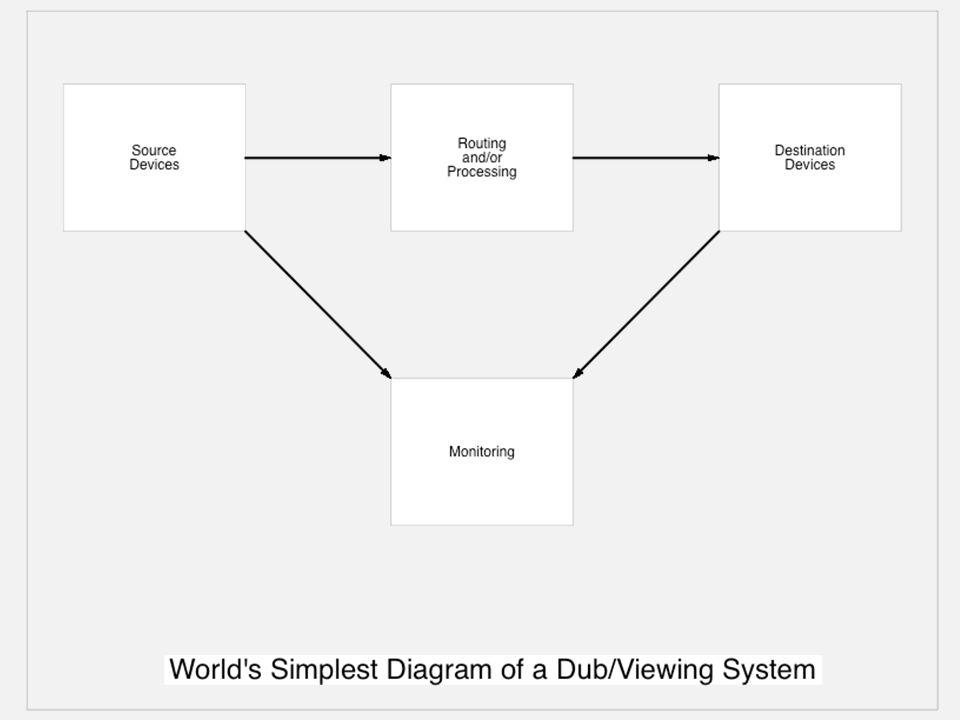
2 Workshop Overview Elements of a dub/viewing system Video signals, connections, monitoring Audio signals, connections, monitoring Videotape machines Simple troubleshooting Elements of a dub/viewing system Video signals, connections, monitoring Audio signals, connections, monitoring Videotape machines Simple troubleshooting

4
4

5
5

7
7 Composite Video Luminance and chrominance are carried together on one wire, along with sync signals. Once most pervasive format, but poorest quality due to need for separating luma and chroma at displays and other devices. Luminance and chrominance are carried together on one wire, along with sync signals. Once most pervasive format, but poorest quality due to need for separating luma and chroma at displays and other devices.

8
8 Component Video Video is carried on three wires, either as RGB or color-difference (Y, R-Y, B-Y). Became prominent in professional video with Betacam. Maintains better image quality. Several variants to contend with… Video is carried on three wires, either as RGB or color-difference (Y, R-Y, B-Y). Became prominent in professional video with Betacam. Maintains better image quality. Several variants to contend with…
. Became prominent in professional video with Betacam. Maintains better image quality. Several variants to contend with….")
9
9 Video Signal Formats & Connectors F Cable: RF (cable TV) RGB Set: Component Analog BNC Cable: Analog & Digital Video Y/C Cable: S-Video Video Patch Jack
 RGB Set: Component Analog BNC Cable: Analog & Digital Video Y/C Cable: S-Video Video Patch Jack")
10
10 Critical Video Connection Rules Video signal lines must terminate in 75-ohms at the final connection point! You cannot passively split or combine video signals! You can passively loop signals between devices, but must terminate at the end! Video signal lines must terminate in 75-ohms at the final connection point! You cannot passively split or combine video signals! You can passively loop signals between devices, but must terminate at the end!

11
11

12
12 Signal Flow Strategies Maintain Signal Quality Accurate Monitoring What is the signal really like? How will it look/sound elsewhere? Flexibility Maintain Signal Quality Accurate Monitoring What is the signal really like? How will it look/sound elsewhere? Flexibility

14
14 The Monitor as a Reference Apply a known good signal Adjust the monitor Leave it alone! Apply a known good signal Adjust the monitor Leave it alone!

15
15 Todays Display Situation CRTs no longer being made Standards were based on CRT performance Fixed-pixel displays often worse for viewing standard-def due to scaling artifacts Unpredictable color-rendering, pixel depth between various displays CRTs no longer being made Standards were based on CRT performance Fixed-pixel displays often worse for viewing standard-def due to scaling artifacts Unpredictable color-rendering, pixel depth between various displays

16
16 Typical Monitor Controls

17
17 Typical Monitor Rear View

18
18 Why Bars & Tone Matter! How does anyone know what the Content is supposed to look like? And furthermore… How does anyone know what ANYTHING is supposed to look like?

19
19 Why Bars & Tone Matter! We know what colorbars are supposed to look like (they have been defined by Standards). Establish a known reference for Content ( which includes the conditions at the time) Use for setting up tape playback to produce the desired result Useful for verifying proper operation of equipment and systems We know what colorbars are supposed to look like (they have been defined by Standards). Establish a known reference for Content ( which includes the conditions at the time) Use for setting up tape playback to produce the desired result Useful for verifying proper operation of equipment and systems
. Establish a known reference for Content ( which includes the conditions at the time) Use for setting up tape playback to produce the desired result Useful for verifying proper operation of equipment and systems We know what colorbars are supposed to look like (they have been defined by Standards). Establish a known reference for Content ( which includes the conditions at the time) Use for setting up tape playback to produce the desired result Useful for verifying proper operation of equipment and systems.")
20
20 Where to get test signals? Facility test generator Non-linear editor Many newer VTRs Professional cameras Facility test generator Non-linear editor Many newer VTRs Professional cameras

21
21 How do we know if the TEST SIGNAL is good?

22
22 Waveform Monitor/Vectorscope Conventional & Rasterizing

23
23 Waveform Monitor & Vectorscope Measure luminance and chrominance levels Find appropriate black or white levels, appropriate saturation, hue (composite) Display color-balance information (for color-correction) Find flaws in video, track down system problems Measure luminance and chrominance levels Find appropriate black or white levels, appropriate saturation, hue (composite) Display color-balance information (for color-correction) Find flaws in video, track down system problems
 Display color-balance information (for color-correction) Find flaws in video, track down system problems Measure luminance and chrominance levels Find appropriate black or white levels, appropriate saturation, hue (composite) Display color-balance information (for color-correction) Find flaws in video, track down system problems")
24
24 Waveform Monitor Peak white patch Bar luminance steps Chroma packets H-sync pulse Gray Bar Baseline (0 ire) Black level (7.5)
 Black level (7.5)")
25
25 Vectorscope Colorbar Vectors Colorburst VectorNo chroma at center

26
26 Some Common Video System Problems No termination or double-termination (watch those switches and terminators) Two signals feeding same input (improperly using passive loop-thrus) Component cable mixup (Y, R-Y, B-Y) Component mode error (YRB vs. RGB) No termination or double-termination (watch those switches and terminators) Two signals feeding same input (improperly using passive loop-thrus) Component cable mixup (Y, R-Y, B-Y) Component mode error (YRB vs. RGB)
 No termination or double-termination (watch those switches and terminators) Two signals feeding same input (improperly using passive loop-thrus) Component cable mixup (Y, R-Y, B-Y) Component mode error (YRB vs. RGB).")
27
27 Video Unterminated

28
28 Video Double-terminated

29
29 Component Cable Mixup Correct R-Y & B-Y Swapped

30
A/V Tech Basics for Archivists BREAK 1 Eric Wenocur Lab Tech Systems Silver Spring, MD eric@lab-tech-systems.com Eric Wenocur Lab Tech Systems Silver Spring, MD eric@lab-tech-systems.com

31
31 Audio Operating Level There are roughly three categories of audio operating level: Mic, Line and Speaker. Line has a wide range of levels in use between equipment. Professional equipment line levels are typically 10-20 dB higher than consumer or prosumer. Pro level is often referred to as +4 Consumer level is often known as -10 It is not wise to connect these devices together without proper interfacing to compensate! There are roughly three categories of audio operating level: Mic, Line and Speaker. Line has a wide range of levels in use between equipment. Professional equipment line levels are typically 10-20 dB higher than consumer or prosumer. Pro level is often referred to as +4 Consumer level is often known as -10 It is not wise to connect these devices together without proper interfacing to compensate!

32
32 Balanced and Unbalanced Connections This has nothing to do with tonal balance. Balanced audio connections cancel out noise picked up on the cable. Balanced typically uses two signal wires and a shield, connectors have three terminals. Balanced is usually also pro (+4) level. You can connect balanced and unbalanced together but it requires knowledge! This has nothing to do with tonal balance. Balanced audio connections cancel out noise picked up on the cable. Balanced typically uses two signal wires and a shield, connectors have three terminals. Balanced is usually also pro (+4) level. You can connect balanced and unbalanced together but it requires knowledge!
 level. You can connect balanced and unbalanced together but it requires knowledge. This has nothing to do with tonal balance. Balanced audio connections cancel out noise picked up on the cable. Balanced typically uses two signal wires and a shield, connectors have three terminals. Balanced is usually also pro (+4) level. You can connect balanced and unbalanced together but it requires knowledge!.")
33
33 Common Audio Connectors Phone plugs Terminal Block XLR plugs RCA plug Mini plug

34
34 Issues with Audio Connectors The same types of connectors are often used for different types of signals (eg: XLRs for both mic and line level). Some connectors look similar but arent (eg: 2- and 3-conductor phone plugs). Preponderance of unbalanced consumer connectors (RCA phono plug) on gear. The same types of connectors are often used for different types of signals (eg: XLRs for both mic and line level). Some connectors look similar but arent (eg: 2- and 3-conductor phone plugs). Preponderance of unbalanced consumer connectors (RCA phono plug) on gear.
. Preponderance of unbalanced consumer connectors (RCA phono plug) on gear. The same types of connectors are often used for different types of signals (eg: XLRs for both mic and line level). Some connectors look similar but arent (eg: 2- and 3-conductor phone plugs). Preponderance of unbalanced consumer connectors (RCA phono plug) on gear..")
35
35

36
36 Broadcast-style Audio Patch Panel

37
37

38
38 Uh oh…

39
39 Audio Metering Why does the same audio look different on different meters? Why does the same audio look different on different meters?

40
40 Audio Metering Mechanical analog or electronic bargraph? Where is 0? Different for analog and digital applications. How large is the scale range? Meters vary from 23dB to 60 or 80dB scales. How quickly does the meter respond to changes in audio? Ballistics can be average, peak, PPM, etc. Mechanical analog or electronic bargraph? Where is 0? Different for analog and digital applications. How large is the scale range? Meters vary from 23dB to 60 or 80dB scales. How quickly does the meter respond to changes in audio? Ballistics can be average, peak, PPM, etc.

41
41 Audio Metering Analog Analog audio will distort when level is too high, but the effect is usually gradual. Analog meters were designed to show average levels around 0VU. There is usually 10-20 dB headroom left above 0VU before distortion. Tone should be at 0VU. Analog audio will distort when level is too high, but the effect is usually gradual. Analog meters were designed to show average levels around 0VU. There is usually 10-20 dB headroom left above 0VU before distortion. Tone should be at 0VU.

42
42 Audio Metering Digital Digital audio has an absolute upper limit which is called Full Scale. Meters for digital equipment read in terms of dBFS (decibels relative to Full Scale) Maximum possible level is at 0 dBFS. Tone is usually at about -20 dBFS so there is 20dB of headroom before overload. Digital audio has an absolute upper limit which is called Full Scale. Meters for digital equipment read in terms of dBFS (decibels relative to Full Scale) Maximum possible level is at 0 dBFS. Tone is usually at about -20 dBFS so there is 20dB of headroom before overload.
 Maximum possible level is at 0 dBFS. Tone is usually at about -20 dBFS so there is 20dB of headroom before overload. Digital audio has an absolute upper limit which is called Full Scale. Meters for digital equipment read in terms of dBFS (decibels relative to Full Scale) Maximum possible level is at 0 dBFS. Tone is usually at about -20 dBFS so there is 20dB of headroom before overload..")
43
43 Typical Audio Flaws Clipping and other distortion Excessive noise beneath audio Tonal imbalance Channel phase reversal Audio/video lip-sync errors Clipping and other distortion Excessive noise beneath audio Tonal imbalance Channel phase reversal Audio/video lip-sync errors

44
44 Basic Mixer Sections Input Channels Process signals entering mixer (input jacks, mic preamp, equalizer, channel fader) Buses & Outputs Combine signals together and send out (bus assign, bus master level, output jacks) Monitoring Controls speaker volume and what is heard (mon source select, speaker select, speaker volume) Input Channels Process signals entering mixer (input jacks, mic preamp, equalizer, channel fader) Buses & Outputs Combine signals together and send out (bus assign, bus master level, output jacks) Monitoring Controls speaker volume and what is heard (mon source select, speaker select, speaker volume)
 Buses & Outputs Combine signals together and send out (bus assign, bus master level, output jacks) Monitoring Controls speaker volume and what is heard (mon source select, speaker select, speaker volume) Input Channels Process signals entering mixer (input jacks, mic preamp, equalizer, channel fader) Buses & Outputs Combine signals together and send out (bus assign, bus master level, output jacks) Monitoring Controls speaker volume and what is heard (mon source select, speaker select, speaker volume)")
45
45 Basic Mixer Sections Monitor Section Output Bus Masters Aux Bus Masters & Misc. Input Channel Strips

46
46 Mixer Flow #1 Input Channels Buses Outputs

47
47 Mixer Flow #2 Input Channel Aux Send with Pre/Post Select Buses & Outputs

48
48 Mixer Flow #3 Added Monitor Section

49
49 Typical Mixer Connections Aux Sends Sub Bus Outs Tape Ins/ Outs Main Bus Outs CR Mon Outs Input Channels Channel Insert Line Input Mic Input

50
50 A Word about Phantom Power 48 volts DC used to power condenser microphones This voltage can damage other equipment. Unless you are using a condensor mic LEAVE IT OFF! 48 volts DC used to power condenser microphones This voltage can damage other equipment. Unless you are using a condensor mic LEAVE IT OFF!

51
A/V Tech Basics for Archivists BREAK 2 Eric Wenocur Lab Tech Systems Silver Spring, MD eric@lab-tech-systems.com Eric Wenocur Lab Tech Systems Silver Spring, MD eric@lab-tech-systems.com

52
52 Videotape Formats Legacy Analog: VHS, S-VHS, Hi-8 3/4 (U-matic), 1 Betacam, Beta SP Legacy Analog: VHS, S-VHS, Hi-8 3/4 (U-matic), 1 Betacam, Beta SP
, 1 Betacam, Beta SP Legacy Analog: VHS, S-VHS, Hi-8 3/4 (U-matic), 1 Betacam, Beta SP")
53
53 Videotape Formats Legacy Digital: D-1 (component) D-2, D-3 (composite) Legacy Digital: D-1 (component) D-2, D-3 (composite)
 D-2, D-3 (composite) Legacy Digital: D-1 (component) D-2, D-3 (composite)")
54
54 Videotape Formats Digital Betacam Family: Digi Beta Betacam SX Betacam IMX Digital Betacam Family: Digi Beta Betacam SX Betacam IMX

55
55 Videotape Formats Other Digital: D-5 (Panasonic) HDCam (Sony) D-9 (Digital-S) Other Digital: D-5 (Panasonic) HDCam (Sony) D-9 (Digital-S)
 HDCam (Sony) D-9 (Digital-S) Other Digital: D-5 (Panasonic) HDCam (Sony) D-9 (Digital-S)")
56
56 Videotape Formats DV-based: DV, mini-DV DVCam DVCPro 25/50/100 HDV DV-based: DV, mini-DV DVCam DVCPro 25/50/100 HDV

57
57 PVW-2800 Internal View Cassette Elevator Video & Audio Circuit Boards Control & Misc. Circuit Boards Video Head Drum Audio Heads Capstan Threading Motor

58
58 VTR Systems Video processing Audio processing Capstan servo -- controls tape movement Drum servo -- controls head drum Video processing Audio processing Capstan servo -- controls tape movement Drum servo -- controls head drum

59
59 VTR Servos Lock to Reference input during playback Lock to Record input during recording Internal TBC (timebase corrector) may lock differently than servo system Lock to Reference input during playback Lock to Record input during recording Internal TBC (timebase corrector) may lock differently than servo system
 may lock differently than servo system Lock to Reference input during playback Lock to Record input during recording Internal TBC (timebase corrector) may lock differently than servo system")
60
60 VTR Tape Tracks Longitudinal Audio Tracks Longitudinal Control Track Helical Video Tracks Longitudinal TC Track Similar for analog or digital formats

61
61 VTR Recording Modes E/E (electronics-to-electronics) -- passes input signals through to output Hard (crash) Record -- erases and records all tracks at once, no sync with previous recording Assemble Record -- erases and records all tracks, but picks up in sync with previous recording Insert Record -- only erases and records selected tracks (control track must be present!) E/E (electronics-to-electronics) -- passes input signals through to output Hard (crash) Record -- erases and records all tracks at once, no sync with previous recording Assemble Record -- erases and records all tracks, but picks up in sync with previous recording Insert Record -- only erases and records selected tracks (control track must be present!)
 -- passes input signals through to output Hard (crash) Record -- erases and records all tracks at once, no sync with previous recording Assemble Record -- erases and records all tracks, but picks up in sync with previous recording Insert Record -- only erases and records selected tracks (control track must be present!) E/E (electronics-to-electronics) -- passes input signals through to output Hard (crash) Record -- erases and records all tracks at once, no sync with previous recording Assemble Record -- erases and records all tracks, but picks up in sync with previous recording Insert Record -- only erases and records selected tracks (control track must be present!)")
62
62 VTR Front Panel Audio Level Controls & Meters Transport Controls Editing Controls Remote Select Timecode Display & Menus Timecode Controls may be various places!

63
63 VTR Rear Panel Connectors Analog Audio I/O d d d d d Analog Video Inputs Analog Video Ouputs Remote Control And Misc. Digital Audio I/O Digital Video I/O

64
64 Menus & Special Switches Ref Auto/Manual: Set to AUTO Audio input 600-ohm terminations: Set to OFF Audio input level: Set to HIGH Ref Auto/Manual: Set to AUTO Audio input 600-ohm terminations: Set to OFF Audio input level: Set to HIGH If your VTR has any of the following switches on the back…

65
65 Menus & Special Switches When in doubt use the Factory Default settings!

66
66 A few words about Reference, Genlock and Timing Reference signals are used to make equipment produce output signals in sync with each other. Reference is about playback, not recording; the recording device always locks to its input signal. To genlock means locking a device to a reference signal. Timing is about the relationship between two devices that both feed a third device (such as cameras feeding a switcher). There is NO timing in a dub/viewing or NLE system! Having devices locked to a common reference when possible is recommended, but not critical in most cases. Reference signals are used to make equipment produce output signals in sync with each other. Reference is about playback, not recording; the recording device always locks to its input signal. To genlock means locking a device to a reference signal. Timing is about the relationship between two devices that both feed a third device (such as cameras feeding a switcher). There is NO timing in a dub/viewing or NLE system! Having devices locked to a common reference when possible is recommended, but not critical in most cases.
. There is NO timing in a dub/viewing or NLE system. Having devices locked to a common reference when possible is recommended, but not critical in most cases. Reference signals are used to make equipment produce output signals in sync with each other. Reference is about playback, not recording; the recording device always locks to its input signal. To genlock means locking a device to a reference signal. Timing is about the relationship between two devices that both feed a third device (such as cameras feeding a switcher). There is NO timing in a dub/viewing or NLE system. Having devices locked to a common reference when possible is recommended, but not critical in most cases..")
67
67 Simple Troubleshooting Use good observation techniques: Note all conditions during problem Note conditions leading up to problem When was the last good operation? Has anything changed? Be clear about meaning of words! Use good observation techniques: Note all conditions during problem Note conditions leading up to problem When was the last good operation? Has anything changed? Be clear about meaning of words!

68
68 Troubleshooting Strategies It pays to know how things are SUPPOSED to work. Start with known good signals (bars and tone), good path and monitoring. Change one thing and observe… Swap things: cables, equipment, software Cut problem in half It pays to know how things are SUPPOSED to work. Start with known good signals (bars and tone), good path and monitoring. Change one thing and observe… Swap things: cables, equipment, software Cut problem in half
, good path and monitoring. Change one thing and observe… Swap things: cables, equipment, software Cut problem in half It pays to know how things are SUPPOSED to work. Start with known good signals (bars and tone), good path and monitoring. Change one thing and observe… Swap things: cables, equipment, software Cut problem in half.")
69
69 Troubleshooting Strategies Manuals are like GOLD! (especially for legacy gear) Manuals are like GOLD! (especially for legacy gear)
 Manuals are like GOLD. (especially for legacy gear).")
70
Please send me feedback on this workshop! Eric Wenocur Lab Tech Systems Silver Spring, MD eric@lab-tech-systems.com Eric Wenocur Lab Tech Systems Silver Spring, MD eric@lab-tech-systems.com Copyright 2013 Eric Wenocur All photos copyright their respective owners. Copyright 2013 Eric Wenocur All photos copyright their respective owners.

Similar presentations


>")


 Grants Chapter 6.>")


