Download presentation
Presentation is loading. Please wait.

1
Headed Concrete Anchors (HCA)
PCI 6th Edition Headed Concrete Anchors (HCA)
")
2
Presentation Outine Research Background Steel Capacity
Concrete Tension Capacity Tension Example Concrete Shear Capacity Shear Example Interaction Example

3
Background for Headed Concrete Anchor Design
Anchorage to concrete and the design of welded headed studs has undergone a significant transformation since the Fifth Edition of the Handbook. “Concrete Capacity Design” (CCD) approach has been incorporated into ACI Appendix D
 approach has been incorporated into ACI Appendix D.")
4
Headed Concrete Anchor Design History
The shear capacity equations are based on PCI sponsored research The Tension capacity equations are based on the ACI Appendix D equations only modified for cracking and common PCI variable names

5
Background for Headed Concrete Anchor Design
PCI sponsored an extensive research project, conducted by Wiss, Janney, Elstner Associates, Inc., (WJE), to study design criteria of headed stud groups loaded in shear and the combined effects of shear and tension Section D.4.2 of ACI specifically permits alternate procedures, providing the test results met a 5% fractile criteria The tension equations are as shown in the ACI code, except for the cracking coefficients. The shear provisions are based on the PCI sponsored tests. Equations derived from those tests meet the “5% fractile” criterion discussed above. For combined shear and tension, the PCI sponsored tests did not find significant variance from the ACI code recommendations.
, to study design criteria of headed stud groups loaded in shear and the combined effects of shear and tension. Section D.4.2 of ACI specifically permits alternate procedures, providing the test results met a 5% fractile criteria. The tension equations are as shown in the ACI code, except for the cracking coefficients. The shear provisions are based on the PCI sponsored tests. Equations derived from those tests meet the 5% fractile criterion discussed above. For combined shear and tension, the PCI sponsored tests did not find significant variance from the ACI code recommendations.")
6
Supplemental Reinforcement
Appendix D, Commentary “… supplementary reinforcement in the direction of load, confining reinforcement, or both, can greatly enhance the strength and ductility of the anchor connection.” “Reinforcement oriented in the direction of load and proportioned to resist the total load within the breakout prism, and fully anchored on both side of the breakout planes, may be provided instead of calculating breakout capacity.”

7
HCA Design Principles Performance based on the location of the stud relative to the member edges Shear design capacity can be increased with confinement reinforcement In tension, ductility can be provided by reinforcement that crosses the potential failure surfaces

8
HCA Design Principles Designed to resist
Tension Shear Interaction of the two The design equations are applicable to studs which are welded to steel plates or other structural members and embedded in unconfined concrete

9
HCA Design Principles Where feasible, connection failure should be defined as yielding of the stud material The groups strength is taken as the smaller of either the concrete or steel capacity The minimum plate thickness to which studs are attached should be ½ the diameter of the stud Thicker plates may be required for bending resistance or to ensure a more uniform load distribution to the attached studs

10
Stainless Steel Studs Can be welded to either stainless steel or mild carbon steel Fully annealed stainless steel studs are recommended when welding stainless steel studs to a mild carbon steel base metal Annealed stud use has been shown to be imperative for stainless steel studs welded to carbon steel plates subject to repetitive or cyclic loads

11
Stud Dimensions Table Page 6-12

12
Steel Capacity Both Shear and Tension governed by same basic equation
Strength reduction factor is a function of shear or tension The ultimate strength is based on Fut and not Fy

13
Steel Capacity fVs = fNs = f·n·Ase·fut Where
f = steel strength reduction factor = 0.65 (shear) = 0.75 (tension) Vs = nominal shear strength steel capacity Ns = nominal tensile strength steel capacity n = number of headed studs in group Ase = nominal area of the headed stud shank fut = ultimate tensile strength of the stud steel
 = 0.75 (tension) Vs = nominal shear strength steel capacity. Ns = nominal tensile strength steel capacity. n = number of headed studs in group. Ase = nominal area of the headed stud shank. fut = ultimate tensile strength of the stud steel.")
14
Material Properties Adapted from AWS D1.1-02 Table 6.5.1.1 page 6-11
shows the current minimum tensile and yield strengths for headed studs

15
Concrete Capacity ACI 318-02, Appendix D, “Anchoring to Concrete”
Cover many types of anchors In general results in more conservative designs than those shown in previous editions of this handbook

16
Cracked Concrete ACI assumes concrete is cracked
PCI assumes concrete is cracked All equations contain adjustment factors for cracked and un-cracked concrete Typical un-cracked regions of members Flexural compression zone Column or other compression members Typical precast concrete Typical cracked regions of members Flexural tension zones Potential of cracks during handling The PCI handbook method assumes that the majority of the precast member anchorages are in uncracked regions. This is reasonable because many precast members are prestressed and most of the anchorages designed for precast concrete are located where cracking is unlikely. Therefore, all of the tension and shear design equations in the handbook are written as “uncracked” equations. There is thus an additional cracked concrete factor, Ccrb for concrete breakout, or Ccrp for pullout, which reduces the headed stud capacity due to cracking.

17
The 5% fractile ACI 318-02, Section D.4.2 states, in part:
“…The nominal strength shall be based on the 5 percent fractile of the basic individual anchor strength…” Statistical concept that, simply stated, if a design equation is based on tests, 5 percent of the tests are allowed to fall below expected Capacity 5% Failures Test strength

18
The 5% fractile This allows us to say with 90 percent confidence that 95 percent of the test actual strengths exceed the equation thus derived Determination of the coefficient κ, associated with the 5 percent fractile (κσ) Based on sample population,n number of tests x the sample mean σ is the standard deviation of the sample set
 Based on sample population,n number of tests. x the sample mean. σ is the standard deviation of the sample set.")
19
The 5% fractile Example values of κ based on sample size are:

20
Strength Reduction Factor
Function of supplied confinement reinforcement f = 0.75 with reinforcement f = 0.70 with out reinforcement It is highly recommended that such confinement be provided around all concrete controlled headed stud connections.

21
Notation Definitions Edges Stud Layout Critical Dimensions
de1, de2, de3, de4 Stud Layout x1, x2, … y1, y2, … X, Y Critical Dimensions BED, SED

22
Concrete Tension Failure Modes
Design tensile strength is the minimum of the following modes: Breakout fNcb: usually the most critical failure mode Pullout fNph: function of bearing on the head of the stud Side-Face blowout fNsb: studs cannot be closer to an edge than 40% the effective height of the studs Each of these possible modes must be checked when a stud connection is designed

23
Concrete Tension Strength
fNcb: Breakout fNph: Pullout fNsb: Side-Face blowout fTn = Minimum of

24
Concrete Breakout Strength
Where: Ccrb = Cracked concrete factor, 1 uncracked, 0.8 Cracked AN = Projected surface area for a stud or group Yed,N =Modification for edge distance Cbs = Breakout strength coefficient

25
Effective Embedment Depth
hef = effective embedment depth For headed studs welded to a plate flush with the surface, it is the nominal length less the head thickness, plus the plate thickness (if fully recessed), deducting the stud burnoff lost during the welding process about 1/8 in.
, deducting the stud burnoff lost during the welding process about 1/8 in.")
26
Projected Surface Area, An
Based on 35o AN - calculated, or empirical equations are provided in the PCI handbook Critical edge distance is 1.5hef

27
No Edge Distance Restrictions
For a single stud, with de,min > 1.5hef

28
Side Edge Distance, Single Stud
de1 < 1.5hef

29
Side Edge Distance, Two Studs
de1 < 1.5hef By adding an additional stud, the length of the projected area increases by “X”

30
Side and Bottom Edge Distance, Multi Row and Columns
de1 < 1.5hef de2< 1.5hef By adding an additional row, the height of the projected area increases by “Y”

31
Edge Distance Modification
Yed,N = modification for edge distance de,min = minimum edge distance, top, bottom, and sides PCI also provides tables to directly calculate fNcb, but Cbs , Ccrb, and Yed,N must still be determined for the in situ condition

32
Determine Breakout Strength, fNcb
The PCI handbook provides a design guide to determine the breakout area

33
Determine Breakout Strength, fNcb
First find the edge condition that corresponds to the design condition

34
Eccentrically Loaded When the load application cannot be logically assumed concentric. Where: e′N = eccentricity of the tensile force relative to the center of the stud group e′N ≤ s/2

35
Pullout Strength Nominal pullout strength Where
Abrg = bearing area of the stud head = area of the head – area of the shank Ccrp = cracking coefficient (pullout) = 1.0 uncracked = 0.7 cracked The nominal pullout strength is a function of the bearing of the stud head against the concrete. The strength is:
 = 1.0 uncracked. = 0.7 cracked. The nominal pullout strength is a function of the bearing of the stud head against the concrete. The strength is:")
36
Side-Face Blowout Strength
For a single headed stud located close to an edge (de1 < 0.4hef) Where Nsb = Nominal side-face blowout strength de1 = Distance to closest edge Abrg = Bearing area of head
 Where. Nsb = Nominal side-face blowout strength. de1 = Distance to closest edge. Abrg = Bearing area of head.")
37
Side-Face Blowout Strength
If the single headed stud is located at a perpendicular distance, de2, less then 3de1 from an edge, Nsb, is multiplied by: Where:

38
Side-Face Blowout For multiple headed anchors located close to an edge (de1 < 0.4hef) Where so = spacing of the outer anchors along the edge in the group Nsb = nominal side-face blowout strength for a single anchor previously defined

39
Example: Stud Group Tension
Given: A flush-mounted base plate with four headed studs embedded in a corner of a 24 in. thick foundation slab (4) ¾ in. f headed studs welded to ½ in thick plate Nominal stud length = 8 in f′c = 4000 psi (normal weight concrete) fy = 60,000 psi
 ¾ in. f headed studs welded to ½ in thick plate. Nominal stud length = 8 in. f′c = 4000 psi (normal weight concrete) fy = 60,000 psi.")
40
Example: Stud Group Tension
Problem: Determine the design tension strength of the stud group

41
Solution Steps Step 1 – Determine effective depth
Step 2 – Check for edge effect Step 3 – Check concrete strength of stud group Step 4 – Check steel strength of stud group Step 5 – Determine tension capacity Step 6 – Check confinement steel

42
Step 1 – Effective Depth

43
Step 2 – Check for Edge Effect
Design aid, Case 4 X = 16 in. Y = 8 in. de1 = 4 in. de3 = 6 in. de1 and de3 > 1.5hef = 12 in. Edge effects apply de,min = 4 in.

44
Step 2 – Edge Factor

45
Step 3 – Breakout Strength

46
Step 3 – Pullout Strength

47
Step 3 – Side-Face Blowout Strength
de,min = 4 in. > 0.4hef = 4 in. > 0.4(8) = 3.2 in. Therefore, it is not critical
 = 3.2 in. Therefore, it is not critical.")
48
Step 4 – Steel Strength

49
Step 5 – Tension Capacity
The controlling tension capacity for the stud group is Breakout Strength

50
Step 6 – Check Confinement Steel
Crack plane area = 4 in. x 8 in. = 32 in.2 Design confinement reinforcement by shear-friction, (See PCI handbook Section 4.3.6:)
")
51
Step 6 – Confinement Steel
Use 2 - #6 L-bar around stud group. These bars should extend ld past the breakout surface.

52
Concrete Shear Strength
The design shear strength governed by concrete failure is based on the testing The in-place strength should be taken as the minimum value based on computing both the concrete and steel

54
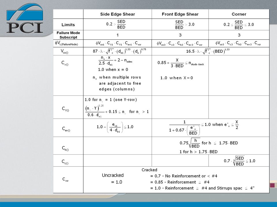
Front Edge Shear Strength, Vc3

55
Corner Edge Shear Strength, Modified Vc3

56
Side Edge Shear Strength, Vc1

58
Front Edge Shear Strength
Where Vco3 = Concrete breakout strength, single anchor Cx3 =X spacing coefficient Ch3 = Member thickness coefficient Cev3 = Eccentric shear force coefficient Cvcr = Member cracking coefficient This condition represents a majority of shear loaded connections. The shear force is applied perpendicular to the front edge de3 Notice all factors have a subscript 3 to indicate the Front Edge failure mode Vco3 is unaffected by connection or member geometry (lbs) Cx3 =X spacing coefficient for overall X spacing of a connection with two or more X rows for a de3 type anchorage
 Cx3 =X spacing coefficient for overall X spacing of a connection with two or more X rows for a de3 type anchorage.")
59
Single Anchor Strength
Where: λ = lightweight concrete factor BED = distance from back row of studs to front edge

60
X Spacing factor Where: X = Overall, out-to-out dimension of outermost
studs in back row of anchorage nstuds-back= Number of studs in back row

61
Thickness Factor Where: h = Member thickness

62
Eccentricity Factor Where
e′v = Eccentricity of shear force on a group of anchors distance between point of shear force application and geometric centroid of group of anchors

63
Cracked Concrete Factor
Uncracked concrete Cvcr = 1.0 For cracked concrete, Cvcr = 0.70 no reinforcement or reinforcement < No. 4 bar = 0.85 reinforcement ≥ No. 4 bar = 1.0 reinforcement. ≥ No. 4 bar and confined within stirrups with a spacing ≤ 4 in.

64
Corner Shear Strength A corner condition should be considered when:
where the Side Edge distance (SED) as shown The corner is considered to be a special case of the front edge loaded anchorage. If the shear force is applied perpendicular to the front edge, and the anchorage is located close to the corner, a different concrete breakout mode occurs
 as. shown. The corner is considered to be a special case of the front edge loaded anchorage. If the shear force is applied perpendicular to the front edge, and the anchorage is located close to the corner, a different concrete breakout mode occurs.")
65
Corner Shear Strength Where: Ch3 = Member thickness coefficient
Cev3 = Eccentric shear coefficient Cvcr = Member cracking coefficient Cc3 = Corner influence coefficient Note the 3 still indicated loading toward to the de3 edge for a edge 3 failure mode Note that there is no Cx3 factor when computing a corner capacity.

66
Corner factor For the special case of a large X-spacing stud anchorage located near a corner, such that SED/BED > 3, a corner failure may still result, if de1 ≤ 2.5BED

67
Side Edge Shear Strength
In this case, the shear force is applied parallel to the side edge, de1 Research determined that the corner influence can be quite large, especially in thin panels If the above ratio is close to the 0.2 value, it is recommended that a corner breakout condition be investigated, as it may still control for large BED values A connection loaded in shear parallel to a side edge results in a concrete breakout failure that does not affect the front edge. All failure mode is to the edge.

68
Side Edge Shear Strength
Where: Vco1 = nominal concrete breakout strength for a single stud CX1 = X spacing coefficient CY1 = Y spacing coefficient Cev1 = Eccentric shear coefficient Note the 1 subscript failure mode

69
Single Anchor Strength
Where: de1 = Distance from side stud to side edge (in.) do = Stud diameter (in.)
 do = Stud diameter (in.)")
70
X Spacing Factor Where: nx = Number of X-rows
x = Individual X-row spacing (in.) nsides =Number of edges or sides that influence the X direction nsides Factor = 1 or 2, I.E. 2 for a column in which connection is placed equidistant from each side
 nsides =Number of edges or sides that influence the X direction. nsides Factor = 1 or 2, I.E. 2 for a column in which connection is placed equidistant from each side.")
71
X Spacing Factor For all multiple Y-row anchorages located adjacent to two parallel edges, such as a column corbel connection, the X-spacing for two or more studs in the row: Cx1 = nx

72
Y Spacing Factor Where: ny = Number of Y-rows
Y = Out-to-out Y-row spacing (in) = Sy (in)
 = Sy (in)")
73
Eccentricity Factor Where:
ev1 = Eccentricity form shear load to anchorage centroid

74
Back Edge Shear Strength
Under a condition of pure shear the back edge has been found through testing to have no influence on the group capacity Proper concrete clear cover from the studs to the edge must be maintained

75
“In the Field” Shear Strength
When a headed stud anchorage is sufficiently away from all edges, termed “in-the-field” of the member, the anchorage strength will normally be governed by the steel strength Pry-out failure is a concrete breakout failure that may occur when short, stocky studs are used

76
“In the Field” Shear Strength
For hef/de ≤ 4.5 (in normal weight concrete) Where: Vcp = nominal pry-out shear strength (lbs)
 Where: Vcp = nominal pry-out shear strength (lbs)")
77
Front Edge Failure Example
Given: Plate with headed studs as shown, placed in a position where cracking is unlikely. The 8 in. thick panel has a 28-day concrete strength of 5000 psi. The plate is loaded with an eccentricity of 1 ½ in from the centerline. The panel has #5 confinement bars. Example Page 6-21

78
Example Problem: Determine the design shear strength of the stud group.

79
Solution Steps Step 1 – Check corner condition
Step 2 – Calculate steel capacity Step 3 – Front Edge Shear Strength Step 4 – Calculate shear capacity coefficients Step 5 – Calculate shear capacity

80
Step 1 – Check Corner Condition
Not a Corner Condition

81
Step 2 – Calculate Steel Capacity
fVns = f·ns·An·fut = 0.65(4)(0.20)(65) = 33.8 kips
(0.20)(65) = 33.8 kips.")
82
Step 3 – Front Edge Shear Strength

83
Step 4 – Shear Capacity Coefficient
Concrete Breakout Strength, Vco3

84
Step 4 – Shear Capacity Coefficient
X Spacing Coefficient, Cx3

85
Step 4 – Shear Capacity Coefficient
Member Thickness Coefficient, Ch3

86
Step 4 – Shear Capacity Coefficient
Eccentric Shear Force Coefficient, Cev3

87
Step 4 – Shear Capacity Coefficient
Member Cracking Coefficient, Cvcr Assume uncracked region of member #5 Perimeter Steel

88
Step 5 – Shear Design Strength
fVcs = f·Vco3·Cx3·Ch3·Cev3·Cvcr = 0.75(47.0)(0.93)(0.53)(0.94)(1.0) = 16.3 kips
(0.93)(0.53)(0.94)(1.0) = 16.3 kips.")
89
Interaction Trilinear Solution Unity curve with a 5/3 exponent

90
Interaction Curves

91
Combined Loading Example
Given: A ½ in thick plate with headed studs for attachment of a steel bracket to a column as shown at the right Problem: Determine if the studs are adequate for the connection

92
Example Parameters f′c = 6000 psi normal weight concrete λ = 1.0
(8) – 1/2 in diameter studs Ase = 0.20 in.2 Nominal stud length = 6 in. fut = 65,000 psi (Table ) Vu = 25 kips Nu = 4 kips Column size: 18 in. x 18 in.
 – 1/2 in diameter studs. Ase = 0.20 in.2. Nominal stud length = 6 in. fut = 65,000 psi (Table ) Vu = 25 kips. Nu = 4 kips. Column size: 18 in. x 18 in.")
93
Provide ties around vertical bars in the column to ensure confinement: f = 0.75
Determine effective depth hef = L + tpl – ths – 1/8 in = – – = 6.06 in

94
Solution Steps Step 1 – Determine applied loads
Step 2 – Determine tension design strength Step 3 – Determine shear design strength Step 4 – Interaction Equation

95
Step 1 – Determine applied loads
Determine net Tension on Tension Stud Group Determine net Shear on Shear Stud Group The eccentric shear force, Vu, is resolved by the force couple shown in the sketch at the right, assuming that the tensile force is resisted by the top two rows of studs, with breakout planes as shown. Note: assumptions for load distribution are a matter of engineering judgment

96
Step 2 – Concrete Tension Capacity

97
Step 2 – Steel Tension Capacity

98
Step 2 – Governing Tension

99
Step 3 – Concrete Shear Capacity
For concrete shear strength, it is apparent that “side edge” breakout will be critical:

100
Step 3 – Steel Shear Capacity
For concrete shear strength, it is apparent that “side edge” breakout will be critical:

101
Step 3 – Governing Shear

102
Step 4 – Interaction Check if Interaction is required

103
Step 4 – Interaction

104
Questions?

Similar presentations


>")


>")


: A rectangular beam has the dimensions shown in Figure 4.12.a and is loaded with a 40 ton concentrated.>")