Download presentation
Presentation is loading. Please wait.

1
Chapter 4 Transformer Connections
Voltage Transformation · Three-Phase Circuits · Delta Connections · Wye Connections · Delta-to-Wye Connections · Wye-to-Wye Connections · Wye-to-Delta Connections · Delta-to-Delta Connections · Open Delta Connections · Delta Connection with High Leg to Ground · Three-Phase Transformer Polarity

2
The low‑voltage winding of a standard distribution transformer connected to a single-phase circuit is normally made with two equal coils. These sections are arranged so that they may be connected in series or parallel. The low-voltage winding of a standard distribution transformer connected to a single-phase circuit is normally made with two equal coils. These coils are arranged so that they may be connected in series or parallel. This arrangement permits current to be delivered at two voltages, one twice the other. See Figure 4-1.

3
Transformer polarity may be subtractive or additive.
Regardless of which winding is the primary, the voltage‑vector relationship is best understood by considering the induced voltages in the high-voltage and low-voltage windings. Because the induced voltages in both coils are induced by the same flux, the induced voltages must be in the same direction in both windings. Assuming that the induced voltage in the high-voltage winding (H1-H2) is in the same direction as the order of lettering of the leads (H1‑H2), the induced voltage in the low‑voltage winding is from X1 to X2. See Figure 4-2.
 is in the same direction as the order of lettering of the leads (H1‑H2), the induced voltage in the low‑voltage winding is from X1 to X2. See Figure 4-2.")
4
The polarity of a transformer may be determined using a known transformer or with AC voltage.
The polarity of a transformer may be checked by comparison against a transformer of known polarity and correct lead marking, and that has the same ratio as the one to be tested. The polarity is checked by connecting the high-voltage windings of both transformers in parallel. This is done by connecting the H1 and H2 leads. If the leads of the transformer to be tested are not marked, it is assumed that similarly located high-voltage leads on the two transformers are the same. The left‑hand low‑voltage leads (facing the low-voltage side) of both transformers are connected, leaving the right-hand side leads free. See Figure 4-3.
 of both transformers are connected, leaving the right-hand side leads free. See Figure 4-3.")
5
A delta connection has the wires from the ends of each coil connected end-to-end to form a closed loop. A delta connection is a 3-phase connection method that has the wire from the ends of each coil connected end-to-end to form a closed loop. A delta connection is developed when the three coils are connected in a 3-coil closed circuit and a line lead is connected at each of the three junction points. A delta connection is often drawn as a symbol diagram with the coils in a triangular shape that resembles the Greek letter delta (∆). See Figure 4-4.
. See Figure 4-4.")
6
Studying the current in a delta-connected system at both 0° and 90° illustrates the current flow in a delta-connected system. Studying the current in a delta-connected system at both 0° and 90° illustrates the current flow in a delta-connected system. See Figure 4-5. At 0° with phases A and C at the same potential, there is no current flow between the two points, so these two coils in series have no current. The –5 A on phase A travels through the two coils in series connected to phases A and B. The –5 A on phase C travels through the two coils in series connected to phases C and B.

7
A wye connection has one end of each coil connected together and the other end of each coil left open for external connections. A wye connection is a 3-phase connection that has one end of each coil connected together and the other end of each coil left open for external connections. A wye (Y) system is also known as a star system. See Figure 4-6.
 system is also known as a star system. See Figure 4-6.")
8
Studying the current in a wye-connected system at both 0° and 90° illustrates the current flow in a wye-connected system. In a 3-phase, wye-connected system, the current in the line is the same as the current in the coil (phase) windings. This is because the current in a series circuit is the same throughout all parts of the circuit. In a balanced circuit, there is no current flow in the neutral wire because the sum of all the currents is zero. See Figure 4-7.
 windings. This is because the current in a series circuit is the same throughout all parts of the circuit. In a balanced circuit, there is no current flow in the neutral wire because the sum of all the currents is zero. See Figure 4-7.")
9
A 3-phase delta-to-wye connection is often used for distribution where a four-wire secondary distribution circuit is required. A 3-phase delta-to-wye connection is often used for distribution where a four-wire secondary distribution circuit is required. The delta-connected primary permits single-phase loads to be connected between the secondary neutral and the 3-phase line leads. The 3-phase wye voltage is 1.73 times the single-phase (line‑to‑neutral) voltage. See Figure 4-8.
 voltage. See Figure 4-8.")
10
Three single-phase transformers may be connected in a wye-to-wye connection to form a 3-phase transformer. Three single-phase transformers may be connected in a wye-to-wye connection to form a 3-phase transformer. See Figure 4-9. The 3-phase voltages on the primary and secondary sides are 4160 V and 480 V, respectively, if the single-phase voltage rating of each transformer is 2400 V and 277 V. The voltage from any line lead to the neutral wire is 2400 V on the primary side and 277 V on the secondary side.

11
A wye-to-delta connection permits single-phase and 3-phase loads to be drawn simultaneously from the delta-connected secondary at the same voltage. A wye-to-delta connection may be made with three single-phase transformers. See Figure Assuming that only a single-phase load is connected across one of the phases, the maximum load that can be obtained without overloading any part of the circuit is 150% of the maximum rating of the single-phase transformer.

12
In a wye-to-delta connection of three single-phase transformers, one unit may be disconnected from the circuit and service maintained with the secondary operating in open delta connection at 57.7% of normal bank capacity. In a wye-to-delta connection of three single-phase transformers, one unit may be disconnected from the circuit and service maintained with the secondary operating in an open delta connection at 57.7% of normal bank capacity. The neutral on the primary side and the neutral of the supply source for the primary must be grounded. See Figure The system is unbalanced and considerable telephone interference may result from such a connection.

13
In a delta-to-delta connection, the voltage of each transformer is equal to the 3-phase line voltage and the current in each of the transformers is only 57.7% of the line current. Delta-to-delta connections are used in industry where old equipment is used on new high-voltage 480 V bus duct systems. Often, when equipment arrives at its final destination, the installer discovers single-voltage motors and controls rated for 240 V. This may require a drop in supply voltage to the machine if connections cannot be made to change the controls and motors to the higher voltage. Three single-phase units wired in a delta-to-delta connection can provide power for this circuit. Three single-phase units are often used because they are more common than a 3-phase unit. See Figure 4-12.

14
Grounding one of the midpoints of the windings provides 240 V/120 V, single-phase, 3-wire service for lighting applications. The midpoint of one of the windings may be grounded for 120 V/240 V, single-phase, 3-wire service in a center-grounded delta for lighting, if the secondary is wound in two sections. See Figure Occasionally, the single-phase unit that is used for the lighting load is made larger than the other two units so that the maximum kilovolt-amps available in the other two units for 3-phase loading may be used.

15
An open delta connection makes 3-phase power available anywhere along the distribution line with the use of only two transformers rather than the usual three. An open delta connection makes 3-phase power available anywhere along the distribution line with the use of only two transformers rather than the usual three. See Figure An open delta connection may be called a V-connection because only two sides of the delta triangle are included. An open delta connection may also be called a V-V connection, since the delta is open on the primary and secondary sides of the transformers.

16
A delta connection with a high leg to ground provides 240 V, 3-phase power to equipment and 120 V power for lighting and receptacles. A delta connection with high leg to ground has a center tap grounded on one of the transformers and provides 240 V, 3-phase power to equipment and 120 V power for lighting and receptacles on two phases to the neutral, which is grounded. See Figure Phase B and phase C each provide the user 120 V to ground.

17
The phase sequence on the secondary of a three-phase transformer is the same as the phase sequence on the primary. The three high-voltage leads and the three low-voltage leads which connect to the full-phase windings are marked H1, H2, H3, and X1, X2, and X3, respectively. The markings are applied so that, with the phase sequence of voltage on the high-voltage side in the time order H1, H2, H3, the time order on the low-voltage side is X1, X2, X3. See Figure 4-16.

18
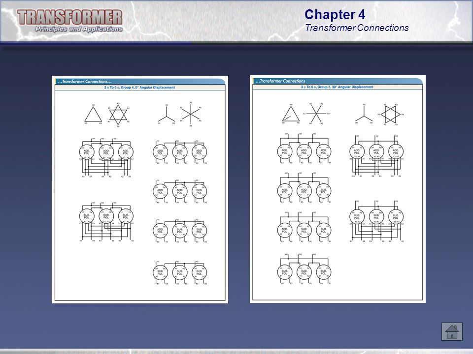
Transformers are classified into connection groups according to their phase shift.
Wye-to-delta connected transformers, with properly marked leads, always have an angular-phase displacement of 30°. For this reason, all 3-phase to 3-phase connections can be grouped in one of five different groups having an angular-phase displacement of 0°, 30°, or 180°. See Figure The vector diagram of 3-phase transformers for 3-phase to 3-phase operation is normally included by the manufacturer in the markings on the nameplate or diagram of connections which forms part of the transformer.

Similar presentations


>")

 Loops Stacey Mighty Malcolm Distribution.>")


 and Delta ( ) resistor network.>")

