Download presentation
Presentation is loading. Please wait.

1
1) Importing an IDF file with CircuitWorks
 Importing an IDF file with CircuitWorks")
3
CircuitWorks adds a Menu and Toolbar into SolidWorks

4
CircuitWorks adds a Menu and Toolbar into SolidWorks
CircuitWorks Menu CircuitWorks adds a Menu and Toolbar into SolidWorks

5
CircuitWorks Menu CircuitWorks Toolbar

6
To process an IDF or PADS file, click the ‘Open IDF File’
icon or select ‘Open IDF File…’ from the menu

7
To process an IDF or PADS file, click the ‘Open IDF File’
Open IDF File icon To process an IDF or PADS file, click the ‘Open IDF File’ icon or select ‘Open IDF File…’ from the menu

9
CircuitWorks will start, briefly displaying
licence and version information

11
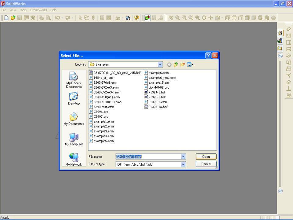
Browse to an IDF or PADS file and click open to continue

12
CircuitWorks’ Import Wizard guides the
user through importing an IDF file. The first stage is to select board cut-outs

13
CircuitWorks shows a preview of the board and its cut-outs
CircuitWorks’ Import Wizard guides the user through importing an IDF file. The first stage is to select board cut-outs

14
CircuitWorks’ Import Wizard guides the
Un-checking the boxes removes the cut-outs. Checking the boxes adds the cut-outs as required CircuitWorks’ Import Wizard guides the user through importing an IDF file. The first stage is to select board cut-outs

15
These controls allow the user to zoom in or out of the preview image
CircuitWorks’ Import Wizard guides the user through importing an IDF file. The first stage is to select board cut-outs

16
When the cut-outs have been selected, clicking ‘Next’ continues to the next stage of the Import Wizard

17
The next stage shows how many
non-plated holes there are in the IDF file

18
The total number of non-plated holes found is shown here
The next stage shows how many non-plated holes there are in the IDF file

19
The total number of non-plated holes found is shown here
Holes in the IDF file are either associated with the board or with the components The total number of non-plated holes found is shown here The next stage shows how many non-plated holes there are in the IDF file

20
The next stage shows how many
Holes in the IDF file are either associated with the board or with the components Checking this option creates the non-plated holes associated with the board The next stage shows how many non-plated holes there are in the IDF file

21
Holes in the IDF file are either associated with the board or with the components Checking this option creates the non-plated holes associated with the components on the board

22
CircuitWorks displays the minimum and maximum diameters found for each hole type

23
By checking this option and editing the size range
By checking this option and editing the size range. CircuitWorks can be configured to only create board non-plated holes within a certain range of diameters

24
In the same way, this option configures CircuitWorks to only create component non-plated holes within the specified range of diameters

25
Checking this option will only include non-plated holes in the SolidWorks assembly that are associated with certain components

26
The user can select which components holes in include in the assembly from the pull-down list

27
In this example, only the non-plated holes associated with components PL7 and TR8 will be added to the board part in SolidWorks

28
When the non-plated hole options have been set, clicking ‘Next’ continues to the next stage

29
The next stage of the Wizard shows how
many plated holes are in the IDF file

30
The next stage of the Wizard shows how
Plated holes are the conductive holes in the board which can be associated either with the board or the components The next stage of the Wizard shows how many plated holes are in the IDF file

31
392 Plated holes found in the IDF file
The next stage of the Wizard shows how many plated holes are in the IDF file

32
392 Plated holes found in the IDF file
None of the holes are associated with the board The next stage of the Wizard shows how many plated holes are in the IDF file

33
None of the holes are associated with the board
All 392 holes are associated with the components on the board The next stage of the Wizard shows how many plated holes are in the IDF file

34
All 392 holes are associated with the components on the board
Plated holes can be filtered by size or component in the same way as the non-plated holes in the previous stage

35
When the plated hole options have been set, clicking ‘Next’ continues to the next stage

36
The ‘Component Heights’ page of the Import
Wizard allows the user to edit the heights of the components in the IDF file if required

37
Green icons indicate components in the IDF file with a non-zero height
The ‘Component Heights’ page of the Import Wizard allows the user to edit the heights of the components in the IDF file if required

38
Red icons indicate components in the IDF file with zero height
The ‘Component Heights’ page of the Import Wizard allows the user to edit the heights of the components in the IDF file if required

39
Expanding the icon shows the current height and units
Expanding the icon shows the current height and units. Here the component height is 0 Thou

40
A new height can be defined for the component: 30 Thou in this example.

41
Display options allow the user to view the components by name or part number

42
Powerful search controls allow the user to locate a particular component easily

43
When any heights have be changed as required, clicking ‘Next’ continues to the next stage of the Import Wizard

44
The ‘Component Filters’ page of the Import Wizard
allows the user to set criteria to include or exclude components from the final SolidWorks assembly

45
The ‘Component Filters’ page of the Import Wizard
Components can be Filtered out of the SolidWorks assembly in a number of ways The ‘Component Filters’ page of the Import Wizard allows the user to set criteria to include or exclude components from the final SolidWorks assembly

46
Components can be filtered by their name
Filtered out of the SolidWorks assembly in a number of ways Components can be filtered by their name The ‘Component Filters’ page of the Import Wizard allows the user to set criteria to include or exclude components from the final SolidWorks assembly

47
Components can be filtered by their name
Filtered out of the SolidWorks assembly in a number of ways Components can be filtered by their name The ‘Component Filters’ page of the Import Wizard allows the user to set criteria to include or exclude components from the final SolidWorks assembly

48
The ‘Component Filters’ page of the Import Wizard
Components can be Filtered out of the SolidWorks assembly in a number of ways Lists of components to include or exclude in the SolidWorks assembly can be added with full support for wildcard characters The ‘Component Filters’ page of the Import Wizard allows the user to set criteria to include or exclude components from the final SolidWorks assembly

49
Commonly used filter settings can be saved to be used again in future
Components can be Filtered out of the SolidWorks assembly in a number of ways Commonly used filter settings can be saved to be used again in future The ‘Component Filters’ page of the Import Wizard allows the user to set criteria to include or exclude components from the final SolidWorks assembly

50
Components can also be filtered from the assembly by their height
Components can be Filtered out of the SolidWorks assembly in a number of ways Components can also be filtered from the assembly by their height

51
Components can also be filtered from the assembly by their height
Components can be Filtered out of the SolidWorks assembly in a number of ways Components can also be filtered from the assembly by their height

52
Components can be filtered by the side of the board they are on
Filtered out of the SolidWorks assembly in a number of ways Components can be filtered by the side of the board they are on

53
When any filters have been set as required, clicking ‘Next’ continues to the next stage of the Import Wizard

54
CircuitWorks is now ready to start building the board in
SolidWorks. The dialog lists summary information about the IDF file, such as its source and creation date

55
Click ‘Build’ to start the build process
CircuitWorks is now ready to start building the board in SolidWorks. The dialog lists summary information about the IDF file, such as its source and creation date

56
CircuitWorks will now build the board model in SolidWorks
adding features for the different hole types if required

57
CircuitWorks will now build the board model in SolidWorks
A progress bar indicates how far CircuitWorks is through the build process CircuitWorks will now build the board model in SolidWorks adding features for the different hole types if required

58
A progress bar indicates how far CircuitWorks is through the build process
The user can stop the build process at any time. CircuitWorks can even continue processing an incomplete board from when it was interrupted

59
CircuitWorks prompts the user when board processing
is complete. The user can view the information generated during the build process

60
Icons indicate CircuitWorks progress adding components to the board
CircuitWorks prompts the user when board processing is complete. The user can view the information generated during the build process

61
Icons indicate CircuitWorks progress adding components to the board
Clicking ‘OK’ closes the window

62
CircuitWorks has created an assembly of the board and
components in SolidWorks

63
CircuitWorks has created an assembly of the board and
Any components not already existing in CircuitWorks’ component library have been created and named automatically CircuitWorks has created an assembly of the board and components in SolidWorks

64
For more information or to download an evaluation copy of CircuitWorks, visit or

Similar presentations


 Exporting an IDF file with CircuitWorks>")


 CircuitWorks Component Library>")


 follow the hyperlinks to navigate to the specified Topic or Figure.>")


