Download presentation
Presentation is loading. Please wait.

1
An improved SVD-based watermarking scheme using human visual characteristics Chih-Chin Lai Department of Electrical Engineering, National University of Kaohsiung, Kaohsiung 81148, Taiwan IEEE TRANSACTIONS ON KNOWLEDGE AND DATA ENGINEERING, VOL. 23, NO. 3, MARCH 2011

2
OUTLINE INTRODUCTION BACKGROUND ◦ Discrete cosine transform ◦ Singular value decomposition THE PROPOSED WATERMARKING SCHEME ◦ Image information ◦ The watermark embedding procedure EXPERIMENTAL RESULTS CONCLUSION

3
INTRODUCTION Digital watermarking has been regarded as an effective solution to protect the copyright of digital media. In this paper, an improved SVD-based watermarking technique considering human visual characteristics is presented. Experimental results are provided to demonstrate the proposed approach is able to withstand a variety of image processing attacks.

4
BACKGROUND Discrete cosine transform (1) (2) defined as
 (2) defined as")
5
BACKGROUND Discrete cosine transform

6
BACKGROUND

7
BACKGROUND

8
BACKGROUND

9
BACKGROUND Singular value decomposition (3)
")
10
BACKGROUND Singular value decomposition

11
THE PROPOSED WATERMARKING SCHEME Image information In designing a watermarking scheme, two conflicting requirements should be satisfied at the same time: ◦ (1) the watermark should be imperceptible ◦ (2) the watermark should be robust and very difficult to remove. Using HVS properties to produce a more robust watermark.

12
Image information The HVS model can be used not only tomeasure the perceptibility ofwatermarks once they are embedded, but also to control that perceptibility during the embedding process. Therefore, we considered the visual entropy and edge entropy,which are also used by in order to select watermark embedding regions that satisfy the aforementioned two requirements. THE PROPOSED WATERMARKING SCHEME

13
Visual entropy Edge entropy (4) (5)
 (5)")
14
Visual entropy THE PROPOSED WATERMARKING SCHEME

15
The watermark embedding procedure THE PROPOSED WATERMARKING SCHEME

16
The watermark embedding procedure ◦ Step 1. The cover image is first partitioned into non-overlapping blocks with 8×8 pixels. ◦ Step 2. Select appropriate blocks forwatermark embedding by utilizing the HVS characteristics. ◦ Step 3. Apply DCT technique to the selected blocks and then obtain DCT domain frequency bands. ◦ Step 4. Apply SVD to all DCT transformed blocks. THE PROPOSED WATERMARKING SCHEME

17
The watermark embedding procedure step5 ◦ On each selected block, the relationship between the entries in the first column of the U matrix is examined. ◦ The watermark is embedded by changing the relation between the third (u3,1) and the fourth (u4, 1) entries in the first column. ◦ If the embedded binarywatermark bit is 1, then the value of (u3, 1−u4, 1) should be positive and its magnitude is greater than a threshold (T). ◦ If the embedded binary watermark bit is 0, then the value of THE PROPOSED WATERMARKING SCHEME
 and the fourth (u4, 1) entries in the first column. ◦ If the embedded binarywatermark bit is 1, then the value of (u3, 1−u4, 1) should be positive and its magnitude is greater than a threshold (T). ◦ If the embedded binary watermark bit is 0, then the value of THE PROPOSED WATERMARKING SCHEME.")
18
The watermark embedding procedure step5 ◦ (u3,1−u4,1) should be negative and its magnitude is greater than a threshold (T). ◦ When these two conditions are violated,the entries of u3, 1 and u4,1 should be modified as ˆu3;1 and ˆu4;1,respectively, based on the following rules: THE PROPOSED WATERMARKING SCHEME (6) (7)
 (7).")
19
The watermark extracting procedure THE PROPOSED WATERMARKING SCHEME

20
The watermark extracting procedure ◦ Step 1. Thewatermarked image is first partitioned into blockswith 8×8 pixels. ◦ Step 2. The visual entropy and edge entropy of each block are calculated to determine the block where the watermark is embedded. ◦ Step 3. Apply DCT to the selected blocks to obtain DCT domain frequency. ◦ Step 4. Apply SVD to all DCT transformed blocks. THE PROPOSED WATERMARKING SCHEME

21
The watermark extracting procedure Step 5. ◦ The relationship between the third and the fourth entries in the first column of the U matrix is examined. ◦ If a positive difference is detected, then the extracted watermark bit is a 1, whereas a negative difference would imply that a watermark bit 0 is extracted. ◦ These extracted bit values are used to construct the extracted watermark. THE PROPOSED WATERMARKING SCHEME

22
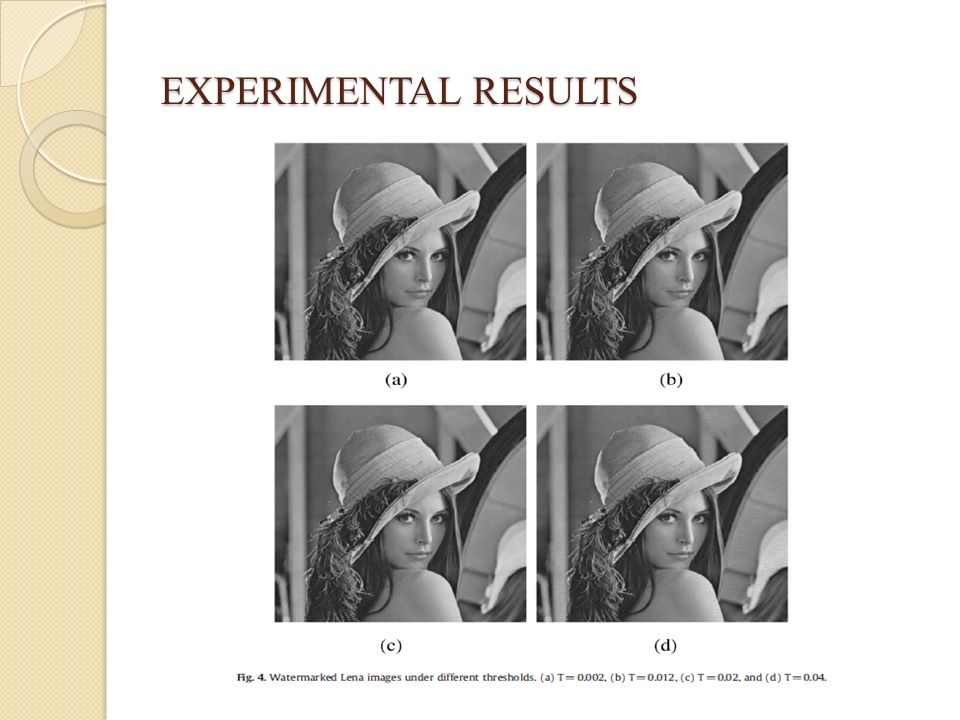
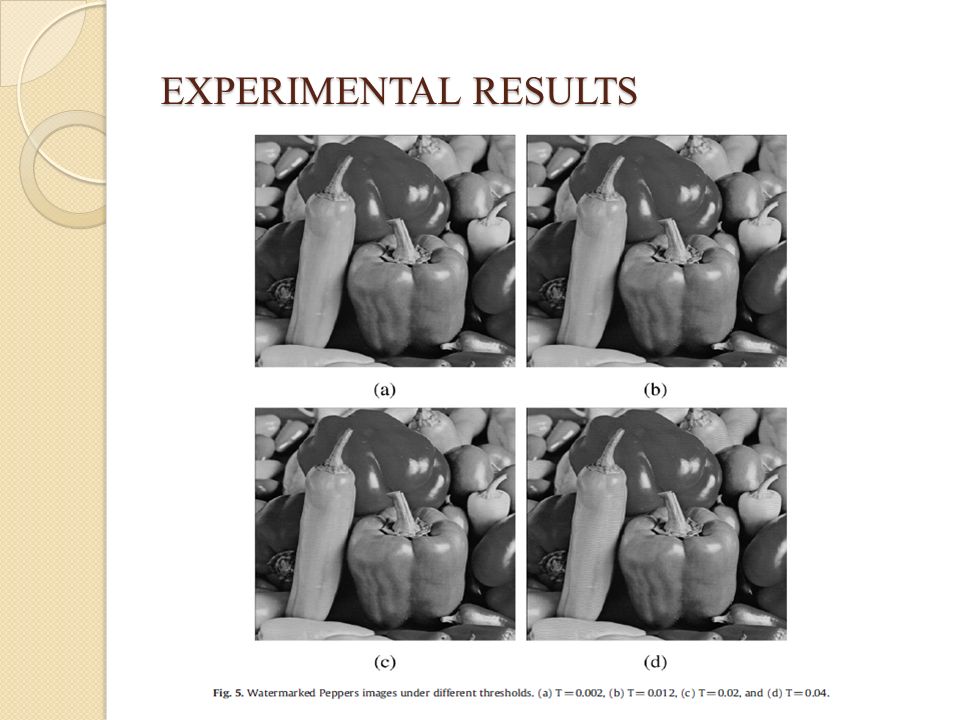
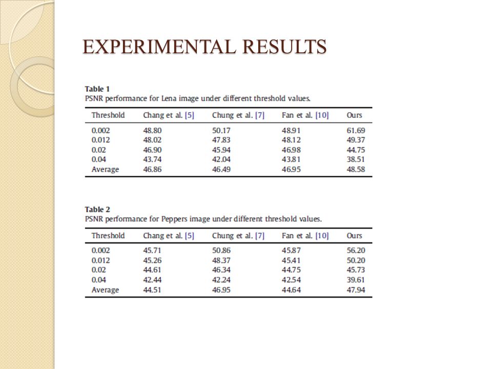
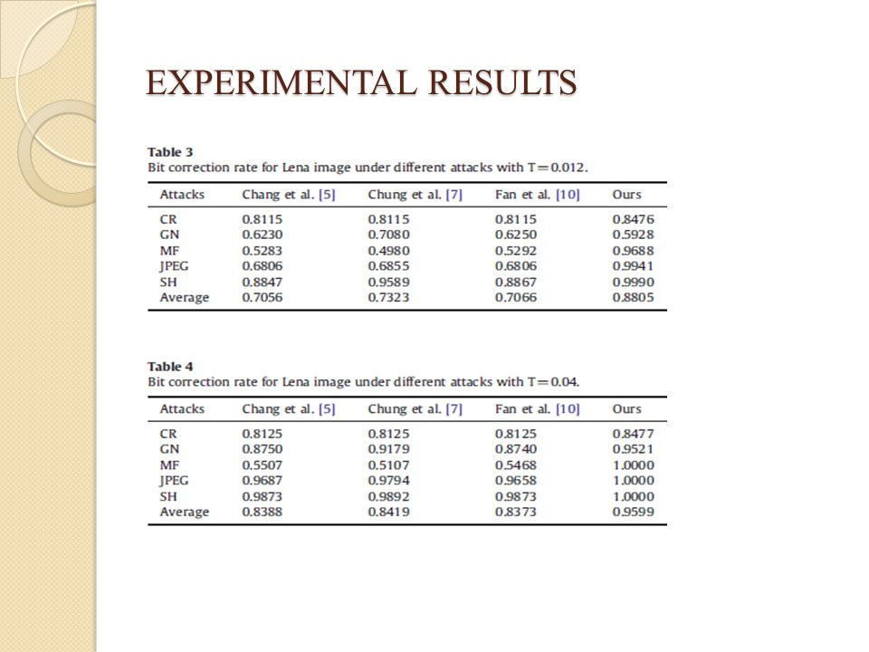
EXPERIMENTAL RESULTS

28
Fig. 6. Extracted watermarks at the threshold value=0.012 with different attacks. (a) Cropping, (b) Gaussian noise, (c) Median filtering, (d) JPEG compression, and (e) Sharpening. Fig. 7. Extracted watermarks at the threshold value=0.04 with different attacks. (a) Cropping, (b) Gaussian noise, (c) Median filtering, (d) JPEG compression, and (e) Sharpening.
 Cropping, (b) Gaussian noise, (c) Median filtering, (d) JPEG compression, and (e) Sharpening. Fig. 7. Extracted watermarks at the threshold value=0.04 with different attacks. (a) Cropping, (b) Gaussian noise, (c) Median filtering, (d) JPEG compression, and (e) Sharpening..")
29
CONCLUSION The technique fully exploits the respective feature of SVD which efficiently represents intrinsic algebraic properties of an image. The use of HVS characteristics helps to select watermark embedding regions for a good compromise between robustness and quality of the watermarked image.

Similar presentations


>")


 Established –Watermarking (1990s) Non-reversible.>")


