Download presentation
Presentation is loading. Please wait.

1
Energised by two quantities(voltage and current) Φ1 and Φ2 set by voltage and current Eddy currents induced in the disc due to two fluxes Interaction b/n Φ1 and Φ2 produce a torque T proportional to VIcosΦ Power factor increases by compensating winding and shading coil θ between I₁ and I₂ is equal to (90-Φ) INDUCTION DISC TYPE DIRECTIONAL RELAY
 Φ1 and Φ2 set by voltage and current Eddy currents induced in the disc due to two fluxes Interaction b/n Φ1 and Φ2 produce a torque T proportional to VIcosΦ Power factor increases by compensating winding and shading coil θ between I₁ and I₂ is equal to (90-Φ) INDUCTION DISC TYPE DIRECTIONAL RELAY")
2
T = I₁ I₂sin (90-Φ)α I₁ I₂ cos Φ α VI cos Φ In induction cup two opposite poles energised by voltage, another two poles by current Φ < 90 degrees, Torque is positive,Power flow in reverse direction, relay operates Φ > 90 degrees(b/n 90-180) Torque is negative, Power flow in positive direction, relay will not operate For normal power flow the relay supplied by V and –I,Reverse power flow the relay supplied by V and I (a)Phasor diagram for directional relay (b)Connection of current coil for reverse power relay
α I₁ I₂ cos Φ α VI cos Φ In induction cup two opposite poles energised by voltage, another two poles by current Φ < 90 degrees, Torque is positive,Power flow in reverse direction, relay operates Φ > 90 degrees(b/n ) Torque is negative, Power flow in positive direction, relay will not operate For normal power flow the relay supplied by V and –I,Reverse power flow the relay supplied by V and I (a)Phasor diagram for directional relay (b)Connection of current coil for reverse power relay")
3
Which operates when current exceeds pick-up value in specific direction Contains two relaying units The secondary winding of the overcurrent unit is kept open Directional unit operates secondary winding of over current unit Overcurrent unit may be wattmetric or shaded pole type Wound coil instead of shading coil with ordinary strip

4
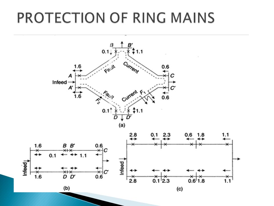
Sending end Non-directional relays(Symbol ) Receiving end Directional Relays (Symbol ) Faulty feeder is isolated and healthy feeder is maintained
 Receiving end Directional Relays (Symbol ) Faulty feeder is isolated and healthy feeder is maintained")
6
This type protection is costly and complex Each feeder requires 2 relays A non directional relay is required at one end and a directional relay is required at other end Operating time is determined by the grading

7
Earth Fault A fault which involves ground Ex: Single line- ground, LL-G Phase Fault Faults which do not involve ground Ex: Double line fault (line-line) Earth Fault Protection : The protective scheme used for the Protection of power system element against earth faults Phase Fault Protection : The protective scheme used for the Protection of power system element against phase faults Protective schemes are different
 Earth Fault Protection : The protective scheme used for the Protection of power system element against earth faults Phase Fault Protection : The protective scheme used for the Protection of power system element against phase faults Protective schemes are different")
8
Used for Protection of a section(or an element ) Phase fault relays are called overcurrent relays Operating principle and construction is same Plug setting of earth fault relay is 20% to 80% In steps of 10% Earth fault relays are more sensitive than phase fault relays. Plug setting for Phase fault relays is 50% to 200% in steps of 25% Overcurrent relays used for phase faults

9
The earth fault relay is energised by a residual current ( ia+ ib+ ic) is called residual current Normal condition residual current zero Balanced condition current through earth fault relay zero. Minimum plug setting is 20% or 30% Magnitude of earth fault current depends on fault impedance and neutral earthing Fault impedance of E. faults > phase faults Due to Earth fault current< Phase fault current Plug setting % is low for earth faults compared to phase

10
Earth fault relay C.T Burden is More than phase fault relay Because of relay is set at low % values( Impedance is high) Fig (b) and (c) used for protection of transformer and alternator Zero sequence current flows through the neutral which actuates earth fault relay Fig (d) specifies special C. T, Known as core-balance C.T

11
Three overcurent relays Scheme is against phase faults This scheme will also sense earth faults Less sensitive Two overcurent relays and one earth relays Over current relay and earth relay in series C.T burden is high and cause saturation

12
One directional overcurrent relay required Operating principle is same It contains two elements Directional element I.D.M.T element Directional element has two coils One coil Energised by current Other by voltage Current coil energised by residual current Voltage coil energised by residulal voltage

13
Neutral point is grounded through P.T Potential coil is connected to secondary of P.T I.D.M.T has plug setting 20% to 80% Directional Earth Fault Relay

Similar presentations


. The linear variable differential transducer (LVDT) is a type of electrical transformer used for measuring.>")
