Download presentation
Presentation is loading. Please wait.

1
Computer Organization and Architecture Dr. B T P Madhav Professor & CSRG Head Department of ECE, K L University

2
Introduction to computer System and its sub modules There are two basic types of electrical signals, namely, analog and digital. The analog signals are continuous in nature and digital signals are discrete in nature. The electronic device that works with continuous signals is known as analog device and the electronic device that works with discrete signals is known as digital device. We use ‘0’ to represent LOW and ‘1’ to represent HIGH. Department of ECE, K L University

3
Computer Architecture Computer architecture refers to those parameters of a computer system that are visible to a programmer or those parameters that have a direct impact on the logical execution of a program. Examples of architectural attributes include the instruction set, the number of bits used to represent different data types, I/O mechanisms, and techniques for addressing memory. Department of ECE, K L University

4
Computer Organization Computer organization refers to the operational units and their interconnections that realize the architectural specifications. Examples of organizational attributes include those hardware details transparent to the programmer, such as control signals, interfaces between the computer and peripherals, and the memory technology used. Department of ECE, K L University

5
Basic Computer Model and different units of Computer Central Processor Unit, Input Unit, Output Unit, Memory Unit Department of ECE, K L University

6
Number System & Representation Decimal Number System (0-9) Octal Number System (0-7) Hexa-Decimal Number System (0-F) Binary Number System (0, 1) Department of ECE, K L University
 Octal Number System (0-7) Hexa-Decimal Number System (0-F) Binary Number System (0, 1) Department of ECE, K L University")
7
Representation of Real Number Binary representation of 41.6875 is 101001.1011 Therefore any real number can be converted to binary number system There are two schemes to represent real number : 1)Fixed-point representation 2) Floating-point representation
Fixed-point representation 2) Floating-point representation")
8
Fixed-point representation: Binary representation of 41.6875 is 101001.1011 To store this number, we have to store two information, -- the part before decimal point and -- the part after decimal point. This is known as fixed-point representation where the position of decimal point is fixed and number of bits before and after decimal point are also predefined.

9
Floating-point representation: In this representation, numbers are represented by a mantissa comprising the significant digits and an exponent part of Radix R. The format is: Numbers are often normalized, such that the decimal point is placed to the right of the first non zero digit. For example, the decimal number, To store this number in floating point representation, we store 5236 in mantissa part and 3 in exponent part.

10
Signed Integer Range of natural numbers is 0 to 2 n -1 By including –ve numbers -2 n-1 -1 to 2 n-1 -1 If we consider 8-bit number, then range of natural number is from 0-255 For signed integer range is from -127 to 127 Department of ECE, K L University Signed Magnitude Form If MSB = 0 then it is +ve and if MSB = 1 then it is –ve

11
Representation of Signed Integer in 1’s complement form 01011100 10100011 11111111 By adding ‘1’ to the result, it is ‘0’ Representation of Signed Integer in 2’s complement form 01011100 10100100 100000000 Department of ECE, K L University

12
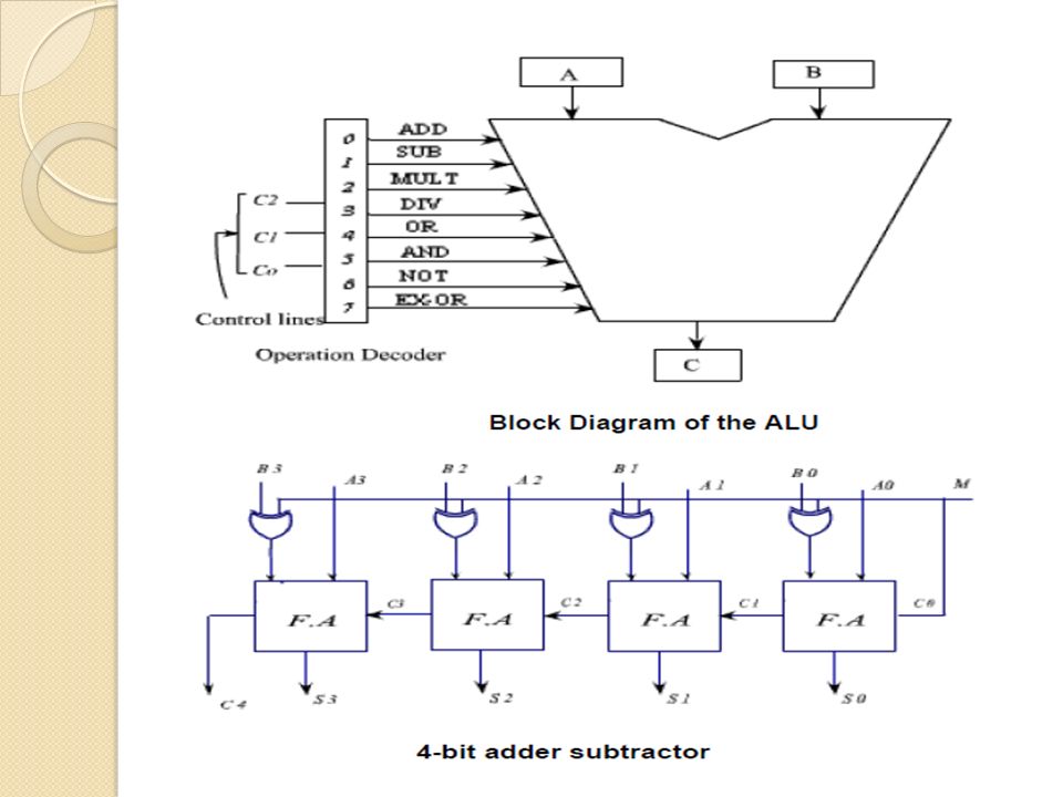
Arithmetic & Logical Unit Consider an ALU which can perform four arithmetic operations and four logical operations To distinguish between arithmetic and logical operation, we may use a signal line, 0 - in that signal, represents an arithmetic operation and 1 - in that signal, represents a logical operation. Department of ECE, K L University

14
Memory 1. Concept of Memory. 2. Cache Memory. 3. Memory Management 4. Virtual memory Department of ECE, K L University The memory of computer is broadly categories into two categories: Internal Memory or Primary Memory External Memory or Secondary Memory

15
Primary Memory RAM: Random Access Memories are volatile in nature. As soon as the computer is switched off, the contents of memory are also lost. Types: SRAM, DRAM ROM: Read only memories are non volatile in nature. The storage is permanent, but it is read only memory. We can not store new information in ROM. Types: PROM, EPROM, EEPROM, UVPROM Department of ECE, K L University

16
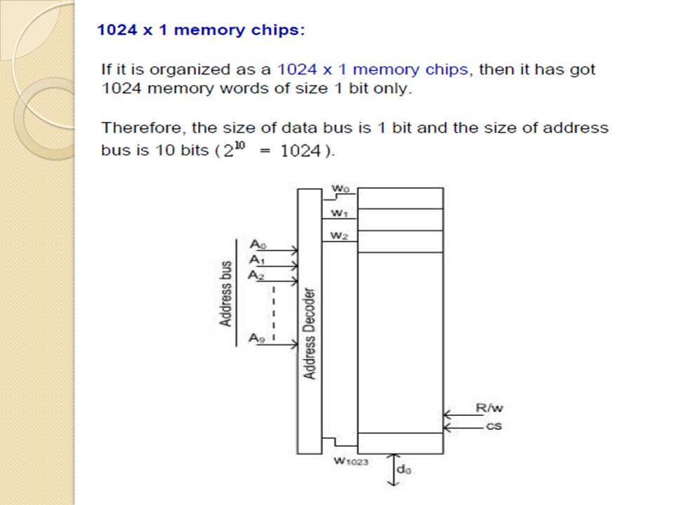
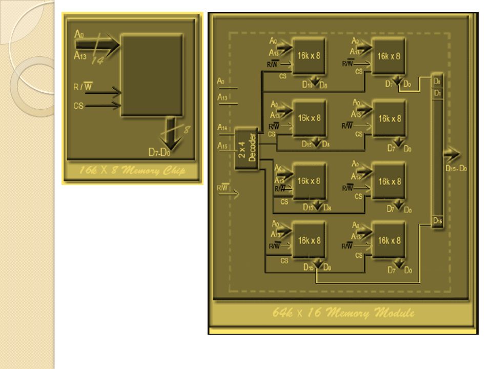
Main Memory Organization 16X4 Means 16 Locations & 4 bits in each Location Read – Retrieve data from memory to CPU registers Write – Store data to memory from CPU registers To transfer data we require data bus To specify or to identify a particular memory location we require address bus Department of ECE, K L University

17
The data transfer between main memory and the CPU takes place through two CPU registers. MAR : Memory Address Register MDR : Memory Data Register. If the MAR is k-bit long, then the total addressable memory location will be 2 k. If the MDR is n-bit long, then the n bit of data is transferred in one memory cycle.

18
Binary Storage Cell Department of ECE, K L University

19
Depending on the technology used to construct a RAM, there are two types of RAM – SRAM: Static Random Access Memory. DRAM: Dynamic Random Access Memory DRAMSRAM SRAM & DRAM both are volatile DRAM packing density is more & Less expensive DRAM requires supporting refresh circuitry SRAM is faster than DRAM

23
Cache Memory Department of ECE, K L University It is the fact that CPU is a faster device and memory is a relatively slower device. Memory access is the main bottleneck for the performance efficiency. If a faster memory device can be inserted between main memory and CPU, the efficiency can be increased. The faster memory that is inserted between CPU and Main Memory is termed as Cache memory.

24
Memory Management Department of ECE, K L University

25
In an Uni-programming system, main memory is divided into two parts : one part for the operating system and the other part for the program currently being executed. In multiprogramming system, the user part of memory is subdivided to accommodate multiple processes. The task of subdivision is carried out dynamically by the operating system and is known as memory management.

26
To utilize the idle time of CPU, some of the process must be off loaded from the memory and new process must be brought to this memory place. This is known swapping. Partitioning 1) Fixed size partitions 2) Variable size partitions
 Fixed size partitions 2) Variable size partitions.")
27
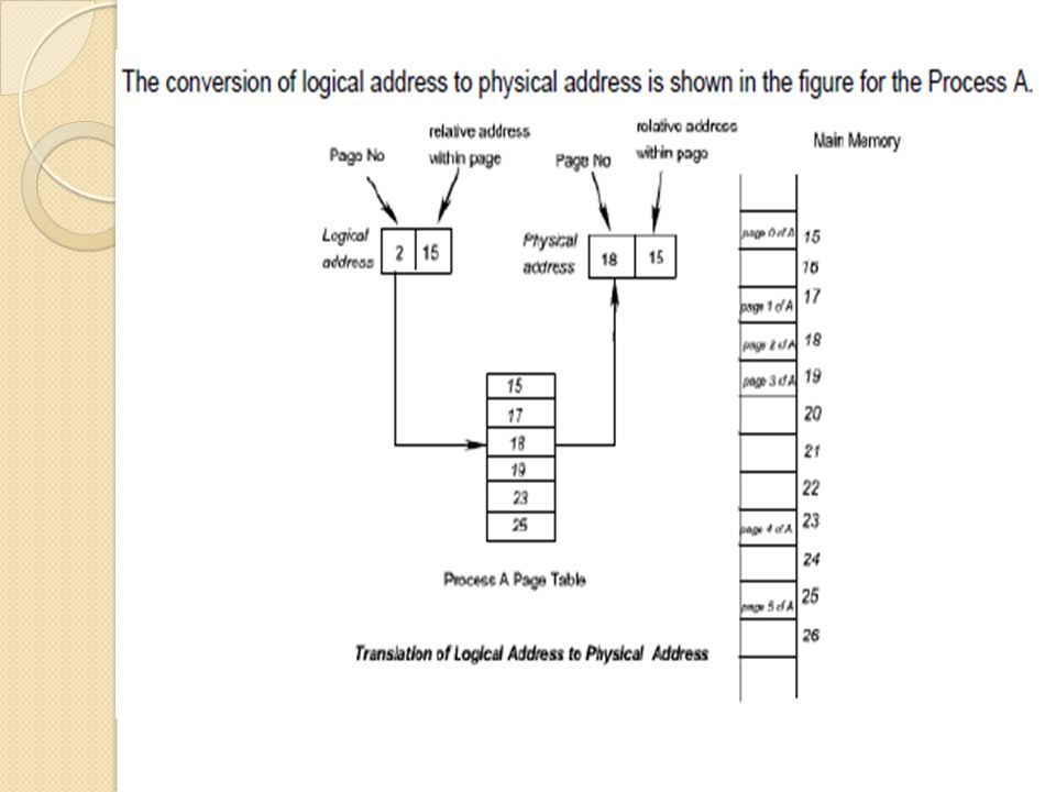
Paging Department of ECE, K L University The memory is partitioned into equal fixed size chunks that are relatively small. This chunk of memory is known as frames or page frames. Each process is also divided into small fixed chunks of same size. The chunks of a program is known as pages. At a given point of time some of the frames in memory are in use and some are free. The list of free frame is maintained by the operating system.

30
Virtual Memory Department of ECE, K L University The virtual address space is used to develop a process. The special hardware unit, called Memory Management Unit (MMU) translates virtual address to physical address. When the desired data is in the main memory, the CPU can work with these data. If the data are not in the main memory, the MMU causes the operating system to bring into the memory from the disk.
 translates virtual address to physical address. When the desired data is in the main memory, the CPU can work with these data. If the data are not in the main memory, the MMU causes the operating system to bring into the memory from the disk..")
31
Control Unit Department of ECE, K L University To generate the control signal in proper sequence, a wide variety of techniques exist. Most of these techniques, however, fall into one of the two categories, Hardwired Control : Microprogrammed Control : To execute an instruction, the control unit of the CPU must generate the required control signal in the proper sequence.

32
Hardwired Control : In this hardwired control techniques, the control signals are generated by means of hardwired circuit. The main objective of control unit is to generate the control signal in proper sequence.

33
Eg: Programmable Logic Array Department of ECE, K L University

34
Microprogrammed Control Department of ECE, K L University There is an alternative approach by which the control signals required inside the CPU can be generated. This alternative approach is known as microprogrammed control unit. In microprogrammed control unit, the logic of the control unit is specified by a microprogram. A microprogrammed control unit is a relatively simple logic circuit that is capable of (1) sequencing through microinstructions and (2) generating control signals to execute each microinstruction.
 sequencing through microinstructions and (2) generating control signals to execute each microinstruction..")
35
Control Word (CW) : Control word is defined as a word whose individual bits represent the various control signal. The individual control words in this microprogram are referred to as microinstructions. Department of ECE, K L University

36
Instruction Set The operation of a CPU is determine by the instruction it executes, referred to as machine instructions or computer instructions. The collection of different instructions is referred as the instruction set of the CPU. Each instruction must contain the information required by the CPU for execution. Department of ECE, K L University

37
It is difficult to deal with binary representation of machine instructions. Thus, it has become common practice to use a symbolic representation of machine instructions. Opcodes are represented by abbreviations, called mnemonics, that indicate the operations A simple instruction format

38
The instruction set of a CPU can be categorized as follows: 1. Data Processing: 2. Data Storage: 3. Data Movement: 4. Control: Types of Operands 1.Addresses: 2.Numbers: 3.Characters: 4.Logical Data:

39
Types of Operations Data Transfer Arithmetic Logical Conversion Input Output [ I/O ] System Control Transfer Control Department of ECE, K L University
![Types of Operations Data Transfer Arithmetic Logical Conversion Input Output [ I/O ] System Control Transfer Control Department of ECE, K L University](http://images.slideplayer.com/42/11562992/slides/slide_39.jpg "Types of Operations Data Transfer Arithmetic Logical Conversion Input Output [ I/O ] System Control Transfer Control Department of ECE, K L University")
40
A.Data Transfer Department of ECE, K L University Move (Transfer) --------Transfer word or block from source to destination Store ----------------------Transfer word from processor to memory Load (fetch) -------------Transfer word from memory to processor Exchange ----------------Swap contents of source and destination Clear (reset)------------- Transfer word of 0s to destination Set -------------------------Transfer word of 1s to destination Push -----------------------Transfer word from source to top of stack Pop -------------------------Transfer word from top of stack to destination
 Transfer word or block from source to destination Store Transfer word from processor to memory Load (fetch) Transfer word from memory to processor Exchange Swap contents of source and destination Clear (reset) Transfer word of 0s to destination Set Transfer word of 1s to destination Push Transfer word from source to top of stack Pop Transfer word from top of stack to destination")
41
B. Arithmetic Department of ECE, K L University Add --------------Compute sum of two operands Subtract --------Compute difference of two operands Multiply ---------Compute product of two operands Divide -----------Compute quotient of two operands Absolute --------Replace operand by its absolute value Negate ----------Change sign of operand Increment ------Add 1 to operand Decrement -----Subtract 1 from operand

42
Logical: Department of ECE, K L University AND -----------------------Performs the logical operation AND bitwise OR--------------------------Performs the logical operation OR bitwise NOT -----------------------Performs the logical operation NOT bitwise Exclusive OR -------------Performs the specified logical operation Exclusive-OR bitwise Test --------------------------Test specified condition; set flag(s) based on outcome Compare -------------------Make logical or arithmetic comparison Set flag(s) based on outcome Set Control Variables------Class of instructions to set controls for protection purposes, interrupt handling, timer control etc. Shift -----------------------Left (right) shift operand, introducing constant at end Rotate --------------------Left (right) shift operation, with wraparound end
 shift operand, introducing constant at end Rotate Left (right) shift operation, with wraparound end.")
43
Input/output : Department of ECE, K L University Input (Read)----- Transfer data from specified I/O port or device to destination (e.g., main memory or processor register) Output (Write)----Transfer data from specified source to I/O port or device. Start I/O------------ Transfer instructions to I/O processor to initiate I/O operation. Test I/O --------------Transfer status information from I/O system to specified destination

44
System Control: System control instructions are those which are used for system setting and it can be used only in privileged state. Typically, these instructions are reserved for the use of operating systems. Department of ECE, K L University

45
Transfer of Control: The most common transfer-of-control operations found in instruction set are: Branch Skip Procedure call. Department of ECE, K L University

46
BRP X ----Branch to location X if result is positive BRN X ---- Branch to location X if result is negative BRZ X----- Branch to location X is result is zero BRO X----- Branch to location X if overflow occurs Jump (branch) Unconditional transfer, load PC with specific address Jump conditional Test specific condition; either load PC with specific address or do nothing, based on condition Jump to subroutine Place current program control information in known location; jump to specific address Return Replace contents of PC and other register from known location Skip Increment PC to skip next instruction Skip Conditional Test specified condition; either skip or do nothing based on condition Halt Stop program execution
 Unconditional transfer, load PC with specific address Jump conditional Test specific condition; either load PC with specific address or do nothing, based on condition Jump to subroutine Place current program control information in known location; jump to specific address Return Replace contents of PC and other register from known location Skip Increment PC to skip next instruction Skip Conditional Test specified condition; either skip or do nothing based on condition Halt Stop program execution")
47
Instruction Format:

50
Design of ALU

52
Machine Language A processor can understand and execute machine instructions. Such instructions are simply binary numbers stored in the computer. If a programmer wished to program directly in machine language, then it would be necessary to enter the program as binary data. Department of ECE, K L University

53
1.Load the contents of location 201 into the AC. 2. Add the contents of location 202 to the AC. 3. Add the contents of location 203 to the AC. 4. Store the contents of the AC in location 204. N = I + J + K

54
Assembly Language Department of ECE, K L University I1: Move R3, R7 /R3 ← (R7) I2: Load R8, (R3) /R8 ← Memory (R3) I3: Add R3, R3, 4 /R3 ← (R3) + 4 I4: Load R9, (R3) /R9 ← Memory (R3) I5: BLE R8, R9, L3 /Branch if (R9) > (R8) Assembly language is a programming language that is one step away from machine language. Typically, each assembly language instruction is translated into one machine instruction by the assembler. Assembly language is hardware dependent, with a different assembly language for each type of processor

55
Compiler: It is a program which translates a high level language program into a machine language program. Interpreter: An interpreter is a program which translates statements of a program into machine code. It translates only one statement of the program at a time. Linker: In high level languages, some built in header files or libraries are stored. These libraries are predefined and these contain basic functions which are essential for executing the program. These functions are linked to the libraries by a program called Linker. Loader: Loader is a program that loads machine codes of a program into the system memory. In Computing, a loader is the part of an Operating System that is responsible for loading programs.

Similar presentations


 1 Prepared By: Associate Prof. Dr Masri Ayob.>")


