Download presentation
Presentation is loading. Please wait.

1
HAM CRAM AMATEUR RADIO TECHNICIAN LICENSE REVIEW COURSE BEST WHEN IMMEDIATELY FOLLOWED BY THE EXAM Revised for post 1 July 2010 Exams Version Revision 0, June 9, 2010 WW.W9PE.US © COPYRIGHT RF gillette inc. Unchanged Reproduction Approved

2
intentionally blank

3
Introduction To obtain your FCC Technician license you will have to pass a test covering; radio Law, operating procedures and technical knowledge. From experience we have found that most wrong answers during testing are on the law and procedures. We assume that is because most taking a cram course have developed some technical knowledge. You must know Ohm’s law algebra or memorize same from the question pool to pass the test. You must also memorize some other data from the FCC rules. Review any license manual before you come to a cram. One is; “The ARRL Ham Radio License Manual #9639”, at 1-800-326-3942 or www.arrl.org/shop. The entire question pool is in most license manuals and on the web. You can take practice exams using the Internet; www.qrz.com. Your library and community college have public access web terminals. We will cover all of the question’s material in this class.

4
Electric Units & Ohms Law l Voltage (volt) is electromotive force. l Current (amp) is electron flow. l Resistance (ohm) is the inhibitor to current. – Ohm’s law is: E (volts) = I (amps) x R (ohms). lE = I x R E / I = R E / R = I l Power (watts)=Voltage x Current = E I = W l If required some examples should be added. lBy instructor on blackboard. lBy student to verify understanding.
 is electron flow. l Resistance (ohm) is the inhibitor to current. – Ohm’s law is: E (volts) = I (amps) x R (ohms). lE = I x R E / I = R E / R = I l Power (watts)=Voltage x Current = E I = W l If required some examples should be added. lBy instructor on blackboard. lBy student to verify understanding..")
5
Conductors Insulators Currents l Gold, silver, copper, aluminum and most metals are conductors. l Glass, air, plastic, porcelain, mica, oil, dry wood, and dry paper are insulators. – A resistor is a poor conductor and a poor insulator. l Direct Current is unidirectional, DC. – From 12 volt auto battery l Alternating Current continuously changes flow from one direction to the other, AC. – From an 110 volt wall outlet. – From a radio transmitter

6
Frequency l Frequency is the number of AC cycles/second. – Hertz (Hz) is the unit for cycles per second. – 60 Hz is 60 cycles per second. l Audio Frequencies (AF) = 20 Hz to 20,000 Hz. – Communications voice is 300 to 3,000 Hz. (3 KHz.) l Radio frequencies (RF) over 20,000 Hz. l Electromagnetic waves travel @ speed of light. – The distance a radio wave travels in one cycle is its wavelength, higher frequencies have shorter wavelength. l Electromagnetic (Radio) waves consist of: – Alternating electric fields and – Alternating magnetic fields.
 is the unit for cycles per second. – 60 Hz is 60 cycles per second. l Audio Frequencies (AF) = 20 Hz to 20,000 Hz. – Communications voice is 300 to 3,000 Hz. (3 KHz.) l Radio frequencies (RF) over 20,000 Hz. l Electromagnetic waves speed of light. – The distance a radio wave travels in one cycle is its wavelength, higher frequencies have shorter wavelength. l Electromagnetic (Radio) waves consist of: – Alternating electric fields and – Alternating magnetic fields..")
7
Fundamental and 2nd & 3rd Harmonic Harmonic frequencies are multiples of the fundamental frequency. 100 Hz fundamental, 200 Hz 2nd harmonic,300 Hz 3rd. Harmonic frequencies are multiples of the fundamental frequency. 100 Hz fundamental, 200 Hz 2nd harmonic,300 Hz 3rd.

8
Electrical units lVolts (E); electromotive force lAmps (I); current, electron flow lOhms (R); resistance to current flow lHenry (L); inductance, passes DC, opposes AC. –Energy stored in a electromagnetic field –The higher the freqency the higher the reactance. lIn series reduces AC current while passing DC. lIn shunt shorts out DC and Low frequencies. lFarad (C); capacitance, blocks DC passes AC. –Energy stored in electrostatic field –The higher the frequency the lower the reactance. lIn series passes AC while blocking DC. lIn shunt shorts out AC, tries to hold DC constant.
; capacitance, blocks DC passes AC. –Energy stored in electrostatic field –The higher the frequency the lower the reactance. lIn series passes AC while blocking DC. lIn shunt shorts out AC, tries to hold DC constant..")
9
Electrical Analogies l Volts; water pressure (AC or DC) l Current; water flow (AC or DC) l Ohms; restriction in pipe (AC or DC.) l Henry; pinwheel (turbine) in pipe + flywheel. –Passes DC but impedes AC. –The larger the inductance the higher the reactance. –The higher the frequency the higher the reactance. l Farad; diaphragm across pipe. –Stops DC but passes AC. –The larger the capacitance the lower the reactance. –The higher the frequency the lower the reactance.

10
Basic Components l Resistor fixed or variable –Poor conductor and poor insulator l Specify value-ohms –tolerance-% –size-watts –How made; l Carbon in epoxy l Very thin poor conducting wire l Thin film on insulator l Potentiometer has 3 rd variable terminal. –Often used as a volume control.

11
Basic Components cont. l Capacitor fixed or variable –Two or more conducting surfaces separated by an insulator. –Larger surface area more capacitance, farads (F). –Thinner insulator higher farads but lower voltage. –Higher dielectric of insulator, higher farads. –Using an electrolyte, polarizes it. l Polarized caps must observe DC voltage polarity (+ -) –Specify capacitance in farads, micro-farads, etc., also capacitance tolarance & working voltage. l AC current and its frequency may also be required.
. –Thinner insulator higher farads but lower voltage. –Higher dielectric of insulator, higher farads. –Using an electrolyte, polarizes it. l Polarized caps must observe DC voltage polarity (+ -) –Specify capacitance in farads, micro-farads, etc., also capacitance tolarance & working voltage. l AC current and its frequency may also be required..")
12
Basic Components end l Inductor fixed or variable –Coil of conducting material (wire). –More turns more Inductance Henry (H). –Core can add or subtract inductance. –Core can also cause inductance to change with current. –Specify inductance in henrys, micro-henrys etc., inductance tolorance & current AC & DC. l DC resistance may also be a requirement. l Transformers have coupled inductors. –Convert AC from one voltage to another. –Increse volts than current decreases. –Tthe E, I product (watts) is not changed.
. –Core can add or subtract inductance. –Core can also cause inductance to change with current. –Specify inductance in henrys, micro-henrys etc., inductance tolorance & current AC & DC. l DC resistance may also be a requirement. l Transformers have coupled inductors. –Convert AC from one voltage to another. –Increse volts than current decreases. –Tthe E, I product (watts) is not changed..")
13
Component Symbols

14
Active Component Functions lDiodes let current flow in one direction –Used to rectify, convert AC to DC lCurrent flows from anode to cathode. –But the electron charge flows the other way! lZener diodes have a constant voltage for a range of reverse currents. –They are voltage regulators over that range. lLight emitting diodes convert current into light. lBipolar and field effect transistors amplify (provide gain) and switch. lIntegrated Circuits combine multiple functions into one package.
 and switch. lIntegrated Circuits combine multiple functions into one package..")
15
Active Component Symbols

16
Symbols interconnected to make an Amplifier Schematic What do the numbered symbols depict?

17
Power Supply Schematic What do the numbered symbols depict?

18
Antenna Tuner Schematic (Matching Network) What do the numbered symbols depict?
 What do the numbered symbols depict")
19
DC Measurements l Current meters are amp meters, milliamp meters or microamp meters. – A current meter (amp meter) is used in series with the current (in parallel it may be a short and burn out the meter.) l A volt meter (current meter with resistor in series) is used across (in parallel) the circuit. – Increase resistance for higher voltage reading. l An ohm meter is a known voltage source in series with current meter. –The current that flows is inversely proportional to the resistance completing the circuit. VOM l A multi meter reads E, I, or R and is also called a VOM (Volt Ohm Milliamp meter.)
 is used in series with the current (in parallel it may be a short and burn out the meter.) l A volt meter (current meter with resistor in series) is used across (in parallel) the circuit. – Increase resistance for higher voltage reading. l An ohm meter is a known voltage source in series with current meter. –The current that flows is inversely proportional to the resistance completing the circuit. VOM l A multi meter reads E, I, or R and is also called a VOM (Volt Ohm Milliamp meter.).")
20
Circuit Measurement l Volt meter used across the circuit (in parallel.) l Current meter (amp meter) is used in series. l Power (watts) = Voltage x Current = E I – What happens if the amp meter is across the source? – What happens if the voltmeter tries to measure amps?
 = Voltage x Current = E I – What happens if the amp meter is across the source. – What happens if the voltmeter tries to measure amps .")
21
Circuit Measurement cont. lOhm meter is a known voltage source and current meter. –Current inversely proportional to resistance lWhat happens when it is connected to the resistor, capacitor and 100v source?

22
Harmonic Distortion l Sum of fundamental and some 3rd harmonic is shown. l It’s approaching a square wave. l Square wave is sum of F +3F +5F…. all odd harmonics l Distorted sine wave contains harmonics.

23
Radio Frequency Filters l Low Pass or RF Filter to eliminate all RF. –Passes all frequencies below its cut off frequency. l High Pass –Passes all frequencies above its cut off frequency. l Band Pass –Passes all frequencies near its center frequency. l Band Stop or Notch Filter –Passes all frequencies except those near its center frequency. l Filters are not perfect –The better the filter the more and/or sharper its cut off.

24
Interference l Electro Magnetic Interference (EMI) is controlled by good design. –No spurs, splatter or unwanted frequencies from TX. –If you receive a complaint check these. –Check your TV for the interference. l Unwanted frequencies controlled by filtering and shielding. –Cable TV operates in HAM bands. –A loose or broken coax connector (yours or theirs) is a poor shield. –You could interfere with TV or cable TV with you.
 is a poor shield. –You could interfere with TV or cable TV with you..")
25
TV Radio Interference lTurning up the microphone gain to increase power could reduce understanding due to distortion. –Harmonics would be generated by any clipping, or distortion in the transmitter. –Splatter is generated by modulation clipping. lSpurious emissions are signals other than desired. lHarmonic radiation, splatter and spurious emissions are always the Ham’s problem.

26
Filter Applications lA low pass filter at the output of a transmitter will eliminate transmitter harmonics, – A 15M technician transmitter (21.1 to 21.2 MHz) with a low pass filter at 22 MHz will suppress harmonics at 2F (21x2 = 42 MHz) 3F (21x3 = 63 MHz (channel 3)) etc. lA high pass filter at the TV input will prevent front end overload from a close 15 meter transmitter. lAdding a band pass filter at the TX output will also eliminate TX spurious emissions. lA notch filter (band reject) at the TV could eliminate 2 meter RF overload.
 at the TV could eliminate 2 meter RF overload..")
27
More on Interference lReceiver overload: Interference caused by a strong close signal is receive frequency independent. –Check and tighten coax at transmitter and receiver. –If transmitter is OK (your radio &TV is interference free) it is the receiver owners problem. –Filtering/shielding of receiver is required, but: –The FCC can set your frequencies and hours if the receiver is of good engineering design. lTelephones can act as HAM radio receivers. –Many cordless phones have poor RF front end designs. –A wired phone can be fitted with a RF / low pass filter. –A ferrite choke around the phone cord is an RF / low pass filter.
 it is the receiver owners problem. –Filtering/shielding of receiver is required, but: –The FCC can set your frequencies and hours if the receiver is of good engineering design. lTelephones can act as HAM radio receivers. –Many cordless phones have poor RF front end designs. –A wired phone can be fitted with a RF / low pass filter. –A ferrite choke around the phone cord is an RF / low pass filter..")
28
EMI lA neighbor’s equipment may also cause you interference. –Many appliances generate RF. –They all require FCC part 15 Approval. lIf one causes you interference –Make sure it is an interference problem, not a station problem. –Try to ID the interfering item / equipment. Ask your neighbor what they are using at the time of interference, or what is on all the time. –Politely inform them of the problem and the FCC rules. They have to stop use if it interferes with a licensed service (HAMs are a licensed amateur radio service.)
.")
29
Scientific Notation 1,000,000,000 = 1 X 10 9 GIGA 1,000,000 =1 X 10 6 MEGA 1,000 =1 X 10 3 KILO 1 =1 X 10 0 UNIT.01 =1 X 10 -2 CENTI.001 =1 X 10 -3 MILLI.000001 =1 X 10 -6 MICRO.00000001 =1 X 10 -9 NANO.000000000001 = 1 X 10 -12 PICO Example: Speed of light = 300 x 10 6 meters per second.

30
Frequency & Wavelength 300 lFrequency MHz = 300 / free space wavelength (meters) = 985 / free space wavelength (feet) – 300 – 300 / 80 meters = 3.75 MHz = 985 / 249.6 feet 300 lFree space wavelength (meters) = 300 / frequency (MHz) –Free space wavelength (feet) = 985 / frequency (MHz) –300 / 150 MHz = 2 meters, 985 / 150 = 6.57 feet lThe wavelength in a wire is about 0.95 of free space 936 lAntenna wavelength (feet) = 985 * 0.95 / frequency (MHz) = 936 / frequency (MHz) –1 / 2 wavelength ( ) antenna (feet) = 468 / frequency (MHz) –1 / 4 wavelength ( ) antenna (feet) = 234 / frequency (MHz) 12 times feet equals inches (234 x 12 = 2808.) –1 / 4 wavelength ( ) antenna (inch) = 2808 / frequency (MHz) lImportant, add some chalk talk examples or do some yourself.
 = 985 / free space wavelength (feet) – 300 – 300 / 80 meters = 3.75 MHz = 985 / feet 300 lFree space wavelength (meters) = 300 / frequency (MHz) –Free space wavelength (feet) = 985 / frequency (MHz) –300 / 150 MHz = 2 meters, 985 / 150 = 6.57 feet lThe wavelength in a wire is about 0.95 of free space 936 lAntenna wavelength (feet) = 985 * 0.95 / frequency (MHz) = 936 / frequency (MHz) –1 / 2 wavelength ( ) antenna (feet) = 468 / frequency (MHz) –1 / 4 wavelength ( ) antenna (feet) = 234 / frequency (MHz) 12 times feet equals inches (234 x 12 = 2808.) –1 / 4 wavelength ( ) antenna (inch) = 2808 / frequency (MHz) lImportant, add some chalk talk examples or do some yourself.")
31
Simple Antennas lA dipole is a half wavelength ( / 2) antenna. –An easy to make / erect wire HF antenna. lA dipole antenna has a doughnut pattern. –Visualize the dipole passing through the doughnut hole. –Maximum radiation is at right angles to antenna. –A 1 / 4 vertical with its ground plane has the same pattern, but only one half of the doughnut. The other half is “underground”. –An easy to make VHF/UHF antenna. –A rubber ducky is a poor 1 / 4 antenna with a poor ground plane. lAntennas - RF radiation are/is polarized. –Elements parallel to the ground – horizontal electric field. –Elements perpendicular to the ground – vertical electric field. –Vertical ( /4) is non directional, good for mobile / repeater. –Cross polarized antennas reduce line of sight signals 100’s of times.
 is non directional, good for mobile / repeater. –Cross polarized antennas reduce line of sight signals 100’s of times..")
32
Gain, Beam, Directional Antennas lBy radiating energy in a given direction, antennas have gain, referenced to an isotropic (all directions) radiator. –A /2 dipole has gain compared to an isotropic, +2.15 dBi. –A 5/8 vertical directs more signal at a lower angle than a 1/4 vertical over the same ground plain hence it has more gain. lYagi antennas (Hidetsugu Yagi and Shintaro Uda) – / 2 (dipole) driven element and one or more parasitic elements. –Can shorten any element/s with loading coil/s. –Driven element and parasitic element/s in same plan. –Horizontally polarized if parallel to ground, Vertical if perpendicular, If both (H&V) with 90 ° phase shift between them circular polarized. –Yagi is a parasitic directional beam antenna. –Elements are about 1 / 4 wavelength apart. –The more elements the higher the gain & the longer the boom.
 – / 2 (dipole) driven element and one or more parasitic elements. –Can shorten any element/s with loading coil/s. –Driven element and parasitic element/s in same plan. –Horizontally polarized if parallel to ground, Vertical if perpendicular, If both (H&V) with 90 ° phase shift between them circular polarized. –Yagi is a parasitic directional beam antenna. –Elements are about 1 / 4 wavelength apart. –The more elements the higher the gain & the longer the boom..")
33
Decibels & 3 Element Yagi lDecibels compare power; dB = 10 * log P 1 / P 2. –If P 1 / P 2 = 2; P 1 is + 3 dB more than P 2, if ½ it is -3db. –If P 1 / P 2 = 4; P 1 is + 6 dB more than P 2, if ¼ it is -6db. –If P 1 / P 2 = 10 timer the power it is + 10 dB, if 0.1 it is -10db –If P 1 / P 2 = 100 timer the power it is + 20 dB, if 0.01 it is -20db lElement # 1 is the reflector lElement # 2 is the driven element, lElement # 3 is the director. –Max gain (7+ dBi) is away from reflector, just like a flashlight
 is away from reflector, just like a flashlight.")
34
Other Gain Antennas lCubical quad –Full wave, square driven and parasitic elements. –1 / 4 wave on each side, 1 total length. –Fed from bottom, horizontal polarized from side vertical. lParabolic Antennas. –Parabolic reflectors reflect received signals to the focus. –Driven element at focus reflects most signals straight out. lDirectional antennas are useful for radio direction finding (RDF) and hidden TX / interference finding. lAntennas can have loss –A small rubber ducky may have -10 dBi gain or 10 dBi loss, -10 dB is a power reduction of 1/10 th or 0.1. In a steel car it may have 20 dBi loss -20 dB is a power reduction of 1/100 th or 0.01.
 and hidden TX / interference finding. lAntennas can have loss –A small rubber ducky may have -10 dBi gain or 10 dBi loss, -10 dB is a power reduction of 1/10 th or 0.1. In a steel car it may have 20 dBi loss -20 dB is a power reduction of 1/100 th or")
35
Antennas / Dummy Loads lMulti band antennas save transmission line and switches, but will transmit harmonics. lA dummy load is a non-radiating transmitter load. –A dummy load is matched to the transmitter, usually 50 ohms. –Non-inductive resistor that does not change value when used within its rating. –Minimum load power rating must equal transmitter power output. –Used for testing or tune-up to avoid transmitter radiating. –ID when testing if you are not sure you are not radiating. lAn antenna analyzer can detect resonant frequency.

36
Transmission Lines lTransmission line / feed line connect the radio to a remote antenna. –Losses increase with frequency. –Losses increase with mismatch (high standing wave ratio.) –Losses heat transmission line. lUnbalanced, non-symmetrical about the feed point. –One conductor and ground –Coaxial cable and is preferred at the transmitter. lBalanced, symmetrical with respect to ground. –300 ohm TV twin lead almost no longer used. –Twin lead is affected by close metallic objects. –It can not be buried. BALUN lA BALUN, BALanced to UNbalanced is used between a balanced system (twin lead) & unbalanced (coax.)
 –Losses heat transmission line. lUnbalanced, non-symmetrical about the feed point. –One conductor and ground –Coaxial cable and is preferred at the transmitter. lBalanced, symmetrical with respect to ground. –300 ohm TV twin lead almost no longer used. –Twin lead is affected by close metallic objects. –It can not be buried. BALUN lA BALUN, BALanced to UNbalanced is used between a balanced system (twin lead) & unbalanced (coax.).")
37
Coaxial Cable lGood quality well constructed coaxial cable will minimize RF leakage and loss. lCoaxial cable has a center conductor surrounded by an insulator which is covered by a conducting shield. –Coaxial cable is weather proof if solid outer cover. –Coaxial cable has an impedance in the range of most amateur antennas with 50 ohms being the most common. TV coax is 75 ohm, other impedences exist. –Coaxial cables can be buried. –Coaxial cable is not affected by close metallic objects. lMoisture penetration is the common failure mode. –Sunshine weakens the outer covering or it corrodes. Rain water then enters. –Water has bigger effect on air/foam dielectric than on solid.

38
Transmission Line Loss lAll transmission lines have loss –Twin lead has less loss than coax. lOpen air dielectric twin lead lowest loss. –Larger diameter coax lower loss than smaller dia. lAir dielectric lowest loss, solid dielectric highest loss. –Losses increase with frequency lCoaxial connectors also have loss. –“VHF” (“PL-259”) OK for HF and VHF. –At UHF and higher frequences “N” or an other low loss type should be used. lMaximum power is delivered with matched radio, transmission line & antenna impedance.
 OK for HF and VHF. –At UHF and higher frequences N or an other low loss type should be used. lMaximum power is delivered with matched radio, transmission line & antenna impedance..")
39
VSWR / SWR lVoltage Standing wave ratio (VSWR / SWR). –A measure of how well the load is matched to the TX. –Ratio of maximum to minimum voltage on a transmission line or a feed line. lAn SWR of 1:1 indicates a perfect match of the transmitter impedance to its antenna system. lHigh SWRs (> 3:1) are usually not acceptable as TX can be damaged and power loss is very high. –Solid state TX start to cut back power output at 2:1 VSWR. lIf the VSWR was once ok, a high VSWR indicates an antenna system or transmission line problem. lAntenna tuner matches impedance between transmitter and antenna system. –Allows antenna to work on multiple frequencies.
 are usually not acceptable as TX can be damaged and power loss is very high. –Solid state TX start to cut back power output at 2:1 VSWR. lIf the VSWR was once ok, a high VSWR indicates an antenna system or transmission line problem. lAntenna tuner matches impedance between transmitter and antenna system. –Allows antenna to work on multiple frequencies..")
40
VSWR Measurement lA standing wave ratio (SWR) meter is connected where you want to check the match. –Usually between transmitter and the feed line. –At the antenna if you are only checking the antenna. –Long feed lines lower the reading. lAn RF watt meter is connected at the transmitter output to measure transmitter power output. –RF watt meters are usually 50 ohms. –A directional watt meter measures forward (TX to Ant.) and reflected power (Ant. to TX.) –True forward power = forward power reading less reflected power reading. –This is another way to measure VSWR. –VSWR = (1+√(Reflected/Forward) / (1- √(Reflected/Forward))
 and reflected power (Ant. to TX.) –True forward power = forward power reading less reflected power reading. –This is another way to measure VSWR. –VSWR = (1+√(Reflected/Forward) / (1- √(Reflected/Forward)).")
41
Modulation lModulation is varying some characteristic of an emission for the purpose of conveying information. –A constant amplitude radio signal is an RF carrier. –FM and AM transmitters without modulation produce a carrier wave. –A carrier without side bands is usually a test signal. –It also could be a bad modulator or a bad audio section. lAn interrupted (on-off) carrier is a CW or pulse emission. The on-off is amplitude modulation. lAM conveys information by varying the amplitude of the carrier, producing sidebands.
 carrier is a CW or pulse emission. The on-off is amplitude modulation. lAM conveys information by varying the amplitude of the carrier, producing sidebands..")
42
Modulation Visual

43
Spectrum FM

44
More on Modulation lAmplitude modulation has a carrier and lower and upper side bands. –CW is AM on-off modulation –AM modulation uses audio to change the RF amplitude. –A detector demodulates and recovers the audio. lIf one sideband and the carrier are eliminated it results in single side band suppressed carrier (SSB) modulation. –A product detector recovers CW and SSB modulation. Requires 2 inputs, signal and Beat Freq, Osc. (BFO). –Over modulating of an AM or SSB transmitter causes clipping, harmonics and out-of-channel emission (splatter.) Reduce audio gain/talk softer.
 modulation. –A product detector recovers CW and SSB modulation. Requires 2 inputs, signal and Beat Freq, Osc. (BFO). –Over modulating of an AM or SSB transmitter causes clipping, harmonics and out-of-channel emission (splatter.) Reduce audio gain/talk softer..")
45
Modulation End lFor FM the carrier is moved to convey information. –FM carrier movement/deviation is proportional to the amplitude of the modulation, the rate of movement conveys the info. Freq. lPhase modulation causes frequency modulation and visa-versa. –A reactance modulator produces phase modulation. –Larger deviation results in wider bandwidth. –A frequency discriminator demodulates FM after limiting amplitude. –Over modulating of an FM transmitter causes out-of-channel emission (splatter.) Reduce the audio gain, or talk softer. lA keyed audio tone used as the input to an FM, AM or SSB transmitter is modulated CW (MCW.) lPSK-31, RTTY and Packet radio uses Frequency Shift Keying. –With FSK, the carrier moves between two frequencies.
 Reduce the audio gain, or talk softer. lA keyed audio tone used as the input to an FM, AM or SSB transmitter is modulated CW (MCW.) lPSK-31, RTTY and Packet radio uses Frequency Shift Keying. –With FSK, the carrier moves between two frequencies..")
46
Bandwidth lModulation has side bands and requires bandwidth. –CW uses the narrowest bandwidth. –Then RTTY/ PSK-31 –SSB voice (2 to 3 kHz) –AM (twice the bandwidth of SSB) –FM communication voice (5 to 15 kHz) –High data rate digital –Fast scan TV (NTSC) (6 MHz) lDigital modes like packet use more bandwidth as their speed increases. lThe narrower the bandwidth, the higher the signal to noise ratio for a given TX power. –A signal is readable at a longer distance. –CW / low data rate digital best for longest range like EME.
 –AM (twice the bandwidth of SSB) –FM communication voice (5 to 15 kHz) –High data rate digital –Fast scan TV (NTSC) (6 MHz) lDigital modes like packet use more bandwidth as their speed increases. lThe narrower the bandwidth, the higher the signal to noise ratio for a given TX power. –A signal is readable at a longer distance. –CW / low data rate digital best for longest range like EME..")
47
RADIO BASICS l A radio receiver converts radio frequencies into usable frequencies, audio for a phone receiver. –A detector is required (product-CW SSB, discriminator FM) –Speaker, headphone/s or earphone/s are also required. l An Oscillator, RF source is required for a TX. l A straight key, electronic keyer, CPU with keyboard etc. in used to transmit international Morse code. l A radio phone modulator converts/imparts voice information into radio signals. –A microphone is required. r l When a radio trans mitter is combined with a radio receiver it is called a transceiver. l Amplifiers. –Preamplifier to increase received or low level signals. –Power amplifier to increase TX power.
 –Speaker, headphone/s or earphone/s are also required. l An Oscillator, RF source is required for a TX. l A straight key, electronic keyer, CPU with keyboard etc. in used to transmit international Morse code. l A radio phone modulator converts/imparts voice information into radio signals. –A microphone is required. r l When a radio trans mitter is combined with a radio receiver it is called a transceiver. l Amplifiers. –Preamplifier to increase received or low level signals. –Power amplifier to increase TX power..")
48
Block Diagrams l What is it & why do you say so? #1 is?

49
Mystery Block Diagram l What could the blocks be and why?

50
Another Block Diagram l What is it, why and what is #1

51
The Last Block Diagram

52
Modern Transceiver Use l Most parameters can be stored in memory. –Tx and Rx frequency, CTCSS tone Frequency Tx power level etc. –This allows fast access to a favorite frequency/mode. l Use the tuning or VFO knob or keypad to select frequency. l Use a squelch control to eliminate noise when no RX signal. l Use noise blanker to reduce ignition interference. l Microphones may have PTT and up/down buttons for frequency or memory selection, connector has PS voltage. l The shift control changes the RX/TX frequency offset. l Change RX frequency via receiver incremental tuning RIT. –Will also change CW/SSB pitch as will changing the BFO freq. l The step function modifies the frequency tuning rate. l The “F” key allows keys to perform an alternate function.

53
Battery Basics l There are many types of Batteries –Lead-acid - rechargeable 12v. auto battery –Carbon Zinc - short life non rechargeable 1.5v AA, etc. –Alkaline - long life non rechargeable 1.5v AA, AAA etc. –Nickel-cadmium - rechargeable 1.2v AA, AAA etc. –Nickel Metal Hydride, better - rechargeable 1.2v AA etc. –Lithium-ion - rechargeable & non rechargeable 3.2v Longest life (most amp hours / cubic inch) l Rechargeable Batteries require: –Maintenance recharge every 6 months –Store cool and dry. –No physical damage l Batteries supply maximum energy (amp hours) with slow discharge (low current.)
 l Rechargeable Batteries require: –Maintenance recharge every 6 months –Store cool and dry. –No physical damage l Batteries supply maximum energy (amp hours) with slow discharge (low current.).")
54
Battery Considerations lEvery battery can explode or heat to a dangerous temperature if charged or discharged at to fast a rate. –Follow the manufactures instructions. lLead acid auto type batteries can be charged by an auto or truck in an emergency –They have have additional hazards. lWhen charging they give off hydrogen gas. –If not properly vented this can be an explosion hazard. lThey contain sulfuric acid at concentrations high enough to burn people –Just a little in the eye can cause blindness. –The acid can destroy clothing, rugs etc. –The acid can stain / etch many materials. –Be extra careful when moving, charging or using them.

55
Miscellaneous lSolder Connections –Flux allows solder to flow on oxidized surfaces. –Two types of flux lRosin; OK for electrical circuits. lAcid; current will corrode & fail connection. –Never use acid flux with electricity! –A bright shinny joint is a good solder connection. –A gray dull joint is a cold joint/bad solder connection lA power supply converts AC from a wall outlet to DC. It can make low-voltage, high-voltage or both.

56
Miscellaneous lPeak envelope power (RF output) is measured at the antenna terminals of the transmitter. lPeak Envelope Power (PEP) is the average power during one RF cycle at the crest of modulation. lPeak reading watt meter used for voice PEP. lFor mobile operation, a good filter cap will reduce alternator wine and power line RF pickup. lA regulated power supply prevents voltage fluctuations. –Chirp, a shift in operating frequency verses time, (during a transmission) is eliminated by regulating the transmitter oscillator's power supply voltage output.
 is the average power during one RF cycle at the crest of modulation. lPeak reading watt meter used for voice PEP. lFor mobile operation, a good filter cap will reduce alternator wine and power line RF pickup. lA regulated power supply prevents voltage fluctuations. –Chirp, a shift in operating frequency verses time, (during a transmission) is eliminated by regulating the transmitter oscillator s power supply voltage output..")
57
Problem Solving l If a HAM (new or otherwise) has a problem it will be solved quicker by offering to help then complaining. l If a microphone is close to its speaker it may allow feedback (oscillate / squeal.) l If someone reports that your signal through a repeater is garbled and weak, you may be off frequency. l If someone reports that your SSB signal is grabbled and breaking up, you may have spurious emissions caused by RF getting into the TX via the microphone. l A headset with microphone would help when operating in a noisy place. l If you disconnect the TX power / batteries and / or microphone it can help to avoid unauthorized use.
 l If someone reports that your signal through a repeater is garbled and weak, you may be off frequency. l If someone reports that your SSB signal is grabbled and breaking up, you may have spurious emissions caused by RF getting into the TX via the microphone. l A headset with microphone would help when operating in a noisy place. l If you disconnect the TX power / batteries and / or microphone it can help to avoid unauthorized use..")
58
Propagation lRadio signals propagate out to the radio horizon, just like light, if they are not refracted (bent) or reflected. –Radio horizon,a little further than earth’s curvature blockage. lSky wave propagation involves radio signals that are reflected back to earth by the ionosphere. –This provides extended radio range, i.e. the signal "skips" back to earth, the level is variable and polarization is lost. lThe ionosphere is the part of the upper atmosphere where ions and free electrons effect radio waves. –The sun's ultraviolet radiation ionizes the outer atmosphere, as does solar flux from a flare. lThe more sunspots the greater the ionization. lIonization is minimum just before sunrise. –Sunspots, solar flares radiation levels have an 11 year cycle.

59
More Propagation l The higher the solar radiation the higher the MUF and the more absorption of the low frequencies. l The next layer, the E layer (60-70 miles) is the lowest region useful for long distance (DX) radio. –Sporadic E most likely in summer daylight on VHF bands. VHF = 30 to 300 MHz, UHF = 300 to 3000 MHz l The F 2 layer (F 1 140 miles - F 2 200 miles) is most responsible for HF (3 to 30 MHz) long distance radio. –At night F 1 and F 2 combine. l The maximum usable frequency (MUF) is the highest frequency usable between two points. –Signals that take off vertically and are higher in frequency than the critical frequency pass through the ionosphere. –VHF/UHF signals usually pass through the ionosphere.
 is the lowest region useful for long distance (DX) radio. –Sporadic E most likely in summer daylight on VHF bands. VHF = 30 to 300 MHz, UHF = 300 to 3000 MHz l The F 2 layer (F miles - F miles) is most responsible for HF (3 to 30 MHz) long distance radio. –At night F 1 and F 2 combine. l The maximum usable frequency (MUF) is the highest frequency usable between two points. –Signals that take off vertically and are higher in frequency than the critical frequency pass through the ionosphere. –VHF/UHF signals usually pass through the ionosphere..")
60
More Propagation lThe maximum usable frequency (MUF) is the highest frequency usable between two points. –Signals that take off vertically and are higher in frequency than the critical frequency pass through the ionosphere. –VHF/UHF signals usually pass through the ionosphere. lGround wave propagation involves radio signals that travel along the surface of the earth. lVHF / UHF communication at close range is line of sight, by direct wave, and preferred when useable as no interference is caused to distance stations.

61
Propagation End Propagation End l Large metallic objects and metal frame buildings can act as mirrors and reflect VHF/UHF and other signals. –Multipath may add to or cancel radio signals. l Antenna movement can mitigate this cancellation. l The Troposphere is below the ionosphere, and is where temperature changes with altitude. –VHF/UHF signals can bend around the earth’s curvature if there is a troposphere temperature inversion, often 300 miles or more. l Knife edge refraction can bend VHF/UHF signals over mountain ridges. l Meteors have ionized tails and VHF/UHF signals can reflect / scatter for distant communications

62
Lunch l If you had a problem with any material, see us during lunch we can help. l We will restart exactly one hour from now. l If you have extra time check if there are any exam instructions and/or forms to fill out during lunch.

63
5 Principles / Purposes Of Amateur Radio ► Providing emergency communications. ► Advancement of the radio art. ► Improvement of communication and technical skills. ► Increasing the number of trained operators and electronic experts. ► Enhancement of international good will. Amateur means nonprofessional, i.e. no money made or expense avoided, “no pecuniary interest.”

64
Federal Communication Commission (FCC) lThe FCC makes the rules, and regulates Amateur Radio Service in the US, its territories and on its vessels, only the FCC. lAmateur Rules are Part 97 of Title 47 CFR (Code of Federal Regulations.) –General provisions, Operating standards, Special operations, Technical standards, Providing emergency communications, Qualifying examination systems –Appendix 1 - Places where amateur service is regulated –Appendix 2 - VEC regions (volunteer examiner) l No construction standards, but: –Good Engineering Practices –Good Amateur Practices
 –General provisions, Operating standards, Special operations, Technical standards, Providing emergency communications, Qualifying examination systems –Appendix 1 - Places where amateur service is regulated –Appendix 2 - VEC regions (volunteer examiner) l No construction standards, but: –Good Engineering Practices –Good Amateur Practices.")
65
FCC License lThe Amateur Radio license is both a station and operator authorization granted by the FCC. lA station is the apparatus necessary for radio com. lAn amateur radio operator is one holding a FCC license to be a control operator –Must be: in the FCC database or an alien with reciprocal operating authorization. –Good only where the FCC regulates or where there are reciprocal operating agreements. lAnyone, any age (except a representative of a foreign government) can become a HAM.
 can become a HAM..")
66
License lThe FCC may revoke or supped your license if they do not have your current mailing address. –Requires you to receive U.S. mail from the FCC lThe license is for 10 years, with a 2 year grace period for renewal, no grace period for operating. lYou can operate when and only when your license is in FCC data base. –1-888-CALLFCC –http://wireless.fcc.gov/uls/ lOnly one primary station license per person. lAfter upgrading from Technician to General before the upgrade is in the FCC database you can use your call with /AG.

67
Control Operator lThe control operator is the licensed amateur that is responsible for a radio stations transmissions. –Required whenever the station is transmitting locally or by remote control. –Not required when under approved automatic control. lThe control point is where the station control functions and operator are located. lThe station licensee and the control operator is responsible for the stations transmissions. lMust follow the FCC rules –If reciprocal operating must follow the foreign country rules. –In Canada call/VE# & once during the communication, you must state your geographical location, like "30 km north of Toronto." –European & all other CEPT reciprocal licenses Check for exact information before operating.

68
Control Operator lIf you (the station licensee) give another licensee permission to be the control operator, the FCC holds both of you responsible for proper operation. –If your call is used you are assumed to be the control operator, so document who is the control operator. lAn amateur licensee cannot be a control operator for a higher class of station when it is operating beyond the control operator's license, but any station can be operated to the license privileges of the control operator. –If higher privileges are being used that call must be used followed by your call.

69
More Information l The FCC can inspect your station and its records at any time. l A volunteer examiner (VE) is a HAM accredited by one or more VECs who volunteer to administrate the license exam. l Three examiners are required to give an exam. l To administer the Technician exam they (VEs) must hold a General (or higher) class license. l The International Telecommunication Union (ITU) coordinates Frequency allocations to reduce interference and optimize spectrum use. l The U.S. is in ITU region 2, Guam is in region 3.
 is a HAM accredited by one or more VECs who volunteer to administrate the license exam. l Three examiners are required to give an exam. l To administer the Technician exam they (VEs) must hold a General (or higher) class license. l The International Telecommunication Union (ITU) coordinates Frequency allocations to reduce interference and optimize spectrum use. l The U.S. is in ITU region 2, Guam is in region 3..")
70
Amateur License Classes lIn order of increasing control operator privileges. –Technician Test element 2, 35 multiple choice questions. –General –Extra lThe amateur radio license authorizes the equal use of specific operating frequencies, modes and transmitter power. –The higher the license class the higher the privileges. –But no higher priority for any given frequency. lThe Amateur radio frequencies / bands are often referred to by their approximate wavelength.

71
Technician VHF/UHF Frequencies l6 meters - 50 to 54 MHz l2 meters - 144 to 148 MHz l1.25 meters - 222 to 225 MHz –219 to 220 MHz secondary use only for point to point digital message forwarding. l70 centimeters* - 420 to 450 MHz –no 420 to 430 MHz north of line A (south of Canada.) l33 centimeters* - 902 to 928 MHz l23 centimeters* - 1240 to 1300 MHz lOther higher frequencies* –Band edge operation is risky without very expensive test equipment. * Hams may be a secondary user (cannot interfere with primary) or have geographic/power limits.
 l33 centimeters* to 928 MHz l23 centimeters* to 1300 MHz lOther higher frequencies* –Band edge operation is risky without very expensive test equipment. * Hams may be a secondary user (cannot interfere with primary) or have geographic/power limits..")
72
Technician Privileges lTechnicians have all Amateur privileges and operating modes above 50 MHz + some below. lAmateur radio transmitter power output is limited to the smallest amount that is required for communications, and not to exceed 1500 watts PEP. lBeacons are for observation of propagation and are limited to 100W PEP. –They are one way and automatic control may be allowed. lSome frequencies have mode limitations. –6 meters, 50.0 to 50.1 MHz - CW only. –2 meters, 144.0 to 144.1 MHz - CW only. –1.25 meters, 219 to 220 MHz - Point/Point CW & Data only.

73
Technician HF Privileges l 3675 to 3725 kHz - 80 meter band - CW only l 7025 to 7125 kHz - 40 meter band - CW only l 21,100 to 21,200 kHz - 15 meter band - CW only l 28,100 to 28,300 kHz - 10 meter band - CW, RTTY and Data only. l 28,300 to 28,500 kHz - 10 meter band - CW and SSB including SSB MCW only. l Power output on the above frequencies is limited for all HAMS to 200 watts PEP. l HAMs have no distance limit when they transmit.

74
U.S. Call Signs lITU Prefix (before number) 1, 2, or 3 letters. lFirst letter A, K, N, or W (but only AA to AL) lNumber 0 to 9. –FCC radio district. lSuffix (after number) one, two, or three letters. –Sequentially assigned in strict alphabetical order. lTechnician (with or without CW) or General call signs: –Group C 1x3 calls with N, K, W. group C group C, but now only by vanity request –Group D 2x3 beginning with K or W i.e. K_#_ _ _ lSpecial event call signs, 1x1 are temporary.
 lNumber 0 to 9. –FCC radio district. lSuffix (after number) one, two, or three letters. –Sequentially assigned in strict alphabetical order. lTechnician (with or without CW) or General call signs: –Group C 1x3 calls with N, K, W. group C group C, but now only by vanity request –Group D 2x3 beginning with K or W i.e. K_#_ _ _ lSpecial event call signs, 1x1 are temporary..")
75
More on U.S. Call Signs lTactical call signs are efficient and help coordinate public service communication. –Examples: command post, weather center, races HQ. lUnder the vanity call sign program you can request any unissued call sign from groups allowed for your license class. –But not: _K, _L or _P unless you live there I.e. KL7 is Alaska. lYou can change your call (non vanity / no choice) by requesting a systematic call on form 605. lAny HAM can apply for a temporary 1x1. lClub call signs are via a club call sign administrator. –A club must have at least 4 members.
 by requesting a systematic call on form 605. lAny HAM can apply for a temporary 1x1. lClub call signs are via a club call sign administrator. –A club must have at least 4 members..")
76
Station Identification lYou must call sign identify your station every 10 minutes (or less) and at the end of every contact. lYou do not have to ID for the first 10 minutes. –ID test transmissions use the same rules. –Testing without ID is an illegal unidentified transmission. lIf using a special event call for ID, your call 1/ hour. lIf you add some self-assigned indicator it must not conflict with an FCC rule indicator or an ITU prefix. lID can always be in CW or in the operating mode. –CW ID 20 wpm maximum, a reason to know CW. lID must be in English, phonetics OK, ITU best. –All understand A)lfa B)ravo …not A)ardvark B)ackstroke lSpace stations, higher then 50 Km do not require ID.
lfa B)ravo …not A)ardvark B)ackstroke lSpace stations, higher then 50 Km do not require ID..")
77
Communications lThird party communications are coms. passed by amateur radio for someone other than the two operators in contact, or directly by a third party. – Foreign third party traffic is prohibited without an treaty or agreement, except when the third party is licensed. lIf third party traffic is exchanged with a foreign station, the foreign station must also be identified by you at the end of contact. lYou can communicate with all amateur stations, on frequencies authorized by your license, unless prohibited by our or their government. –The FCC can OK communication with other radio services, for example US military com. test on Arm forces day. lRe TX of auxiliary, repeater or space station OK.

78
Prohibitions lBroadcasting, transmitting information to the general public is prohibited. –No news reporting –Beacons, remote control, Ham information bulletins and code practice are not broadcasting. lNo business communications except when safety of life, immediate protection of property is threatened. –No call to your boss to request customer directions. –Occasional sale or trade of HAM equipment OK. lNo compensation of any type is permitted for HAM communication services, some part 97 exemptions. –Club employee sending bulletins and/or CW practice –Teachers incidentals to instruction. –40 hours / week minimum may be paid.

79
More Prohibitions lRegular communication that can reasonably furnished by an other radio service is not permitted. lMusic transmission by phone is prohibited. –Except authorized re-broadcasting of space shuttle com. lNo obscene, indecent or profane words or language. –It is offensive to some –Children may be listening – No list exists lThe use of cipher to obfuscate is prohibited, ciphers meeting special requirements may be OK. –Radio control, and space station control ciphers OK. lNo false or deceptive signals or communications.

80
Prohibitions End lAn amateur may never transmit without identification. – No repeater testing without ID. – No unidentified communications or signals. lModel radio control is limited to 1W. –No ID required if name, address & call are on the transmitter. –It is not considered cipher. lNo HAM space stations on 6 m or 1.25 m. lYou must NEVER willfully, maliciously or harmfully interfere with a radio communication or signal. –Listen before you start to transmit. –If you accidentally interfere. ID and change frequency. lIf amateur station shares frequency, or is a secondary band user it must not cause harmful interference. –Listen before you use a new Frequency.

81
Emergencies Emergencies lMayday for phone and SOS for CW are emergency signals only for immediate danger to life or property. –They are always assumed to be real. –You are required to give them immediate priority. –False use of them is a crime that can lead to: jail and / or a fine and / or loss of license. –Health and welfare messages are relief traffic, but they are not emergency traffic. lIf you receive an emergency distress signal from a station outside your operator privileges you can assist using any radio communications at your disposal. lIf you are in a situation without normal communications and immediate safety of human life or property is threatened you may use any radio communications at your disposal. (No non HAM frequencies when phone working.)
.")
82
Emergency Preparedness lYou must prepare before an emergency, as it is to late during one. lCheck twice a year that your emergency equipment is in working condition and where it belongs. –This applies to home and work even without HAM radio. –Also know what is not needed, for example a 1500 w. amp. lHave emergency power available. –Portable generator –Charged batteries. –Portable solar panel lParticipate in emergency nets and drills. lLearn how to run a net. lLearn how to handle HAM radio traffic.

83
HAM Traffic Basics lEmergency traffic receives priority. lEvery message must include the name of the originator. lThe preamble provides information required to track the message. lThe check is the word count. lNo changes are to be made to the original message. lLimit the message to 25 words. lNo victims personal information. lAnyone can copy HAM voice traffic. –Digital modes reduce the possibility of casual listeners.

84
Communication Emergency lThe FCC engineer in charge of an area is authorized to declare a temporary state of communications emergency when a disaster disrupts normal communications. Then only essential commination and relief use of amateur radio is allowed in accord with specific conditions and rules that are spelled out. VOLUNTARY COMMUNICATIONS EMERGENCY - DECLARED DUE TO THE EXPECTED IMPACT OF HURRICANE ON THE TEXAS COAST, ALL AMATEURS ARE REQUESTED TO COOPERATE BY RECOGNIZING THE EXISTENCE OF A VOLUNTARY COMMUNICATIONS EMERGENCY AND THEREFORE RELINQUISHING THE USE OF FREQUENCIES 7285 kHz (EMERGENCIES) AND 7290 kHz (HEALTH AND WELFARE) DURING THE DAY AND 3873 kHz (EMERGENCIES) AND 3935 kHz (HEALTH AND WELFARE) DURING THE EVENING HOURS. THE FREQUENCIES ARE TO BE CLEARED WITHIN 3 kHz EITHER SIDE OF EACH FREQUENCY. THE COMMUNICATIONS EMERGENCY REMAINS IN EFFECT UNTIL RESCINDED. SIGNED: OLIVER LONG FCC HOUSTON RESIDENT AGENT
 AND 7290 kHz (HEALTH AND WELFARE) DURING THE DAY AND 3873 kHz (EMERGENCIES) AND 3935 kHz (HEALTH AND WELFARE) DURING THE EVENING HOURS. THE FREQUENCIES ARE TO BE CLEARED WITHIN 3 kHz EITHER SIDE OF EACH FREQUENCY. THE COMMUNICATIONS EMERGENCY REMAINS IN EFFECT UNTIL RESCINDED. SIGNED: OLIVER LONG FCC HOUSTON RESIDENT AGENT.")
85
Operating lAn emergency call receives priority. lWhen used at a location other than stated on the license you are operating portable/mobile. – append call / portable or mobile. lYour license allows you to operate anywhere the FCC controls (U.S.), but! –You also must have the right to be there, property owner rules. –Transmitting on a US controlled aircraft / ship requires: Requires the pilot’s / master of the ship’s specific permission. Ship’s / aircraft’s radio equipment not to be used. lOperation in a foreign country OK if reciprocal treaty approved by both the US and the foreign country. –Must follow both foreign country and reciprocal treaty rules.
, but. –You also must have the right to be there, property owner rules. –Transmitting on a US controlled aircraft / ship requires: Requires the pilot’s / master of the ship’s specific permission. Ship’s / aircraft’s radio equipment not to be used. lOperation in a foreign country OK if reciprocal treaty approved by both the US and the foreign country. –Must follow both foreign country and reciprocal treaty rules..")
86
Contact Procedures l CQ and your call sign is a general call to invite any HAM station to make contact with your station. –In CW do not send it faster than you can receive. l To initiate a contact call CQ (3 x 3 recommended) except on a repeater. –CQ CQ CQ this is W9PE W9PE W9PE –CQ CQ CQ DE W9PE W9PE W9PE K, in CW. l Answer 1 x 1 (phonetically OK) voice: N9EW this is Whiskey 9 Papa Echo, answer 2 x 2 CW. l On a repeater to establish contact; –General CQ W9PE or W9PE monitoring –When in use W9PE (during a break) –Specific (them first)N9EW this is W9PE (you last) l Your call between transmissions is a way to join a conversation on any frequency.
 except on a repeater. –CQ CQ CQ this is W9PE W9PE W9PE –CQ CQ CQ DE W9PE W9PE W9PE K, in CW. l Answer 1 x 1 (phonetically OK) voice: N9EW this is Whiskey 9 Papa Echo, answer 2 x 2 CW. l On a repeater to establish contact; –General CQ W9PE or W9PE monitoring –When in use W9PE (during a break) –Specific (them first)N9EW this is W9PE (you last) l Your call between transmissions is a way to join a conversation on any frequency..")
87
Procedural Signals lR S T –R)eadability of the signal (1 to 5, unreadable to excellent) –S)trength of the signal (1 to 9, just perceptible to strong, 9+ #dB very strong. An S-meter numeric scale indicates relative signal strength –T)one of the signal (1 to 9, raw hum to pure tone) l73, best regards. lQSL, a written confirmation of the contact, QSL card. –Also, “yes I confirm or understand” lDX, distant station. lQRM, interference – Do you have QRM? I have QRM. lQSY, change frequency i.e. Please QSY up 10 KHz.
one of the signal (1 to 9, raw hum to pure tone) l73, best regards. lQSL, a written confirmation of the contact, QSL card. –Also, yes I confirm or understand lDX, distant station. lQRM, interference – Do you have QRM. I have QRM. lQSY, change frequency i.e. Please QSY up 10 KHz..")
88
QSL Card

89
Emissions lAn RF signal is an electromagnetic emission. lCW (continuous wave) uses international Morse code on-off keying of a transmitter. (≈150 Hz bandwidth) lAM is amplitude modulation. (≈ 6 KHz bandwidth) lSSB is single sideband suppressed carrier. –It is a form of AM. (≈ 2 to 3 KHz bandwidth) –Upper side band above 40 meters (lower SB 40 m & down.) –2 meter SSB uses the upper side band (USB.) lFM is Frequency modulation. (≈ 5 to 15 kHz BW) lFast scan TV (≈ 6 MHz BW) Slow scan is FM or SSB. lCW, SSB and low data rate digital, like PSK-31 are weak signal modes. –Lower bandwidths have better signal to noise ratios.
 uses international Morse code on-off keying of a transmitter. (≈150 Hz bandwidth) lAM is amplitude modulation. (≈ 6 KHz bandwidth) lSSB is single sideband suppressed carrier. –It is a form of AM. (≈ 2 to 3 KHz bandwidth) –Upper side band above 40 meters (lower SB 40 m & down.) –2 meter SSB uses the upper side band (USB.) lFM is Frequency modulation. (≈ 5 to 15 kHz BW) lFast scan TV (≈ 6 MHz BW) Slow scan is FM or SSB. lCW, SSB and low data rate digital, like PSK-31 are weak signal modes. –Lower bandwidths have better signal to noise ratios..")
90
More on Emissions l AM, SSB & FM voice are “Phone” transmissions. l MCW uses an on-off tone as input to a phone TX. l Once FM signals are above threshold they have a good S/N (full quieting) and good audio fidelity. –Full Quieting when signal overcomes all receiver noise. –Less effected by static & interference than AM modes (SSB) –Set squelch to the point that just silences background noise. –A stronger FM signal can capture (suppress) a weak one. l CTCSS or PL is a sub-audible tone used to open a tone squelched receiver. Newer squelch is DCS. –Carrier squelch is also used. l European repeaters use a tone burst for access. l Simplex operation; TX & RX on the same freq.
 and good audio fidelity. –Full Quieting when signal overcomes all receiver noise. –Less effected by static & interference than AM modes (SSB) –Set squelch to the point that just silences background noise. –A stronger FM signal can capture (suppress) a weak one. l CTCSS or PL is a sub-audible tone used to open a tone squelched receiver. Newer squelch is DCS. –Carrier squelch is also used. l European repeaters use a tone burst for access. l Simplex operation; TX & RX on the same freq..")
91
Repeaters lRepeaters allow low power stations to extend their range. –They are usually duplex FM phone. –Dual band HT’s usually operate on 2 meters & 70 cm. lDuplex repeaters RX on one frequency & TX on another. –Simplex repeaters also exist they are usually FSK data. lThe TX/RX frequency difference is the offset and you must know it to use a repeater. –0.6 MHz (600 kHz) at 2 meters (148 MHz band.) –5 MHz at 70 centimeters (450 MHz MHz band.) lOpen Repeaters allow any licensed amateur to use them, as contrasted to closed repeaters (only specific users.) lRepeaters can be linked (RF or other) to increase coverage. –Auxiliary stations provide RF linking.
 at 2 meters (148 MHz band.) –5 MHz at 70 centimeters (450 MHz MHz band.) lOpen Repeaters allow any licensed amateur to use them, as contrasted to closed repeaters (only specific users.) lRepeaters can be linked (RF or other) to increase coverage. –Auxiliary stations provide RF linking..")
92
More on Repeaters lPause between repeater TX to allow others to use. –Keep transmissions short, wait for a courtesy tone before TX. –It is a beep when repeater TX stops and its receiver is open. lMonitor before using. –To check if in range, ID with call sign do not kurchunk. lUse simplex when possible to keep repeaters open. –Check the repeater input to see if simplex is possible. lThe originator is responsible for illegal retransmissions. –Both originator and repeater licensee are if they are ongoing. lRepeaters have automatic time out circuits to limit the length of a signal transmission. lRepeaters usually ID in MCW. lRepeater owners pay all costs, users donate.

93
Autopatch’s & Band Plans lAn autopatch is a device that allows users to make public telephone calls from HTs or mobile stations. –An autopatch is not private, the public can listen. lBand plans (beyond FCC) are voluntary guidelines for using different modes on various frequencies. –They reduce interference and conserve spectrum. –For example;146.52 MHz is the national simplex FM calling frequency. –Developed by HAMs for HAMs lRecognized frequency coordination body approved repeaters have priority over uncoordinated ones. –Frequency coordination body; HAMs selected by HAMs. lOtherwise stations including uncoordinated repeaters have equal rights to a frequency, and the equal responsibility to operate without EMI. –Repeaters are treated the same as any other mode. If you interfere you should ID and move to a different frequency.
 are voluntary guidelines for using different modes on various frequencies. –They reduce interference and conserve spectrum. –For example; MHz is the national simplex FM calling frequency. –Developed by HAMs for HAMs lRecognized frequency coordination body approved repeaters have priority over uncoordinated ones. –Frequency coordination body; HAMs selected by HAMs. lOtherwise stations including uncoordinated repeaters have equal rights to a frequency, and the equal responsibility to operate without EMI. –Repeaters are treated the same as any other mode. If you interfere you should ID and move to a different frequency..")
94
Data Modes lData is the term the FCC uses for telemetry, telecommand or computer communication emissions. lDigital modes use FM at UHF/VHF, SSB at HF. lRTTY Radio TeleTYpe uses narrow band frequency shift keying (FSK) and is direct printing. –Uses a modem, and a teleprinter or computer system. –RTTY RX and TX must be at the same speed (baud.) lPSK-31 is a form of digital modulation that uses a computer sound card and frequency shift keying. –31 Hz bandwidth allows good signal to noise ratios. Low bandwidth requires a low data rate. –Great for low power long distance communications. –It uses BPSK (binary) modulation without error correction or QPSK (quadrature) modulation with error correction (-3dB.) lDigital modes with error correction help with QRM. – A parity bit flags bad data and retransmission is requested.
 and is direct printing. –Uses a modem, and a teleprinter or computer system. –RTTY RX and TX must be at the same speed (baud.) lPSK-31 is a form of digital modulation that uses a computer sound card and frequency shift keying. –31 Hz bandwidth allows good signal to noise ratios. Low bandwidth requires a low data rate. –Great for low power long distance communications. –It uses BPSK (binary) modulation without error correction or QPSK (quadrature) modulation with error correction (-3dB.) lDigital modes with error correction help with QRM. – A parity bit flags bad data and retransmission is requested..")
95
Packet & Digital Radio lPacket Radio uses a (terminal node controller) TNC between the computer/dumb terminal and the radio. –No Microphone is required modulation is supplied by the TNC. –Each data packet has a header; Who to, who from, check sum, repeat request if the check sum is in error, etc. –Being connected in packet mode means you are sending only to the connected station, and it is acknowledging correct receipt. –Monitoring is receiving all messages, but no acknowledgment. lDigipeaters retransmit data that is so marked. lA packet node network, interconnects stations to transfer data over long distances including satellites. lComputer sound cards provide many digital modes. –Received signals are converted to digital data for CPU use. –Data to be transmitted is converted to audio for TX mike input.

96
Other Modes lDigital transmissions should be avoided on band plan designated simplex frequencies. lThe higher the data rate, the wider the bandwidth. –19.6 Kilobauds max. on 6 and 2 meters. lModern digital data TX provides high speed reliable communications with low bit error rate (BER) –Multipath nay increase the BER. l NTSC TV with cable channel 57 to 60 is a fast scan HAM band TV receiver. (Bandwidth = 6 MHz) –National Television System Committee, USA analog TV. lTelecommand is one way TX to initiate, modify, or terminate functions at a distance. –Wire or radio used for connection. –License copy must be posted. –Must be protected from unauthorized transmission.
 –Multipath nay increase the BER. l NTSC TV with cable channel 57 to 60 is a fast scan HAM band TV receiver. (Bandwidth = 6 MHz) –National Television System Committee, USA analog TV. lTelecommand is one way TX to initiate, modify, or terminate functions at a distance. –Wire or radio used for connection. –License copy must be posted. –Must be protected from unauthorized transmission..")
97
Internet and HAM Radio lA gateway connects a HAM station to the internet. lTwo common interfaces are Echolink and IRLP. –Both use voice over internet protocol (VoIP.) –Both have online directories. lEcholink using a CPU + sound card provides both; –A HAM to HAM internet link that any any ham can use. –Also a HAM to remote Transceiver link, TX use is license class limited. lYou can call CQ on many foreign repeaters. lForeign DX stations can call CQ on many US repeaters or radios. lIRLP is the Internet Radio Linking Project –DTMF, telephone touch tones for command data via VoIP. –Active nodes are found in the repeater directory or on the Web. –You use DTMF tones (TTdial) to select a specific IRLP node. lYou can use IRLP from a HT if an active node is in range.
 –Both have online directories. lEcholink using a CPU + sound card provides both; –A HAM to HAM internet link that any any ham can use. –Also a HAM to remote Transceiver link, TX use is license class limited. lYou can call CQ on many foreign repeaters. lForeign DX stations can call CQ on many US repeaters or radios. lIRLP is the Internet Radio Linking Project –DTMF, telephone touch tones for command data via VoIP. –Active nodes are found in the repeater directory or on the Web. –You use DTMF tones (TTdial) to select a specific IRLP node. lYou can use IRLP from a HT if an active node is in range..")
98
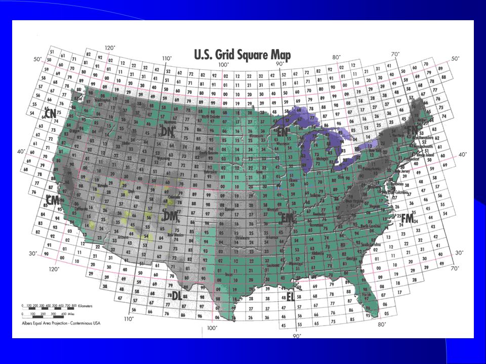
Location Information lRadio direction finding (RDF) is used to locate RF transmissions and or noise. lThe fox hunting slide that follows has more RDF information. lAPRS is Automatic Position Reporting System –Supports quick real-time exchange of information. lPosition, can include moving position via GPS lStatus and messages including inquiries. –Each station with new information transmits his new data to everyone in the net and every station captures that information for consistency to all participants. lInternet linking can be included. lLatitude and longitude define exact position. lGrid squares define close position. –A picture is worth 1000 of words.

100
HAM Satellites lHAM satellites are repeaters, they use different input (uplink) and output (downlink) frequencies. –World wide communication is possible when both stations have a clear path to the satellite. –By using the minimum needed transmitter power you prevent the satellite’s radio receiver from overloading. lTo use a satellite your license class must allow operation on its uplink frequency. lSatellites move, antenna pointing may be required. –LEOs Low Earth Orbit satellites move fast, pointing is required. –The longest path to a satellite that is on the horizon. lIt is also the one that changes least with time. lEasiest for antenna pointing. lSatellite rotation may cause spin fading.

101
More on HAM Satellites lDue to motion their frequencies have Doppler shift. –Keplerian elements define the orbit. –Satellite tracking software allow 3dimensional (azimuth & elevation) antenna pointing and Doppler shift correction. lSatellite beacons contain information about them. lThe International Space Station’s HAM operations are on VHF (2 meters) & UHF (70 cm.) frequencies. –Any Technician licensed HAM can contact it. –International space station contact good for about 4 to 6 min. lThe building and launch of most amateur radio satellites is coordinated by AMSAT. –the Radio Amateur Satellite Corporation. lThe HAM bandplan has satellite sub-bands. –435 to 438 MHz is the 70 centimeter satellite sub-band.
 antenna pointing and Doppler shift correction. lSatellite beacons contain information about them. lThe International Space Station’s HAM operations are on VHF (2 meters) & UHF (70 cm.) frequencies. –Any Technician licensed HAM can contact it. –International space station contact good for about 4 to 6 min. lThe building and launch of most amateur radio satellites is coordinated by AMSAT. –the Radio Amateur Satellite Corporation. lThe HAM bandplan has satellite sub-bands. –435 to 438 MHz is the 70 centimeter satellite sub-band..")
102
Fox Hunting & Contesting lFox hunting; using RDF to locate a TX lA direction vector to the signal is recorded. lRepeat from other location/s lMultiple vectors intersect at the source. –Highest amplitude; gain antenna rotated to direction. –Amplitude comparison; Equal signal amplitude from 2 antennas with over lapping patterns rotated together. –Phase comparison; 2 antennas equidistant to source have the same phase, source broadside to them. lContesting –Work as many other HAM stations as possible during the contest time period following contest rules. l Winning operators have developed great operating skills (minimizing the time to convey the requited information), have picked the right tine for each band, have optimizes their station and may even have had a little luck.
, have picked the right tine for each band, have optimizes their station and may even have had a little luck..")
103
RACES & ARES lRadio Amateur Civil Emergency Service. –Supports local state and federal governments. –You must register with the local civil defense origination to participate. lAmateur Radio Emergency Service. –Supports agencies I.e. red cross, weather service etc. –Any HAM can participate. lBoth provide communications during emergencies. lEmergency nets. –Net control should be a station that has a strong clear signal. –After check in, TX only when asked or if an emergency. –In an emergency and no net, do not wait, start it yourself. lTake check-ins pass off control when required. lAvoid casual chatter when ever you are involved in a public service net, it may interfere with important info.

104
VHF / UHF Operating lThe higher the frequency easier to propagate through small openings. –VHF is better at penetrate buildings, than VHF. –But the higher the frequency the greater the path loss. lRepeaters are vertically polarized. –HT held with its antenna vertical has lowest path loss. lIf your direct line of sight to a repeater is blocked moving / rotating the antenna may open a reflective path and / or provide multipath enforcement. lIf operation while moving multipath can cause the signals to have AM, picket fence modulation. –Named picket fence as it can sound like a stick chicking the fence as someone walks along it, faster travel faster clicks. lAurora reflection is also a moving multipath generator. –Signals very and sound different (garbled).
..")
105
Electrical Safety l1/10 amp (100 ma) of current may be fatal to the heart. –Disrupts body electrical functions –Involuntary Contractions and Heating lVoltages over 30 volts can be dangerous. –Use safety interlock switches with higher voltages. –High voltage capacitors can hold lethal charges. lAll should know location & use of main power switch. lGround all your equipment for safety and minimum EMI. –The 110V green wire is used only for chassis ground. lGround fault interrupters add additional safety. lFuse or circuit breaker required for all equipment. –Interrupts power if overload, prevent fire but only if correct size. –Fuse both lines for mobile radios at battery/source.

106
Lightning Safety lGround all radio and connected equipment. –Minimum 8 foot ground rod at each tower leg bounded to legs and each other with short wide connections. –Follow local building codes. lUse lightning protectors on all antenna & rotor lines. lControlling lightning current flow prevents electric shock & fires. –Large currents result in large voltages with R>0 –10,000 Amps / 0.01 ohms = 100 volts –To avoid large voltage differences between equipments bonding must be very low resistance & Inductance. –Wide conductors have low inductance. lExtra precautions during a storm. –Disconnect antennas & separate from equipment. –Unplug power cables from equipment. –Stay out of radio room.

107
Antenna Safety lDo not put towers and antennas or feed lines near or where they can contact High Voltage lines. –10 foot minimum safety margin if one falls. lThere are tower height restrictions near airports. lKeep antennas away from places where they can be contacted during transmission. –Even low power can cause an RF burn. lThe metal roof of automobile is the safest antenna mobile mounting spot as it is hardest to reach and the roof provides good shielding to the occupants. lDo not work on a tower / antenna if storm possible lMake sure tower & guys are in good condition.

108
More Antenna Safety lNever climb a crank-up tower unless it is full down. –It is a guillotine if a cable breaks. lDo not work alone & wear safety harness. –Tower and guy wires in good condition before climbing. lFollow manufacture’s instructions. lStainless steal hardware minimizes corrosion lWhen working under the person on the tower wear a safety hat and safety glasses. lBring all tools needed to minimize trips up tower. lUse a gin pole when lifting so not to lift above tower. –Temporary pole above tower with pulley and cable on top. lWhen using a Bow and Arrow or a Sling Shot practice People, Property, Power line (PPP) safety.
 safety..")
109
Radiation Identification

110
RF Safety lAmateur Radio Transmitters do not emit any ionizing radiation. lAmateur Radio Transmitters do emit RF heating radiation, like microwave ovens. –Heating is dependent upon the material, the RF frequency and the RF power level. lThe FCC requires all radio transmitters to meet RF radiation exposure limits to assure a safe operating environment for amateurs, their family and neighbors. lThe FCC radiation Maximum Permissible Exposure (MPE) limits are defined in the FCC rules part 1 and in the FCC office of Engineering and Technology (OTE) bulletin 65.
 limits are defined in the FCC rules part 1 and in the FCC office of Engineering and Technology (OTE) bulletin 65..")
111
RF Safety Understanding. lAll amateurs are responsible for not exceeding the MPE limits. lYou also must indicate that you have read and understand these rules on the amateur license application form at the time of application. lThe limits are in milliwatts per square centimeter as a function of frequency. lThe following FCC graph will aid in understanding the limits. lWe will also provide an easy way to be safe and to comply with the FCC requirements.

112
RF Safety Exposure Limits

113
More RF Safety More RF Safety lThe MPE is not uniform across the RF spectrum because the body absorbs some frequencies better than others. –30 to 300 MHz are the frequencies that are easiest for the body to absorb and convert to heat. –MPE levels are also different for controlled (your property) and uncontrolled environments (where anybody can be). lEyes are the most sensitive, as heating can cause cataracts. –HTs (used within 20 cm from body) all have limits on RF power to meet RF safety. –For extra safety keep the antenna of a hand-held away from your eyes. –Never look into an open wave guide when RF is applied. –Never operate a power amplifier with its shields / covers removed.
 and uncontrolled environments (where anybody can be). lEyes are the most sensitive, as heating can cause cataracts. –HTs (used within 20 cm from body) all have limits on RF power to meet RF safety. –For extra safety keep the antenna of a hand-held away from your eyes. –Never look into an open wave guide when RF is applied. –Never operate a power amplifier with its shields / covers removed..")
114
RF Safety Compliance lIf you your antenna (including repeater antennas) is collocated with other antennas the total radiation from all transmitters must be considered. lYou do not have to make measurements or perform complex calculations or use computer models to verify that you meet the requirements. –But you can use them as a way to comply. lSimple tables are available in the FCC office of Engineering and Technology (OTE) bulletin 65, and from other sources including the ARRL. lThe FCC has provided an even easier way to verify that you meet the requirement, as no evaluation is required if you have PEP into the antenna below 50 watts.
 bulletin 65, and from other sources including the ARRL. lThe FCC has provided an even easier way to verify that you meet the requirement, as no evaluation is required if you have PEP into the antenna below 50 watts..")
115
MPE Evaluation Limits

116
Easy MPE Evaluation lOperating at 50 watts or less would in itself be sufficient to meet the safe operating environment rules. lFurthermore duty factor reductions are allowed as heating is duty factor dependent.

117
Easy Compliance lSSB operation at 100 W. or less would also qualify as a duty factor of 50 % is given, even with heavy speech compression. lConversational CW at less than 125 watts (0.4 duty factor * 125 W. = 50 W.) would also qualify. lIn addition if you only use the transmitter for 3 minutes out of 6 minutes you can double the above qualifying power levels for a controlled environment (15 out of 30 minuets for an uncontrolled environ.) lLast but not least, note that the power levels given are at the antenna, hence cable losses apply.
 would also qualify. lIn addition if you only use the transmitter for 3 minutes out of 6 minutes you can double the above qualifying power levels for a controlled environment (15 out of 30 minuets for an uncontrolled environ.) lLast but not least, note that the power levels given are at the antenna, hence cable losses apply..")
118
More Easy Compliance lMost will meet the requirements by making note of the power run on each band. lThe note of your evaluation is kept available at the station, it is not mailed to the FCC or anybody. lIF you are running more power or have antennas with gain, then use the tables in FCC Office of Engineering and Technology (OTE) bulletin 65. –http://www.fcc.gov/oet/info/documents/bulletins/ lIn most cases these tables will eliminate the need for calculations or measurements. –The tables take into account power, antenna gain (pattern) distance and frequency. A sample table follows. lReevaluate if you change equipment.
 bulletin 65. – lIn most cases these tables will eliminate the need for calculations or measurements. –The tables take into account power, antenna gain (pattern) distance and frequency. A sample table follows. lReevaluate if you change equipment..")
119
Table Exerts

120
Good Luck I hope to talk to you on a HAM band. W9PE WWW.W9PE.US

Similar presentations


![SUBELEMENT T4 [2 Exam Questions - 2 Groups] Amateur radio practices and station setup.](/12/3394291/big_thumb.jpg "SUBELEMENT T4 [2 Exam Questions - 2 Groups] Amateur radio practices and station setup.>")


 -Repeater What bands can it work? MF- 160, 80, 75 40 meters (often referred.>")


>")
