Download presentation
Presentation is loading. Please wait.

1
CHAPTER 1: Soil Exploration

2
Contents : 1.1 Introduction 1.2 Boring of Holes 1.2.1 Auger Method 1.2.1.1 Hand Operated Augers 1.2.1.2 Power Driven Augers 1.2.1.3 Wash Boring 1.2.1.4 Rotary Drilling 1.2.1.5 Coring Bits 1.3 Sampling of soils 1.4 Disturbed Samples 1.4.1 Open Drive Sampler

3
Contents : 1.5 Standard Penetration Test (SPT) 1.5.1 Drill Rod, Sampler and Borehole Corrections 1.5.2 Correction Factor for Overburden Pressure in Granular Soils 1.5.3Hammer Efficiency Correction 1.6 Cone Penetration Test (CPT) 1.7 Operation of Penetrometer 1.8 Correlation between SPT and CPT 1.9 Geophysical Exploration 1.9.1 Seismic Refraction Method 1.9.2 Electrical Resistivity Method Wenner Method 1.10 Soil Report 1.11 Borehole Log
 Drill Rod, Sampler and Borehole Corrections Correction Factor for Overburden Pressure in Granular Soils 1.5.3Hammer Efficiency Correction 1.6 Cone Penetration Test (CPT) 1.7 Operation of Penetrometer 1.8 Correlation between SPT and CPT 1.9 Geophysical Exploration Seismic Refraction Method Electrical Resistivity Method Wenner Method 1.10 Soil Report 1.11 Borehole Log")
4
1.1 Introduction : The object of site investigation is to obtain reliable, specific and detailed information about the soil/rock and groundwater conditions at a site for enabling engineers in the safe andeconomic design and execution of engineering works. The investigation should yield precise information about the following: i. Order of occurrence and extent of soil/rock strata. ii. Nature and engineering properties of the soil/rock strata. iii. Location of groundwater table and its fluctuation.

5
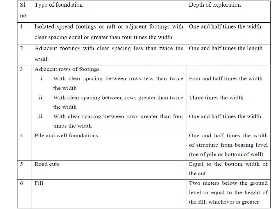
Depth of exploration (IS: 1892-1979) This depth up to which the increase in stress due to structural loading causes shear failure or excessive settlement of foundation is known as significant depth. This depth of investigation is generally taken as the depth of pressure bulb of intensity 0.1qwhere ‘q’ is the intensity of loading at the base of foundation.

7
The number and spacing of borings/test pits : Depends on the type and size of foundations and extent of variation in soil conditions. IS 1892 makes the following recommendations: i. For a compact building site covering an area of about 0.4 hectare, one bore hole or trial pit in each corner and one in the centre should be adequate ii. For smaller and less important buildings even one bore hole or trail pit in the centre will sufficiant. iii. For very large areas covering industrial and residential colonies, the geotechnical nature of the terrain will help in deciding the number of bore holes or trail pits.

8
iv. Cone penetration tests may be performed at every 50 m by dividing the area in a grid pattern and number of bore holes or trail pits decided by examining the variation in penetration curves. The cone penetration tests may not be possible at sites having gravelly or boulderous strata. In such cases geophysical methods may be suitable.

9
1.2 Boring of Holes : Making or drilling bore holes into the ground. The common methods of advancing bore holes are described below.

10
1.2.1 Auger Method : Soil auger is a device that is useful for advancing a bore hole into the ground. Augers may be hand-operated or power-driven; The soil auger is advanced by rotating it while pressing it into the soil at the same time. It is used primarily in soils in which the bore hole canbe kept dry and unsupported As soon as the auger gets filled with soil, it is taken out and the soil sample collected. 1.2.1.1 Hand Operated Augers : The depths of the holes are normally limited to a maximum of 10 m by this method.

11
1.2.1.1 Hand Operated Augers : These augers are generally suitable for all types of soil above the water table but suitable only in clayey soil below the water table. A string of drill rods is used for advancing the boring. The diameters of the holes normally vary from 10 to 20 cm. Hand operated augers are not suitable in very stiff to hard clay nor in granular soils below the water table.

12
1.2.1.2 Power Driven Augers : Holes may be drilled by this method rapidly to depths of 60 m or more. This method may be used in all types of soil including sandy soils below the water table It is not suitable if the soil is mixed with gravel, cobbles etc. The central stem of the auger flight may be hollow or solid. A hollow stem is sometimes preferred since standard penetration tests or sampling may be done through the stem without lifting the auger from its position in the hole. Besides, the flight of augers serves the purpose of casing the hole.

13
The hollow stem can be plugged while advancing the bore and the plug can be removed while taking samples or conducting standard penetration tests as shown in Fig 1.2.

14
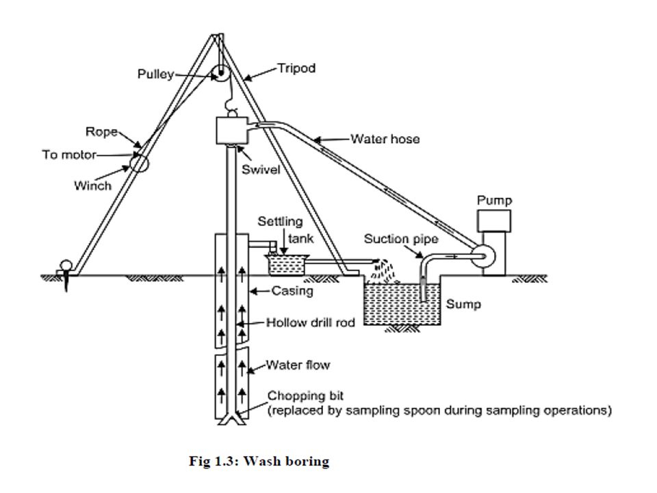
1.2.1.3Wash Boring : Soil exploration below the ground water table is usually very difficult to perform by means of pits or auger-holes. Wash boring in such cases is a very convenient method provided the soil is sand, silt, or clay. The method is not suitable if the soil is mixed with gravel or boulders. (Fig 1.3 shows the assembly for a wash boring.) To start with, the hole is advanced a short depth by auger. And then a casing pipe is pushed to prevent the sides from caving in. The hole is then continued by the use of a chopping bit fixed at the end of a string of hollow drill rods. A stream of water under pressure is forced through the rod and the bit into the hole which loosens the soil and as the water flows up around the pipe, the loosened soil in suspension in water is discharged into a tub.
 To start with, the hole is advanced a short depth by auger. And then a casing pipe is pushed to prevent the sides from caving in. The hole is then continued by the use of a chopping bit fixed at the end of a string of hollow drill rods. A stream of water under pressure is forced through the rod and the bit into the hole which loosens the soil and as the water flows up around the pipe, the loosened soil in suspension in water is discharged into a tub..")
15
1.2.1.3Wash Boring : The soil in suspension settles down in the tub and the clean water flows into a sump which is reused for circulation. The bit which is hollow is screwed to a string of hollow drill rods supported on a tripod by a rope or steel cable passing over a pulley and operated by a winch fixed on one of the legs of the tripod. The purpose of wash boring is to drill holes only and not to make use of the disturbed washed materials for analysis. Whenever an undisturbed sample is required at a particular depth, the boring is stopped, and the chopping bit is replaced by a sampler. The sampler is pushed into the soil at the bottom of the hole and the sample is withdrawn.

17
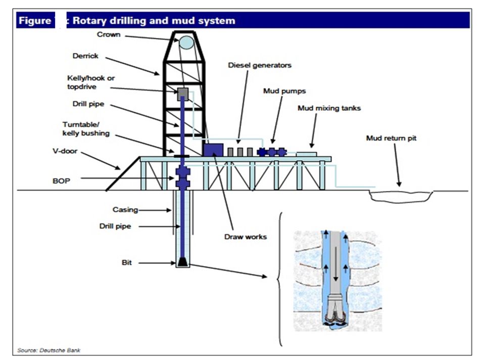
1.2.1.4 Rotary Drilling : In the rotary drilling method a cutter bit or a core barrel with a coring bit attached to the end of a string of drill rods is rotated by a power rig. The rotation of the cutting bit shears or chips the material penetrated and the material is washed out of the hole by a stream of water just as in the case of wash boring. Rotary drilling is used primarily for penetrating the overburden between the levels at which samples are required. Coring bits, on the other hand, cut an annular hole around an intact core which enters the barrel and is retrieved. Thus the core barrel is used primarily in rocky strata to get rock samples.

18
As the rods with the attached bit or barrel are rotated, a downward pressure is applied to the drill string to obtain penetration, and drilling fluid under pressure is introduced into the bottom of the hole through the hollow drill rods and the passages in the bit or barrel. This drilling fluid serves the dual function of cooling the bit as it enters the hole and removing the cuttings from the bottom of the hole as it returns to the surface through the annular space between the drill rods and the walls of the hole. In an uncased hole, the drilling fluid also serves to support the walls of the hole. When boring in soil, the drill bit is removed and replaced by a sampler when sampling is required, but in rocky strata the coring bit is used to obtain continuous rock samples.

20
1.2.1.5 Coring Bits : The three basic categories of coring bits in use are diamond, carbide insert, and saw tooth. Diamond coring bits may be of the surface set or diamond impregnated type. The most versatile of all coring bits are the diamond coring bits. This is because they produce high quality cores in rock materials ranging from soft to extremely hard. Carbide insert bits use tungsten carbide in lieu of diamonds. Bits of such type are used to core soft to medium hard rock. Even though they are less expensive than diamond bits, the rate of drilling is slower than with diamond bits..

21
Figure Coring Bits

22
1.3Sampling of soils : Soils met in nature are heterogeneous in character with a mixture of sand, silt and clay in different proportions. In water deposits, there are distinct layers of sand, silt and clay of varying thicknesses and alternating with depth. A satisfactory design of a foundation depends upon the accuracy with which the various soil parameters required for the design are obtained. The accuracy of the soil parameters depends upon the accuracy with which representative soil samples are obtained from the field.

23
1.4Disturbed Samples Auger samples may be used to identify soil strata and for field classifications tests, but are not useful for laboratory tests. The cuttings or chopping from wash borings are of little value except for indicating changes in stratification to the boring supervisor. The material brought up with the drilling mud is contaminated and usually unsuitable even for identification. For proper identification and classification of a soil, representative samples are required at frequent intervals along the bore hole. Representative samples can usually be obtained by driving or pushing into the strata in a bore hole an open-ended sampling spoon called a split spoon sampler.

24
Split Spoon Sampler : It is made up of a driving shoe and a barrel. The barrel is split longitudinally into two halves with a coupling at the upper end for connection to the drill rods. The dimensions of the split spoon are given in Fig. In a test the sampler is driven into the soil a measured distance. After a sample is taken, the cutting shoe and the coupling are unscrewed and the two halves of the barrel separated to expose the material. Experience indicates that samples recovered by this device are likely to be highly disturbed and as such can only be used as disturbed samples.

25
The samples so obtained are stored in glass or plastic jars or bags, referenced and sent to the laboratory for testing. If spoon samples are to be transported to the laboratory without examination in the field, the barrel is often cored out to hold a cylindrical thin-walled tube known as a liner. After a sample has been obtained, the liner and the sample it contains are removed from the spoon and the ends are sealed with caps or with metal discs and wax. Samples of cohesion less soils below the water table cannot be retained inconventional sampling spoons without the addition of a spring core catcher. Split Spoon Sampler :

26
Fig: Split spoon sampler Two types of samplers are described here. They are 1. Open drive sampler 2. Piston sampler.

27
1.4.1Open Drive Sampler The wall thickness of the open drive sampler used for sampling may be thin or thick according to the soil conditions met in the field. The samplers are made of seamless steel pipes. A thin-walled tube sampler also called as Shelby tube sampler (Fig. 1.5), consists of a thin wall metal tube connected to a sampler head. The sampler head contains a ball check valve and ports which allows the escape of air or water from the sample tube as the sample enters it. The thin wall tube, which is normally formed from 1/16 to 1/8 inch metal.
, consists of a thin wall metal tube connected to a sampler head. The sampler head contains a ball check valve and ports which allows the escape of air or water from the sample tube as the sample enters it. The thin wall tube, which is normally formed from 1/16 to 1/8 inch metal..")
28
Fig. : Shelby tube sampler

29
The wall thickness is governed by the area ratio, Ar, which is defined as, where, do= outside diameter di = inside diameter Ar is a measure of the volume of the soil displacement to the volume of the collected sample. well designed sampling tubes has an area ratio of about 10 percent. However, the area ratio may have to be much more than 10percent when samples are to be taken in very stiff to hard clay soils mixed with stones to prevent the edges of the sampling tubes from distortion during sampling.

30
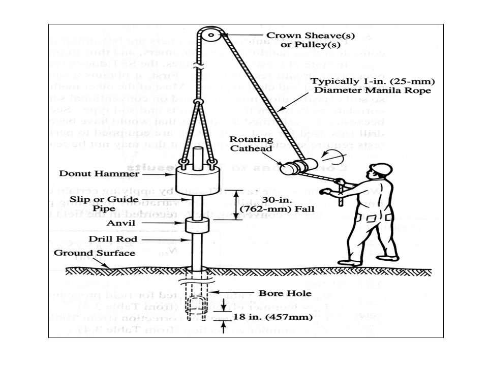
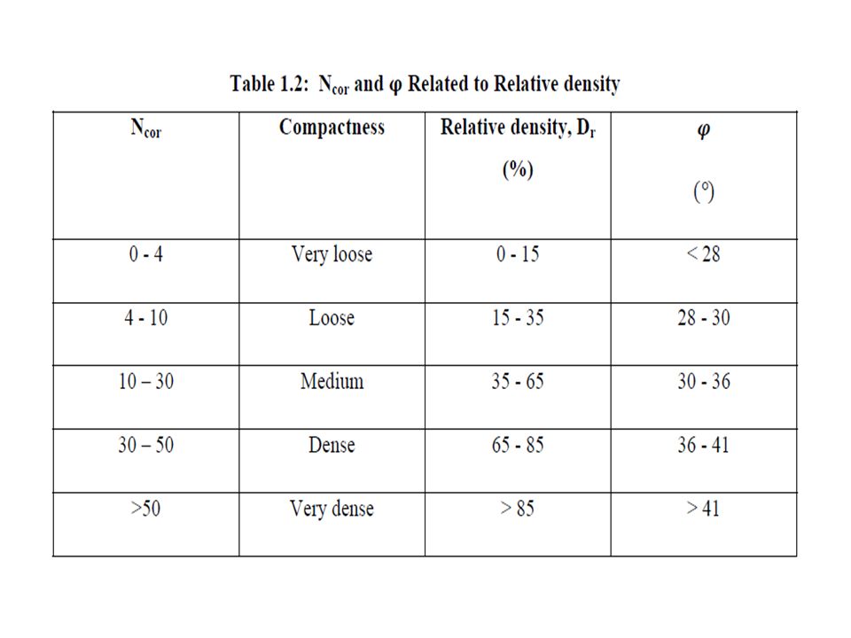
1.5Standard Penetration Test (SPT) The SPT is the most commonly used in situ test in a bore hole. The test is made by making use of a split spoon sampler shown in Fig1.4. The method has been standardized as ASTM D-1586 in USA and IS 2131 in India. The method of carrying out this test is as follows: 1.The split spoon sampler is connected to a string of drill rods and is lowered into the bottom of the bore hole which has been drilled and cleaned in advance. 2. The sampler is driven into the soil strata to a maximum depth of 450 mm by making use of a 65 kg weight falling freely from height of 75 cm on to an anvil fixed on the top of drill rod.

31
3. The weight is guided to fall along a guide rod. The weight is raised and allowed to fall by means of a manila rope, one end tied to the weight and the other end passing over a pulley on to a hand operated winch or a motor driven cathead. 3. The number of blows required to penetrate each of the successive 150 mm depths is counted to produce a total penetration of 450 mm. 4. To avoid seating errors, the blows required for the first 150 mm of penetration are not taken into account; blows required to only increase the penetration from 150 mm to 450 mm constitute the N- value. As per some codes of practice if the N-value exceeds 100, it is termed as refusal, and the test is stopped even if the total penetration falls short of the last 300 mm depth ofpenetration.

32
Standardization of refusal at 100 blows allows all the drilling organizations to standardize costs so that higher blows if required may be eliminated to prevent the excessive wear and tear of the equipment. The SPT is conducted normally at 1.5 m interval or at the change of stratum. The intervals may be increased at greater depths if necessary.

35
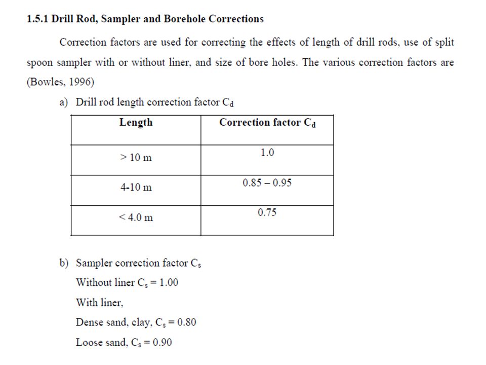
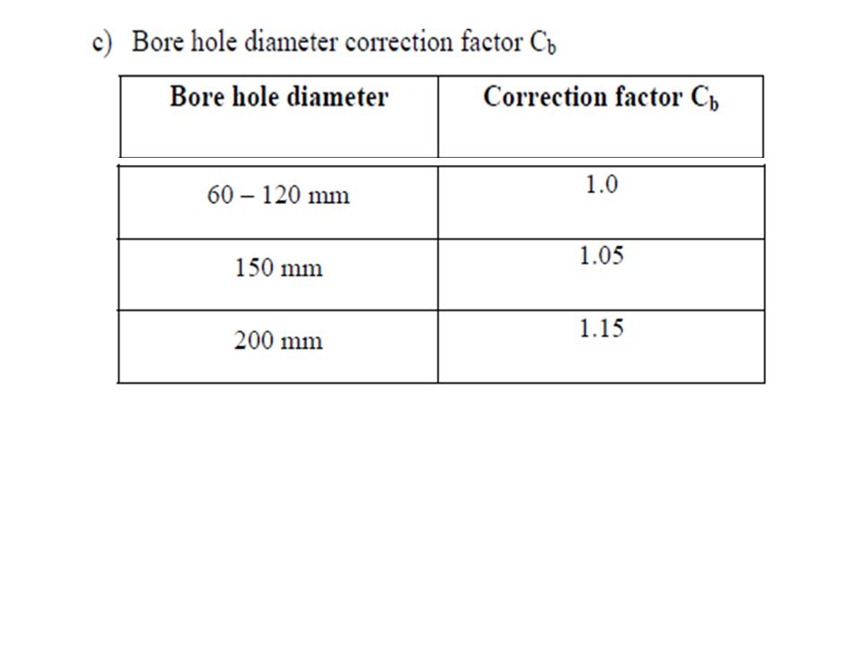
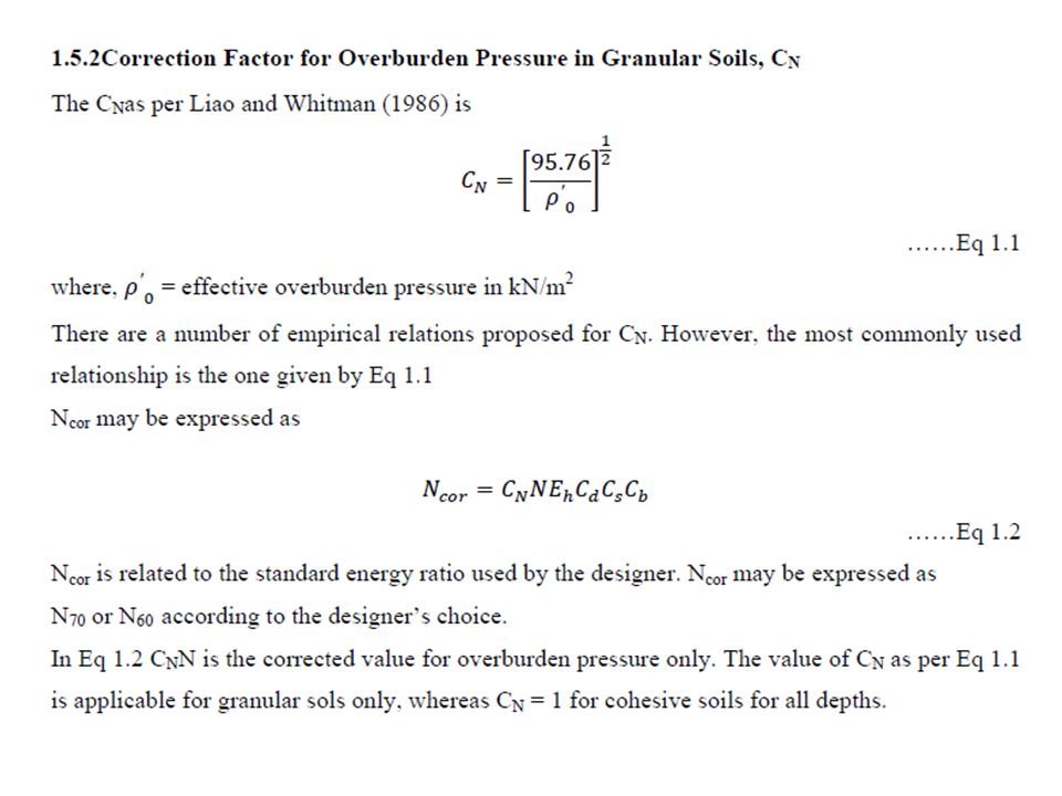
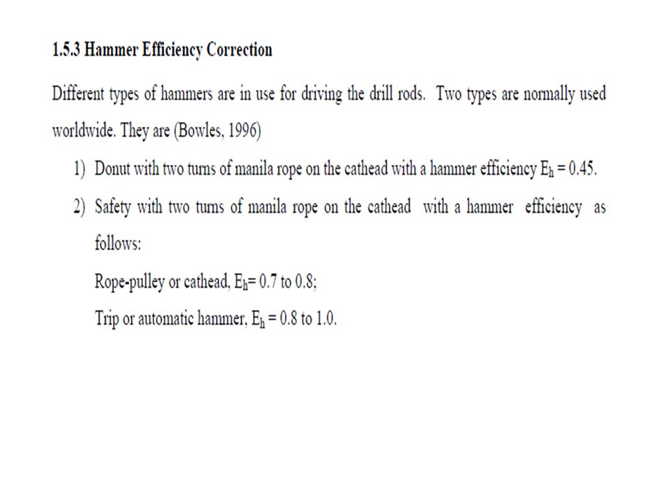
Three types of corrections are normally applied to the observed N values. They are: 1) Drill rod, sampler and borehole corrections 2) Correction due to overburden pressure 3) Hammer Efficiency Correction
 Drill rod, sampler and borehole corrections 2) Correction due to overburden pressure 3) Hammer Efficiency Correction.")
42
1.6Cone Penetration Test (CPT) The static cone penetration test normally called the Dutch cone penetration test. One of the greatest values of the CPT consists of its function as a scale model pile test. Empirical correlations established over many years permit the calculation of pile bearing capacity directly from the CPT results without the use of conventional soil parameters. The popularity of the CPT can be attributed to the following three important factors: 1) General introduction of the electric penetrometer providing more precise measurements, and improvements in the equipment allowing deeper penetration.
 General introduction of the electric penetrometer providing more precise measurements, and improvements in the equipment allowing deeper penetration..")
43
2) The need for the penetrometer testing in-situ technique in offshore foundation investigations in view of the difficulties in achieving the adequate sample quality in marine environment. 3) The addition of other simultaneous measurements to the standard cone penetrometersuch as soil temperature and pore pressure.
 The addition of other simultaneous measurements to the standard cone penetrometersuch as soil temperature and pore pressure..")
44
The sequence of operation of the penetrometer shown in Fig. Position 1: The cone and friction jacket assembly in a collapsed position. Position 2: The cone is pushed down by the inner sounding rods to a depth until a collar engages the cone. The pressure gauge records the total force Qc to the cone. Normally a = 40 mm. Position 3: The sounding rod is pushed further to a depth b. This pushes the friction jacket and the cone assembly together; the force is Qt. Normally b = 40 mm. 1.7Operation of Penetrometer

45
Position 4:The outside mantle tube is pushed down a distance a + b which brings the cone assembly and the friction jacket to position 1. The total movement = a + b = 80 mm. The process of operation illustrated above is continued until the proposed depth is reached. The cone is pushed at a standard rate of 20 mm per second. The mechanical penetrometer has its advantage as it is simple to operate and the cost of maintenance is low. The quality of the work depends on the skill of the operator. The depth of CPT is measured by recording the length of the sounding rods that have been pushed into the ground.

46
Fig 1.7: Operation of cone Penetrometer

48
1.8Correlation between SPT and CPT

49
1.9 Geophysical Exploration : Measure changes in certain physical characteristics of these materials, for example magnetism, density, electrical resistivity, elasticity or a combination of these properties. However, the utility of these methods in the field of foundation engineering is very limited since the methods do not quantify the characteristics of the various substrata. Vital information on ground water conditions is usually lacking. Geophysical methods at best provide some missing information between widely spaced bore holes but they cannot replace bore holes.

50
Two methods of exploration, 1. Seismic Refraction Method, 2. Electrical Resistivity Method. 1.9.1Seismic Refraction Method

51
The seismic refraction method is based on the fact that seismic waves have different velocities in different types of soils (or rocks). The waves refract when they cross boundaries between different types of soils. These waves are classified as either direct, reflected or refracted waves. The shock waves are picked up by geophones. The depth H1 of the top strata (provided the thickness of the stratum is constant) can be estimated from the formula,
 can be estimated from the formula,.")
52
The thickness of the second layer (H2) is obtained from, 1.9.2Electrical Resistivity Method
 is obtained from, 1.9.2Electrical Resistivity Method")
53
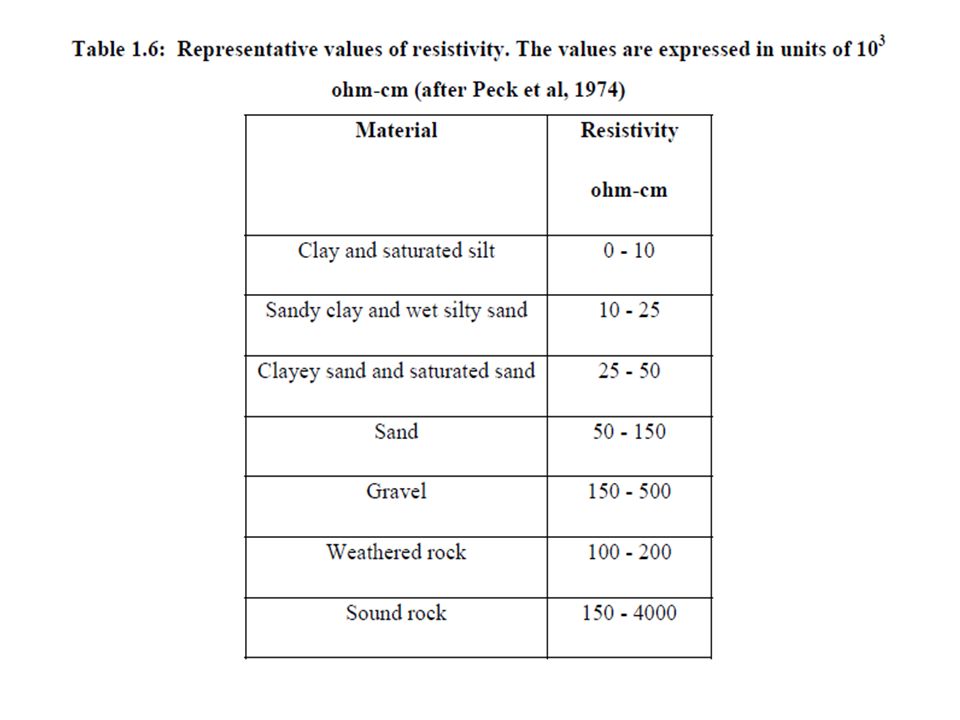
This method depends on differences in the electrical resistance of different soil (and rock) types. The flow of current through a soil is mainly due to electrolytic action and therefore depends on the concentration of dissolved salts in the pores. The minerals are poor conductors of current. The resistivity of soil, therefore, decreases as both water content and concentration of salts increase. Dense clean sand above the water table, for example, would exhibit a high resistivity due to its low degree of saturation and virtual absence of dissolved salts. Saturated clay of high void ratio, on the other hand, would exhibit a low resistivity due to the relative abundance of pore water and the free ions in that water.

55
1.10 Soil Report : A report is the final document of the whole exercise of soil exploration A good report should normally comprise the following: 1. A general description of the nature of the project and its importance. 2. A general description of the topographical features and hydraulic conditions of the site. 3. A brief description of the various field and laboratory tests carried out. 4. Analysis and discussion of the test results 5. Recommendations 6. Calculations for determining safe bearing pressures, pile loads, etc.

56
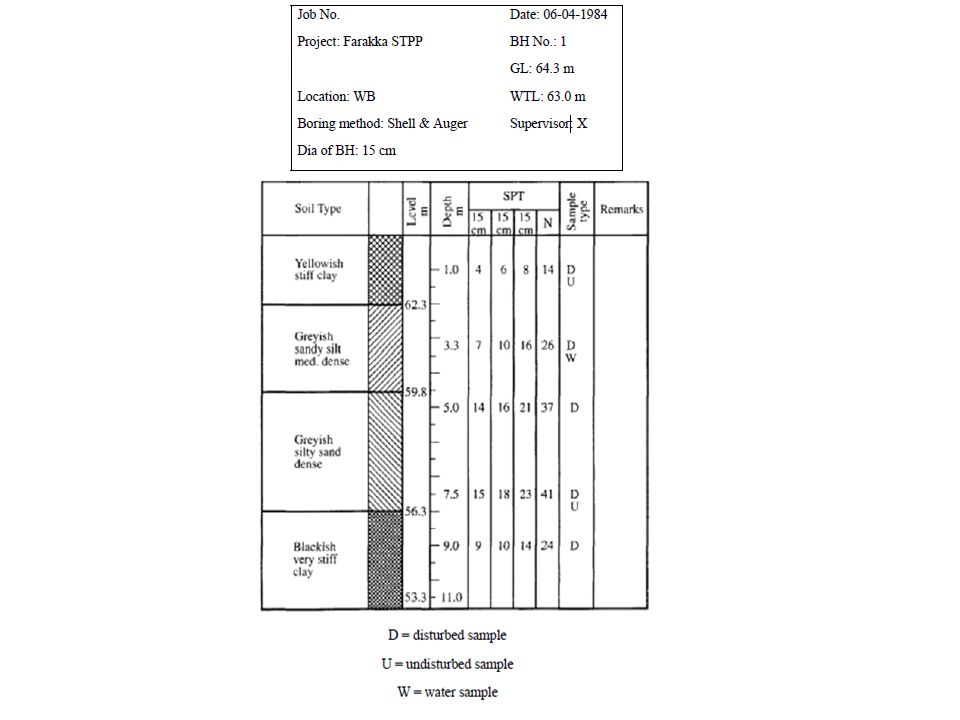
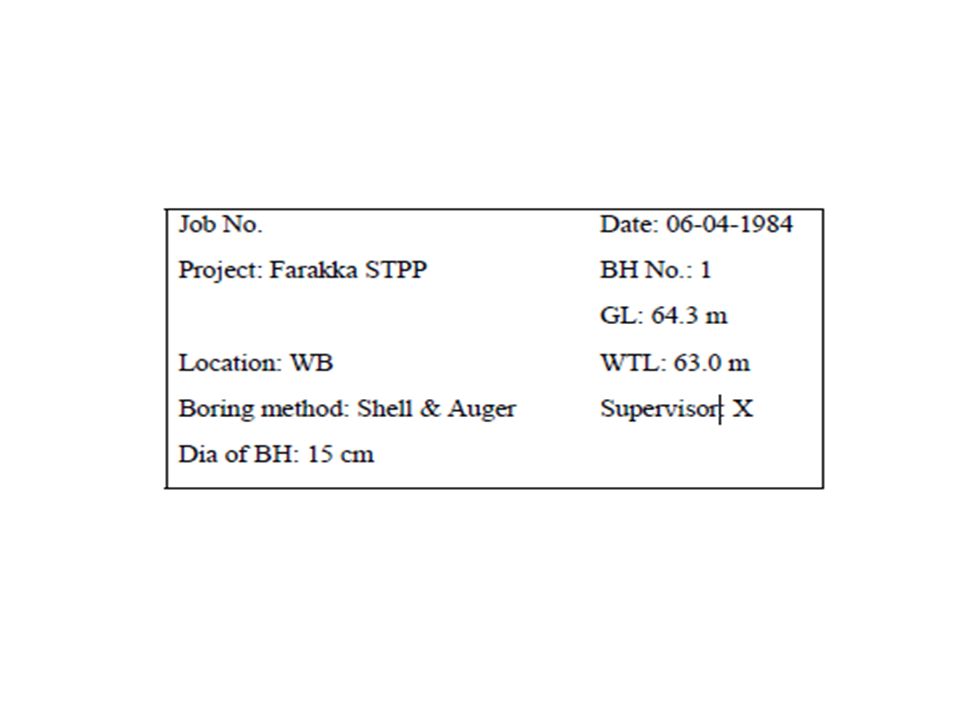
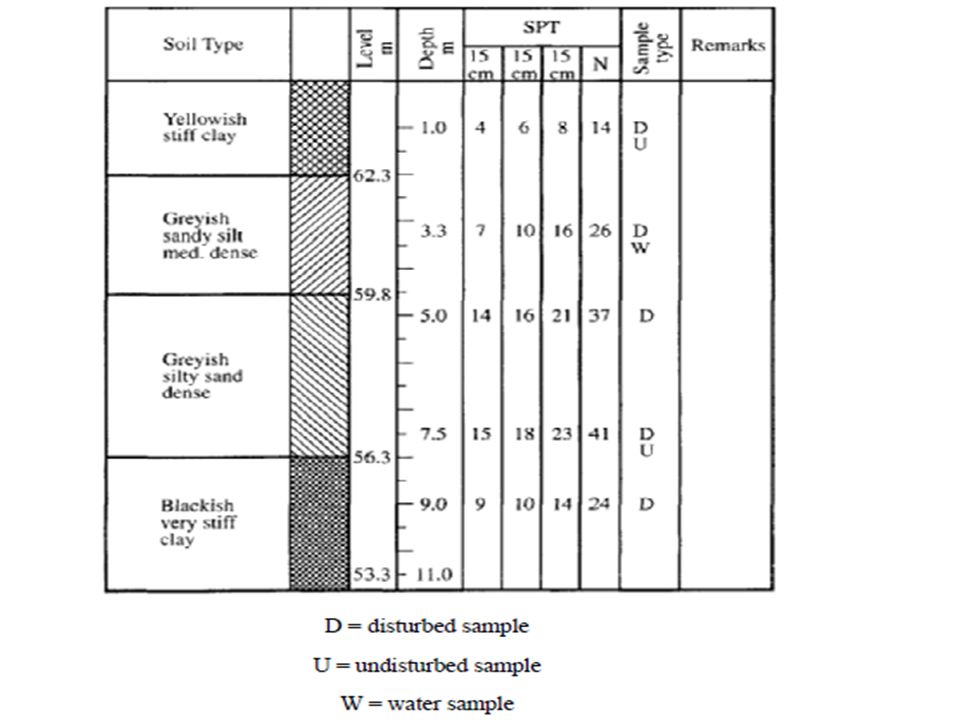
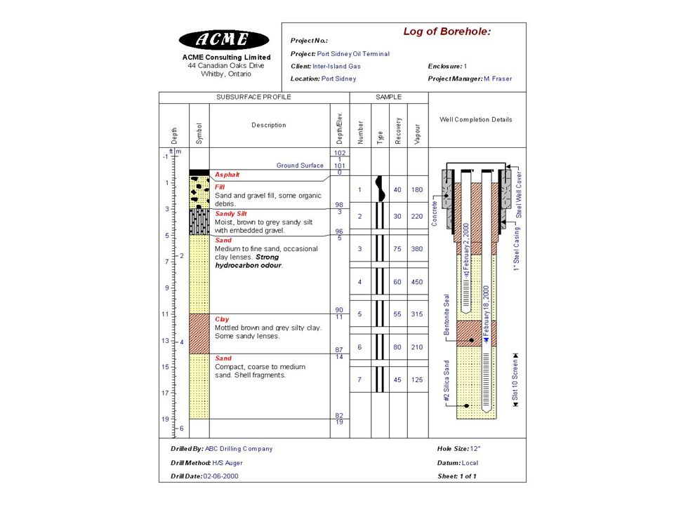
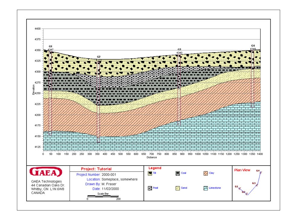
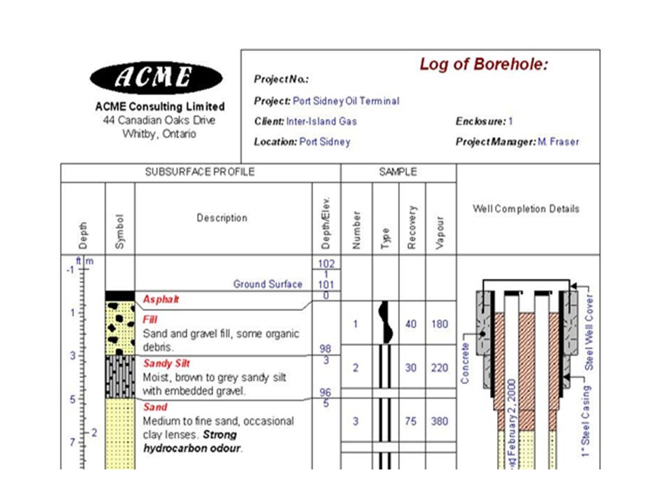
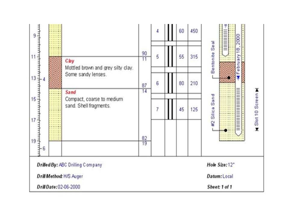
7. Tables containing bore logs, and other field and laboratory test results 8. Drawings which include an index plan, a site-plan, test results plotted in the form of graphs and charts, soil profiles, etc. 1.11BoreholeLog A borehole log is a record of information obtained from in situ tests and summary of laboratory tests on samples for a particular borehole. It includes description or classification of various soil / rock types at different depths with summary of essential properties including presence or otherwise of ground water table.

Similar presentations


>")


>")


