Download presentation
Presentation is loading. Please wait.

1
GPIOs and Linux Communicating with the outside world Presented by Gene Sally gene.sally@gmail.com

2
Today's Presentation ● What are GPIOs ● Getting to know the hardware ● Tracing the GPIO from the data sheet ● Seeing where the GPIO appears on a board ● Telling the kernel about the the hardware ● Higher-level interfaces to GPIOs ● GPIOlib, gpio_keys, sysfs

3
Example Hardware ● GPIOs are very hardware specific, so this uses an existing board as a frame of reference ● Mini2440 board ● Fun project board, about ~US $100 ● There are many, many other COTS boards with GPIOs ● Beagle board (TI OMAP ) ● Glomation boards ● Gumstix, your custom hardware, whatever ● Not here to advertise for a certain hardware vendor! ● Your GPIO implementation will be different... … but the concepts will be the same!

4
What are GPIOs ● General Purpose Input/Output ● One of processor's way of communicating with the outside world ● Usually communicate some binary state ● But there are analog GPIOs as well, these aren't as common as digital GPIOs ● We'll stick to digital GPIOs for this presentation

5
What are GPIOs ● GPIOs are part of the processor's hardware design. ● You get what was designed into the hardware! ● Can't add or change the number of GPIOs ● Processor GPIOs != GPIOs available to you ● The board design must “bring out” the GPIO lines so they can be accessed ● If you're designing a completely custom board, this isn't an issue, but you'll need the GPIO lines on the test board

6
Finding GPIO Lines ● Look at the Data sheet ● First for the processor ● Next for the board ● These can't be found by inspection ● There's not standardized GPIO connector on the board ● There's no label that says “GPIOs Right Here” ● Sometimes, they're not exposed by the board's hardware design

7
Actual Data Sheet ● For the Samsung s3c2440 processor ● On page 30, 32 it mentions that there are GPIOs ● But not a lot of detail about how they're implemented... ● Chapter 9... Paydirt! This entire chapter is dedicated to describing how the GPIOs (and the rest of the IO) work ● The data sheet for your processor will be different! ● Like the hardware connector, there's not an industry standard place to put this data ● Sometimes, it will have odd names ● Keep telling yourself it's fun
 work ● The data sheet for your processor will be different. ● Like the hardware connector, there s not an industry standard place to put this data ● Sometimes, it will have odd names ● Keep telling yourself it s fun.")
8
I/O Organization ● Grouped into Ports (or Banks) ● Each port contains some number of pins ● Some pins are bi-directional, others are uni-directional: it all depends on how the processor was designed ● Each port is named ● Usually with a letter, but a number is fine too ● This is a convention, any label could be assigned to the ports ● Each GPIO line will have a number ● Relative to the GPIO Port ● Example: GPIO Port A will have lines 1 – 32
 ● Each port contains some number of pins ● Some pins are bi-directional, others are uni-directional: it all depends on how the processor was designed ● Each port is named ● Usually with a letter, but a number is fine too ● This is a convention, any label could be assigned to the ports ● Each GPIO line will have a number ● Relative to the GPIO Port ● Example: GPIO Port A will have lines 1 – 32")
9
I/O Organization Con't ● Each port will have a control mechanism to configure the lines, commonly called a “control register” ● Things that you can control ● Direction ● Pull-up ● Low-power wake ● Rising or falling edge detection ● Interrupt association ● Page 292 of data sheet for details

10
GPIO Organization GPG A GPG B GPG C Control Register frequently several words Value Register This is a bit mask that has the current state of the GPIO line. Look at the data sheet page 290 for an example. This is one bit per GPIO This is a bit mask that has the current state of the GPIO line. Look at the data sheet page 290 for an example. This is one bit per GPIO A few bits here control direction & bias per the data sheet. Know and love your data sheet! LSB GPG C GPG n MSB LSB MSB LSB

11
Rising or Falling Edge ● Default state is 0 (low) Rising edge Falling edge Time (low) 0 arbitrary time passes here (high) 1
 Rising edge Falling edge Time (low) 0 arbitrary time passes here (high) 1")
12
Rising vs. Falling ● You need to think about your application ● How do you want the system to respond to input ● Keyboard are falling edge devices ● Many buttons for user input are rising edge ● But on the falling edge, you need stop auto repeats, so maybe it's both... ● But rising edge is also frequently used ● For instance, to detect the close of an open switch (like for a door sensor) rising would be used
 rising would be used.")
13
Pull Up or Pull Down Resistors ● You'll here this a lot from the hardware guys (full disclosure: I'm not a hardware guy!) ● This bit of circuitry ensures that circuit is in a default state ● Down == low or off state ● Up == up on on state ● These can be on-board or on chip ● Most of the time, the default state isn't important ● You just need to know what it happens to be so you can plan ● GPIO Lines driven high ● Consume power (most of the time) & reduce battery life. If you care about this, configure GPIOs so that they are powered low by default ● Your hardware engineer will know the right thing to do & questions to ask

14
Let's take a look GPD Configuration Register 00 00 00 00 00 00 00 00 Two bits per port High bit is input or output Low bit is for processor configuration Two bits per port High bit is input or output Low bit is for processor configuration 00 01 00 00 00 00 00 00 00 00 00 00 00 00 00 00 Two bits per port High bit is input or output Low bit is for processor configuration Two bits per port High bit is input or output Low bit is for processor configuration I've made GPD1 an input GPIO!

15
Not all GPIOs are Available ● Some have been reserved by the processor ● SPI/UART ● LCD ● Other stuff... it all depends on the chip in question ● The data sheet will tell you what's available ● They will be marked as reserved ● Sometimes you can change the meaning of the line, but that depends entirely on chip Become friends with the data sheet Become friends with the data sheet

16
What the Processor Giveth ● The board taketh away... ● Available GPIOs on processor != GPIOs available to you ● If you're using a COTS board, you get the GPIOs the board designer gave you ● Sometimes, the pull-ups or high/low state will be enforced in the hardware ● For custom boards, you're more in luck ● You can dictate exactly the GPIOs you want ● Planning is essential, because once the hardware is made, changes become very expensive

17
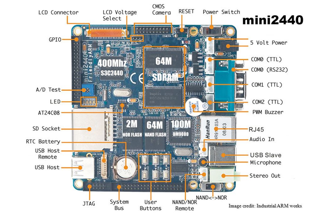
Our board: Mini2440 ● S3c2440 processor (ARM 920t core) ● RAM / Flash / SD RAM ● LCD ● Ethernet ● Serial ● GPIOs Image credit: Industrial ARM works
 ● RAM / Flash / SD RAM ● LCD ● Ethernet ● Serial ● GPIOs Image credit: Industrial ARM works")
19
For example ● In our board... ● Not all GPIO lines have been made available ● Some have been purposed to drive the LCD & serial ports and camera and aren't reachable in an application ● Some GPIO lines are electrically bound with other features – In the mini board, one GPIO is affected by data on the USB line due to the configuration of the board.

20
Look at the Schematic / Data sheet ● Recall how the processor labeled GPIO ports? ● Look for matching labels on the schematic! ● Some of the GPIOs are on a big header ● Some are connected to buttons on the board ● This will tell you what's wired-up for access ● Most of the time the schematic is correct ● Except for when it's wrong ● So... test with a sample board before ordering 1000 for a production run

21
GPIO Port on Mini2440 This header has GPIO lines GPG 0,3,5,6,7,11 Which are lines EINT 8,11,13,14,15,19 to the processor The voltage supply is there too, and so is a ground for making a circuit This header has GPIO lines GPG 0,3,5,6,7,11 Which are lines EINT 8,11,13,14,15,19 to the processor The voltage supply is there too, and so is a ground for making a circuit Image credit: Industrial ARM Works

22
Our Board's Schematic ● The IO Ports on Page 4 are out GPIOs (recall the bank numbering scheme) ● Some of these are already taken for other purposes ● For example the camera interface ● And a serial connector ● For EE's out there, this isn't the best schematic ● You make due with what you have ● Some boards have very poor documentation (even if they're from “big” companies) ● This is exploration as much as it's engineering
 ● Some of these are already taken for other purposes ● For example the camera interface ● And a serial connector ● For EE s out there, this isn t the best schematic ● You make due with what you have ● Some boards have very poor documentation (even if they re from big companies) ● This is exploration as much as it s engineering")
23
One last word about hardware ● Have the EE working on the project create a development or test fixture ● Depending on the volume for the project, the test fixture may be something that is created for manufacturing ● This will have all GPIO lines available as easy to press/switch devices and some LEDs so you can inspect the state ● Very important, because during development, you'll have hardware + software problems ● You may need to attach a scope ● If possible, leave a header on the early production boards for debugging The data sheet for the board and processor is invaluable for debugging.

24
Up one Level: Kernel Services ● Once the board has booted and the resources have been described and initialized, you can step away from the gnarly hardware details ● All of the work so far is in service to making other kernel-level development easier ● For many developers, GPIO development starts here ● You should know how things work up to this point ● There will be hardware and software bugs that require low-level knowledge

25
GPIO Software Stack GPIO Keys Machine / Platform Configuration Linux GPIO Library / Machine GPIO Library Your driver Application Hardware Configuration /sysfs file system

26
GPIO Software Stack ● GPIO Hardware Configuration ● Telling the kernel about the hardware resources ● Early in hardware initialization ● Drivers for GPIO Keys ● Emits “events” when GPIOs are triggered ● Why write a driver? Use GPIO Keys functionality ● /sys access for GPIOs ● A very easy way to access these resources

27
Hardware Configuration for GPIOs ● Create processor macros for each of the GPIOs banks control and data registers, so you can refer to the control and value registers symbolically ● Not necessary, but makes your life much easier ● Probably already defined for your processor / board ● Helper routines for changing and inspecting GPIO configuration ● Help routines for fetching values from value registers ● This is the lowest of the low-level code associated with getting the GPIOs to work correctly.

28
In our example board... arch/arm/mach-s3c2410/include/mach/regs-gpio.h #define S3C2410_GPA0_ADDR0 (1<<0) #define S3C2410_GPA1_ADDR16 (1<<1) #define S3C2410_GPA2_ADDR17 (1<<2) #define S3C2410_GPA3_ADDR18 (1<<3) Each of lines maps back to the GPIO control register information in the processor's data sheet.
 #define S3C2410_GPA1_ADDR16 (1<<1) #define S3C2410_GPA2_ADDR17 (1<<2) #define S3C2410_GPA3_ADDR18 (1<<3) Each of lines maps back to the GPIO control register information in the processor s data sheet..")
29
Machine / Platform Configuration ● Enter: gpiolib (drivers/gpio) ● This is how most engineers work with GPIOs in Linux ● Registration of GPIO data ● GPIO Ports / Banks (called “chips”) ● Range of GPIOs present ● After registration, you can use the existing GPIO infrastructure, which is much higher level
 ● This is how most engineers work with GPIOs in Linux ● Registration of GPIO data ● GPIO Ports / Banks (called chips ) ● Range of GPIOs present ● After registration, you can use the existing GPIO infrastructure, which is much higher level")
30
Registration ● Via gpiochip_add(struct gpio_chip *chip) ● For our board (the mini2440) this is a bit more complicated, as it has custom wrappers around GPIO lib, but the idea is the same... ● Let's take a look: ● arch/arm/plat-s3c64xx/gpiolib.c In most cases, the basic GPIO initialization has been completed by the chip / board vendor as part of the Linux distribution In most cases, the basic GPIO initialization has been completed by the chip / board vendor as part of the Linux distribution

31
Helper routines arch/arm/mach-s3c2410/include/mach/regs-fns.h (impl in arch/arm/plat-s3c24xx/gpio.c) ● This file has routines for configuring and setting the values of the pins. ● In this case, these routines are shared across several different boards ● For your board, they will be somewhere different!

32
GPIO Lib Functions (core) ● Housekeeping functions (see /drivers/gpio/gpiolib.c) ● In our example board, these have hardware specific implementations: static inline int gpio_direction_input(unsigned gpio) static inline int gpio_direction_output(unsigned gpio, int value) static inline int gpio_get_value(unsigned gpio) static inline void gpio_set_value(unsigned gpio, int value)
 ● Housekeeping functions (see /drivers/gpio/gpiolib.c) ● In our example board, these have hardware specific implementations: static inline int gpio_direction_input(unsigned gpio) static inline int gpio_direction_output(unsigned gpio, int value) static inline int gpio_get_value(unsigned gpio) static inline void gpio_set_value(unsigned gpio, int value)")
33
GPIO Data Structures for mini2440 struct s3c_gpio_chip s3c24xx_gpios[] = { [0] = {.base= S3C2410_GPACON,.pm= __gpio_pm(&s3c_gpio_pm_1bit),.chip= {.base= S3C2410_GPA(0),.owner= THIS_MODULE,.label= "GPIOA",.ngpio= 24,.direction_input= s3c24xx_gpiolib_banka_input,.direction_output= s3c24xx_gpiolib_banka_output, }, [1] = {.base= S3C2410_GPBCON,.pm= __gpio_pm(&s3c_gpio_pm_2bit),.chip= {.base= S3C2410_GPB(0),.owner= THIS_MODULE,.label= "GPIOB",.ngpio= 16, }, Defined in plat-s3c/include/plat/gpio-core.h Highly platform specific, most of the data is not used by kernel GPIO interface. Defined in plat-s3c/include/plat/gpio-core.h Highly platform specific, most of the data is not used by kernel GPIO interface. This is straight from the data sheet. This is straight from the data sheet.
![GPIO Data Structures for mini2440 struct s3c_gpio_chip s3c24xx_gpios[] = { [0] = {.base= S3C2410_GPACON,.pm= __gpio_pm(&s3c_gpio_pm_1bit),.chip= {.base= S3C2410_GPA(0),.owner= THIS_MODULE,.label= GPIOA ,.ngpio= 24,.direction_input= s3c24xx_gpiolib_banka_input,.direction_output= s3c24xx_gpiolib_banka_output, }, [1] = {.base= S3C2410_GPBCON,.pm= __gpio_pm(&s3c_gpio_pm_2bit),.chip= {.base= S3C2410_GPB(0),.owner= THIS_MODULE,.label= GPIOB ,.ngpio= 16, }, Defined in plat-s3c/include/plat/gpio-core.h Highly platform specific, most of the data is not used by kernel GPIO interface.](http://images.slideplayer.com/40/11129925/slides/slide_33.jpg "Defined in plat-s3c/include/plat/gpio-core.h Highly platform specific, most of the data is not used by kernel GPIO interface. This is straight from the data sheet. This is straight from the data sheet..")
34
sysfs ● Provides a user-land interface to GPIOs ● The GPIOs in the system appear as directories ● Files contain values and configuration information ● Configure with GPIO_SYSFS ● In menuconfig: Device Drivers, GPIO Support ● Automatically adds support for GPIOLib, which does the heavy lifting for the interface ● Mount by # mount -t sysfs none /sys (you can mount anywhere)
")
35
sysfs /sys/class/gpio export unexport /gpiochip label base ngpio /gpio direction value These files expose or remove a GPIO in this directory. Once exported, you can manipulate an individual line. After exporting, the GPIO line appears here. The value of is the identifier for the GPIO line, and is usually the gpiochip /base + position in the bitmask for the GPIO line. Each of the GPIO Ports / Banks appears here with a discriminator. The value of N is platform specific, in our case it's the base.

36
gpiochip /sys/class/gpio /gpiochip label base ngpio This is the text label assigned to the GPIO port. This is the value in the label field of the gpio_chip data structure. Number of GPIOs supported by this port For out chip, the base is a multiple of 32, used to calculate the memory where the chip stores GPIO data. (see arch/arm/mach-s3c2410/include/mach/gpio-nrs.h) Value of N us usually the base of the GPIO, in our case, that's some multiple of 32, your board will (likely) be different.
 Value of N us usually the base of the GPIO, in our case, that s some multiple of 32, your board will (likely) be different..")
37
sysfs /sys/class/gpio gpio direction value 1 – set or high 0 – clear or low For output GPIOs this file can be written to, thus changing the state of the line. 1 – set or high 0 – clear or low For output GPIOs this file can be written to, thus changing the state of the line. is the GPIO number. “in” means the the line reads an external value “out” means the line sets the state and expected to have an external effect is the GPIO number. “in” means the the line reads an external value “out” means the line sets the state and expected to have an external effect

38
Sysfs exporting ● Simple, just echo the gpio number to export, and you're all set echo NNN > /sys/class/gpio/export That's nice, how does one find the GPIO number?

39
Calculating the GPIO number ● Recall from slide 6... ● GPIO Ports have a base ● Lines are relative to the base ● For our device ● GPIOA, line 5 would be: – gpiochipA/base – 32 + 5 = 37 This is in the data sheet too. Have you bonded with the data sheet? This is in the data sheet too. Have you bonded with the data sheet?

40
/sys GPIO trick: get GPIO base #s ● Get the GPIO base numbers for all GPIOs defined in the system $ cd /sys/class/gpio $ for i in gpiochip* ; \ do echo `cat $i/label`: `cat $i/base` ; \ done GPIOA: 0 GPIOE: 128 GPIOF: 160 GPIOG: 192 GPIOH: 224 GPIOB: 32 GPIOC: 64 GPIOD: 96 Recall prior slide: if you want GPG10, you add 10 to the base of GPG for the proper number. In this case, it's 192 + 10 = 202 Recall prior slide: if you want GPG10, you add 10 to the base of GPG for the proper number. In this case, it's 192 + 10 = 202

41
Symlinks for sysfs exports ● Create nice symbolic names for devices A buzzer may be /sys/class/gpio/gpio257 ● Create a nice symbolic name like /dev/gpio/buzzer ● By Doing the following mkdir -p /dev/gpio ln -s /sys/class/gpio257/value /dev/gpio/buzzer ● You can build the symlink into your file system ● But you'll need to create the exported GPIO each time the system is booted

42
GPIO via sysfs ● Makes configuring direction of GPIOs very easy and it very flexible ● Perfect for experimentation, testing and debugging ● Good way to find out what support your distribution has “out of the box” ● However, when GPIOs are connected to “real world” devices, configuration by the time userland starts may be too late ● Events may occur because GPIOs are not in the right state ● Userland failure will result in a oddly configured device ● Speeds boot time, conserve resources by not using sysfs file system ● Chances are, you'll need to configure the GPIOs in the board initialization code for production devices

43
GPIO Configuration at Board Initialization Time ● GPIO Pins should be configured during board start-up ● This is in the _init for your board ● Find this by looking under arch/ /mach- for your board ● When all else fails, try grep :-) ● Let's take a look at our sample board arch/arm/mach-s3c2440/mach-mini2440.c, 766
 ● Let s take a look at our sample board arch/arm/mach-s3c2440/mach-mini2440.c, 766")
44
GPIO Configuration /* turn LCD on */ s3c2410_gpio_cfgpin(S3C2410_GPC(0), S3C2410_GPC0_LEND); /* Turn the backlight early on */ s3c2410_gpio_setpin(S3C2410_GPG(4), 1); s3c2410_gpio_cfgpin(S3C2410_GPG(4), S3C2410_GPIO_OUTPUT); /* remove pullup on optional PWM backlight -- unused on 3.5 and 7"s */ s3c2410_gpio_pullup(S3C2410_GPB(1), 0); s3c2410_gpio_setpin(S3C2410_GPB(1), 0); s3c2410_gpio_cfgpin(S3C2410_GPB(1), S3C2410_GPIO_INPUT); /* Make sure the D+ pullup pin is output */ s3c2410_gpio_cfgpin(S3C2410_GPC(5), S3C2410_GPIO_OUTPUT);
, S3C2410_GPC0_LEND); /* Turn the backlight early on */ s3c2410_gpio_setpin(S3C2410_GPG(4), 1); s3c2410_gpio_cfgpin(S3C2410_GPG(4), S3C2410_GPIO_OUTPUT); /* remove pullup on optional PWM backlight -- unused on 3.5 and 7 s */ s3c2410_gpio_pullup(S3C2410_GPB(1), 0); s3c2410_gpio_setpin(S3C2410_GPB(1), 0); s3c2410_gpio_cfgpin(S3C2410_GPB(1), S3C2410_GPIO_INPUT); /* Make sure the D+ pullup pin is output */ s3c2410_gpio_cfgpin(S3C2410_GPC(5), S3C2410_GPIO_OUTPUT);")
45
In the boot loader ● Sometimes, the kernel is too late to initialize the GPIO state ● You can modify the boot loader to set the control registers for the GPIO as necessary ● This is specific to the board or processor, of course ● Some boards have gpio support because it's used to control flash ● YOYO: there's little “infrastructure” for GPIOs (at least in U-Boot) ● Sometimes, you want to drive devices before the kernel starts ● Like turning off an LCD back light during boot ● Or displaying diagnostic information for pre-kernel boot problems ● As an example: /board/cm-bf527/gpio.c
 ● Sometimes, you want to drive devices before the kernel starts ● Like turning off an LCD back light during boot ● Or displaying diagnostic information for pre-kernel boot problems ● As an example: /board/cm-bf527/gpio.c")
46
GPIO Keys Interface ● Cause gpio “events” to be written to a device file ● The events look like “keys” from a keyboard ● Once upon a time a programmable keyboard encoder part did this job ● Configuration happens during board start-up (we'll go through this) ● Two modes ● Interrupt driven or polling interface ● Polling means it's possible to miss the GPIO due to the polling interval ● Some GPIOs do not support triggering an interrupt when the value changes ● Enable KEYBOARD_GPIO in your kernel configuration Device Drivers → Input Device Support → Keyboards → GPIO
 ● Two modes ● Interrupt driven or polling interface ● Polling means it s possible to miss the GPIO due to the polling interval ● Some GPIOs do not support triggering an interrupt when the value changes ● Enable KEYBOARD_GPIO in your kernel configuration Device Drivers → Input Device Support → Keyboards → GPIO")
47
GPIO Keys Big Picture Button Press Button Press gpio_keys_timer gpio_keys_report_event input_event /dev/input/event0 gpio_keys_isr Your application gpio_keys data structure Configured during board initialization gpio_keys data structure Configured during board initialization

48
Configure GPIO Keys Interface ● Create vector of gpio_keys_button structures (arch/arm/mach-s3c2440/mach-mini2440.c, 458) static struct gpio_keys_button mini2440_buttons[] = { {.gpio= S3C2410_GPG(0),/* K1 */.code= KEY_F1,.desc= "Button 1",.active_low= 1, }, ● Each of these entries associate a GPIO (.gpio) with a keycode (.code) the description (.desc) is there to make life easier when debugging. The.active_low field is there to tell the system the default state of the circuit.
![Configure GPIO Keys Interface ● Create vector of gpio_keys_button structures (arch/arm/mach-s3c2440/mach-mini2440.c, 458) static struct gpio_keys_button mini2440_buttons[] = { {.gpio= S3C2410_GPG(0),/* K1 */.code= KEY_F1,.desc= Button 1 ,.active_low= 1, }, ● Each of these entries associate a GPIO (.gpio) with a keycode (.code) the description (.desc) is there to make life easier when debugging.](http://images.slideplayer.com/40/11129925/slides/slide_48.jpg "The.active_low field is there to tell the system the default state of the circuit..")
49
Configure GPIO Keys Interface 2 ● Create wrapper to pass keys along to the driver static struct gpio_keys_platform_data mini2440_button_data = {.buttons= mini2440_buttons,.nbuttons= ARRAY_SIZE(mini2440_buttons), }; static struct platform_device mini2440_button_device = {.name= "gpio-keys",.id= -1,.dev= {.platform_data= &mini2440_button_data, } };
, }; static struct platform_device mini2440_button_device = {.name= gpio-keys ,.id= -1,.dev= {.platform_data= &mini2440_button_data, } };")
50
Configuring GPIO Keys Interface 3 ● Add this driver to the list of devices for the board static struct platform_device *mini2440_devices[] = { &s3c_device_usb, &s3c_device_wdt, &s3c_device_i2c0, &s3c_device_rtc, &s3c_device_usbgadget, &mini2440_device_eth, &mini2440_led1, &mini2440_led2, &mini2440_led3, &mini2440_led4, &mini2440_button_device, &s3c_device_nand, &s3c_device_sdi, &s3c_device_iis, &mini2440_audio, ● Add this driver to the list of devices for the board static struct platform_device *mini2440_devices[] = { &s3c_device_usb, &s3c_device_wdt, &s3c_device_i2c0, &s3c_device_rtc, &s3c_device_usbgadget, &mini2440_device_eth, &mini2440_led1, &mini2440_led2, &mini2440_led3, &mini2440_led4, &mini2440_button_device, &s3c_device_nand, &s3c_device_sdi, &s3c_device_iis, &mini2440_audio, And... When initializing the the devices on the board, pass this data along and the kernel will take care of the rest. You'll have GPIO keys ready when userland is up and running And... When initializing the the devices on the board, pass this data along and the kernel will take care of the rest. You'll have GPIO keys ready when userland is up and running
![Configuring GPIO Keys Interface 3 ● Add this driver to the list of devices for the board static struct platform_device *mini2440_devices[] = { &s3c_device_usb, &s3c_device_wdt, &s3c_device_i2c0, &s3c_device_rtc, &s3c_device_usbgadget, &mini2440_device_eth, &mini2440_led1, &mini2440_led2, &mini2440_led3, &mini2440_led4, &mini2440_button_device, &s3c_device_nand, &s3c_device_sdi, &s3c_device_iis, &mini2440_audio, ● Add this driver to the list of devices for the board static struct platform_device *mini2440_devices[] = { &s3c_device_usb, &s3c_device_wdt, &s3c_device_i2c0, &s3c_device_rtc, &s3c_device_usbgadget, &mini2440_device_eth, &mini2440_led1, &mini2440_led2, &mini2440_led3, &mini2440_led4, &mini2440_button_device, &s3c_device_nand, &s3c_device_sdi, &s3c_device_iis, &mini2440_audio, And...](http://images.slideplayer.com/40/11129925/slides/slide_50.jpg "When initializing the the devices on the board, pass this data along and the kernel will take care of the rest. You ll have GPIO keys ready when userland is up and running And... When initializing the the devices on the board, pass this data along and the kernel will take care of the rest. You ll have GPIO keys ready when userland is up and running.")
51
Now, read device file ● Blocking read on: /dev/gpio-keys/input0 ● Emits an input_event when a GPIO is triggered (include/linux/input.h) struct input_event { struct timeval time; __u16 type; __u16 code; __s32 value; }; When the keypress occurred The default value is EV_KEY The keyscan code, this is KEY_F1 from our example A 1 or 0 if the GPIO was activated. GPIOs that are active low will have the value inverted.

52
Wrap-up ● GPIOs: General Purpose Input / Output ● Can be used to read or write a binary value ● Analog GPIOs exist, but that's another topic.. ● You must understand your hardware to understand the GPIOs on your system ● This is inherently low-level stuff ● You will need to understand the hardware and how it works ● The kernel provides some levels of abstraction for GPIOs for application development ● Board configuration → gpio lib ● GPIO Keys ● Sysfs abstraction

53
That's what I wanted to cover Time to wake-up! Questions, Comments? Materials will be made available with conference proceedings, but if you want your own copy, see me with your USB stick.

Similar presentations


 A tool chain is a collection of.>")


