Download presentation
Presentation is loading. Please wait.

1
Shaper Machine

2
Introduction It is a reciprocating type of machine tool used for producing flat surfaces by means of a cutting tool which is moved backwards & forwards in a straight line by means of a ram. Surfaces may be horizontal, vertical or inclined. Modern shapers can produce contoured surfaces. It uses reciprocating straight line motion of the tool and a perpendicular feed of the job or the tool. By moving the work piece across the path of the reciprocating tool, a flat surface is generated regardless of the shape of the tool.

3
Working Principle The tool held in the tool holder mounted on the ram moves forwards and backwards in a straight line over the work piece rigidly held in a vice clamped over the work table. Each time the tool moves forward, it cuts a segment of metal from the work piece. Each time the tool moves backward, the tool lifts clear of the work piece. The feed is given to the workpiece and depth of cut is adjusted by moving the tool downwards towards the workpiece.

4
L Less time taken during idle stroke is obtained by quick return mechanism.

5
Forward & Return Strokes of Ram

6
Classification of Shaper
According to the type of mechanism used for giving reciprocating motion to the ram a) Crank type – crank mechanism b) Gear type – rack and pinion c) Hydraulic type – hydraulic power using pressurized oil. According to position & travel of ram a) Horizontal – ram reciprocates horizontally. b) Vertical - ram reciprocates vertically. c) Traveling head type – additional crosswise movement of ram to give required feed.
 Crank type – crank mechanism b) Gear type – rack and pinion. c) Hydraulic type – hydraulic power using pressurized oil. According to position & travel of ram. a) Horizontal – ram reciprocates horizontally. b) Vertical - ram reciprocates vertically. c) Traveling head type – additional crosswise movement of ram to give required feed.")
7
According to the design of table
a) Standard shaper – horizontal & vertical table movements. b) Universal shaper – additionally table can be swiveled about an axis parallel to the ram ways. According to the cutting stroke a) Push type – metal removal takes place during pushing of work. b) Draw type - metal removal takes place during drawing of work.
 Standard shaper – horizontal & vertical table movements. b) Universal shaper – additionally table can be swiveled about an axis parallel to the ram ways. According to the cutting stroke. a) Push type – metal removal takes place during pushing of work. b) Draw type - metal removal takes place during drawing of work.")
8
Principal parts of Shaper

10
Base The base is a heavy cast iron casting which is fixed to the shop floor. It supports the body frame and the entire load of the machine. The base absorbs and withstands vibrations and other forces which are likely to be induced during the shaping operations. It may be rigidly bolted directly to the floor of the shop or on the bench according to the size of the machine.

11
Body (Pillar, Frame, Column)
It is mounted on the base and houses the drive mechanism comprising of the main drives, the gear box and the quick return mechanism for the ram movement. The top of the body provides guide ways for the ram and its front provides the guide ways for the cross rail. The column supports the ram and the rails for the saddle.

12
Cross rail The cross rail is mounted on the front of the body frame and can be moved up and down. The vertical movement of the cross rail permits jobs of different heights to be accommodated below the tool by rotating an elevating screw thus causing the cross rail to slide up and down. Sliding along the cross rail is a saddle which carries the work table. A horizontal cross feed screw fitted within the cross rail actuates the table to move in a crosswise direction.

13
Saddle & Clapper Box It is located on the cross rail and holds the table on its top. Crosswise movement of the saddle due to rotation of the cross feed screw by hand or power causes the table to move sideways. It is bolted to the saddle and receives crosswise and vertical movements from the saddle and cross rail. The clapper box is needed because the cutter drags over the work on the return stroke. The clapper box is hinged so that the cutting tool will not dig in. it is automatically raised by mechanical, air or hydraulic action.

14
Ram & Table The ram is driven back and forth in its slides provided above the column by the slotted link mechanism. The back and forth movement of ram is called stroke and it can be adjusted according to the length of the work piece to be machined. The table is moved left and right, usually by hand, to position the work under the cutter when setting up. Either by hand or more often automatically, the table is moved sideways to feed the work under the cutter at the end or beginning of each stroke.

15
Tool head It hold the tool rigidly.
It provides vertical and angular feed movement of the tool. It allows the tool to have an automatic relief during its return stroke.

16
Specifications of Shaper Machine
Adjustable stroke Length of Ram Max. & Min. distance from Table to Ram Max. table travel (Horizontal & Vertical) Angular movement of table Max. vertical travel of tool slide Max. swivel of tool slide No. of ram speeds & range of speeds Range of table feed per stroke of ram Overall dimensions (Length, Width, Height) Net weight
 Angular movement of table. Max. vertical travel of tool slide. Max. swivel of tool slide. No. of ram speeds & range of speeds. Range of table feed per stroke of ram. Overall dimensions (Length, Width, Height) Net weight.")
17
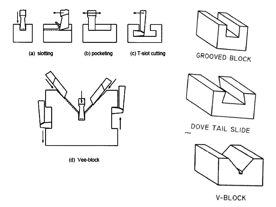
Operations performed on Shaper Machine
The cutting tool reciprocates in horizontal direction while the work is fed towards the tool thus removing material on each stroke. In case of shaping, the cutting force acts parallel to the work piece support.

18
The tool post has been turned at an angle so that side of the material can be machined thus making vertical shaping.

19
The tool post is kept vertical & the top slide is slowly fed into the material so that a ‘rack’ can be machined for a rack and pinion gear system.

20
it calls for simultaneous operation of horizontal table feed as well as vertical hand feed of the cutting tool. It can be performed only by a very skilled operator.

24
Cutting Speed It is defined as the no. of cutting strokes, which the ram makes per minute. In shaper, average cutting speed is considered as no cutting takes place in return stroke. Harder the metal or deeper the cut, slower is the cutting speed. Softer the metal or lighter the cut, higher is the cutting speed.

25
Feed

26
Depth of Cut

27
Machining Time

28
Process Capabilities Shaping process involves short setup time and uses relatively inexpensive tools. Shaping is often used for emergency production of gears, splined shafts, racks etc. It is often possible to produce one or two such parts in a shaper in less time than is required merely to set up for production on other alternative equipment with a higher output rate.

29
The cost per cubic cm of metal removed by shaping may be as much as five times that for removal by milling or broaching. This confines shaping to small quantity production as in tool rooms or model shops.

30
Shaper Mechanisms Hydraulic Shaper Mechanism
This technique operates by pumping hydraulic oil from reservoir (K) through the pump (P) to a cylinder (C) from two opposite sides (C1) or (C2). The machine table is connected to the rod of the cylinder (R).
 through the pump (P) to a cylinder (C) from two opposite sides (C1) or (C2). The machine table is connected to the rod of the cylinder (R).")
31
To obtain the cutting stroke, the valve (V1) is opened while the other valve (V2) is closed as described by the dotted position of the lower piston. The pumped oil is fed to the cylinder through its right valve (V1). This pushes the piston (S) causing the cutting action in the direction described by the figure.
. This pushes the piston (S) causing the cutting action in the direction described by the figure.")
32
This motion continues until socket (d1) hits the lever (L) at the right position making it to rotate around its center (O). This pushes the piston rod (r) to the new position described in the figure by the continuous line. This allows the oil to be pumped through the valve (V2) through the other end (C2) causing the return stroke to start.
 to the new position described in the figure by the continuous line. This allows the oil to be pumped through the valve. (V2) through the other end (C2) causing the return stroke to start.")
33
This continues until the lever (L) hits the left socket (d2) opening the right valve (V1) and closing the left one allowing another cutting stroke. The rapid return speed is obtained since there is a reduction in the cylinder area due to the existing of the piston rod.

35
Crank & slotted link quick return Mechanism
The crank AB (of adjustable length R) rotates with a uniform angular speed. The crank pin B is in the shape of a die block which is free to slide inside the slot in the slotted lever OBC. This slotted lever is pivoted at O and the other end C is connected to the ram by a short link arm.
 rotates with a uniform angular speed. The crank pin B is in the shape of a die block which is free to slide inside the slot in the slotted lever OBC. This slotted lever is pivoted at O and the other end C is connected to the ram by a short link arm.")
36
When the crank AB rotates clockwise from position AB1 to AB2, the ram moves forward from left to right and when it rotates from position AB2 to AB1 the ram returns back to its original position. The further it is away from the centre of bull wheel, the longer is the stroke.

37
The time taken to complete forward stroke is proportional to angle α.
The return stroke is completed in less time which is proportional to angle β.

38
shaper mechanism.mp4

39
Whitworth Quick Return Mechanism
The crank OC is fixed and OQ rotates about O. The slider slides in the slotted link and generates a circle of radius CP. Link 5 connects the extension OQ provided on the opposite side of the link 1 to the ram (link 6).
.")
40
The rotary motion of P is taken to the ram R which reciprocates.
The angle covered during cutting stroke from P1 to P2 in counter clockwise direction is α or θ. During the return stroke, the angle covered is 2θ or β.

41
Whitworth Mechanism whitworthův mechanismus.mp4
Douglas Metal Shaper.Mp4.mp4

Similar presentations


>")