Download presentation
Presentation is loading. Please wait.

1
Senior Design Project Cirrus Design AEM 4331 Jon Anderson Mike Asp Kyle Bergen Ejvin Berry Cody Candler Jim Forsberg Mike Gavanda Alex Messer Dan Poniatowski

2
Agenda Introduction –Problem Overview –Requirements and goals –Program Plan Wing Trade Study Overview and Results Cargo Pod Design Overview and Results FMEA and Conclusion

3
Problem Overview Wing Trade Study –Improve wing performance and design high lift devices that maintain current stall performance. Cargo Pod Design –Design a cargo pod for the SR-22 that is able to carry two golf bags or two pairs of skis.

4
Wing Trade Study Requirements –New wing design shall increase lift by 300 pounds at all flight conditions. –High lift devices shall allow for the same stall speed as the current wing. Goals –No increase in drag –No increase in wing area –No increase in wingspan

5
Cargo Pod Design Requirements –Pod shall not interfere with the safe operation of the SR-22. –Pod shall be designed for optimum user utility. Goals –Less than 15% drag increase –Pod is capable of holding two golf bags or two pairs of skis. –Pod is stylish and easy to use

6
Program Plan

7
Program Plan Continued

9
Budget This design project does not have a build component No wind tunnel tests were done due to the Reynolds number discrepancy The project was completed on a total budget of zero

10
Wing Trade Study Requirements: Lift 300 more pounds of payload Fly at same cruise speed and stall speeds Derived requirements: Increase wing loading during cruise and slow flight Increase L/D at cruise Increase maximum Cl near stall to accommodate 300 extra pounds Results: Our methods failed to accomplish the goals

11
Belly Pod design Requirements: 2 sets of skis with equipment 2 sets of golf clubs (with drivers) Fishing poles Results: Have a design that meets these goals
 Fishing poles Results: Have a design that meets these goals")
12
CFD (In)Validation
Validation")
13
Simulation in FlowWorks Goal: Reproduce data found from wind tunnel test in FlowWorks Method: Build the same bodies that were tested in the wind tunnel in SolidWorks Simulate various ways of building the same object Simulate the same angles of attack and airspeeds used in the wind tunnel Test different mesh resolutions Compare resulting forces

14
Models Horizontal Return Tunnel:Closed Return Tunnel:

15
Pressure differences between models

16
Varying Reynolds Number Re = 3.0x10 5

17
Re = 3.4x10 5 Varying Reynolds Number

18
Re = 4.0x10 5 Varying Reynolds Number

19
Varying Mesh Resolution

22
Wing Process Flowchart

23
Baseline Wing Create a baseline wing for comparison Base it off of the SR-22 specifications Root chord: 61.25 inches Tip chord: 31.5 inches Half-span: 215.5 inches StationThicknessCamberMax thickness Location Max Camber Location Root18.5%4%40%45% Mid 115.5%3%40%45% Mid 2-1degree droop 15.5%3%40%45% Tip-1.5 deg droop 13.7%2%40%45%

25
Cruise wing optimization Guidelines (derived requirements) Maintain the same or lower drag Increase lift by 300 pounds Maintain the same or lower surface area, and maintain the same or lower wingspan - improve lift to drag ratio and wing loading of the baseline wing. Note, only considering cruise conditions at the moment.

26
Airfoil Selection Two different airfoil shapes were investigated in xfoil in order to determine the effect of camber on L/D and maximum Cl.

27
Airfoil Selection Curves made in x-foil. Both plots are of airfoil 1 with varying cambers at Re=6 million

28
Airfoil selection Curves made in x-foil. Both plots are of airfoil 2 with varying cambers at Re=6 million

31
Shapes of Airfoils

32
Low Chamber -Low Drag-High Speed-Thin Wing Section-Good For Racing aircraft, Fighters and Interceptor Planes. Deep Chamber-High Lift-Low Speed-Thick Wing Section-Good For Transport, Freighters and Bomber Planes. Low Lift-High Drag-Reflex Trailing Edge Wing Section. Very Little Movement Of Center Pressure. Good Stability. Symmetrical (Cambered Top and Bottom) Wing Section-Similar To Above. GA(W)-1 Airfoil-Thicker For Better Structure and Lower Weight-Good Stall Characterististics- Chamber Is Maintained Farther Rearward Which Increases Lifting Capability Over More Of The Airfoil and Decreases Drag.
 Wing Section-Similar To Above. GA(W)-1 Airfoil-Thicker For Better Structure and Lower Weight-Good Stall Characterististics- Chamber Is Maintained Farther Rearward Which Increases Lifting Capability Over More Of The Airfoil and Decreases Drag..")
33
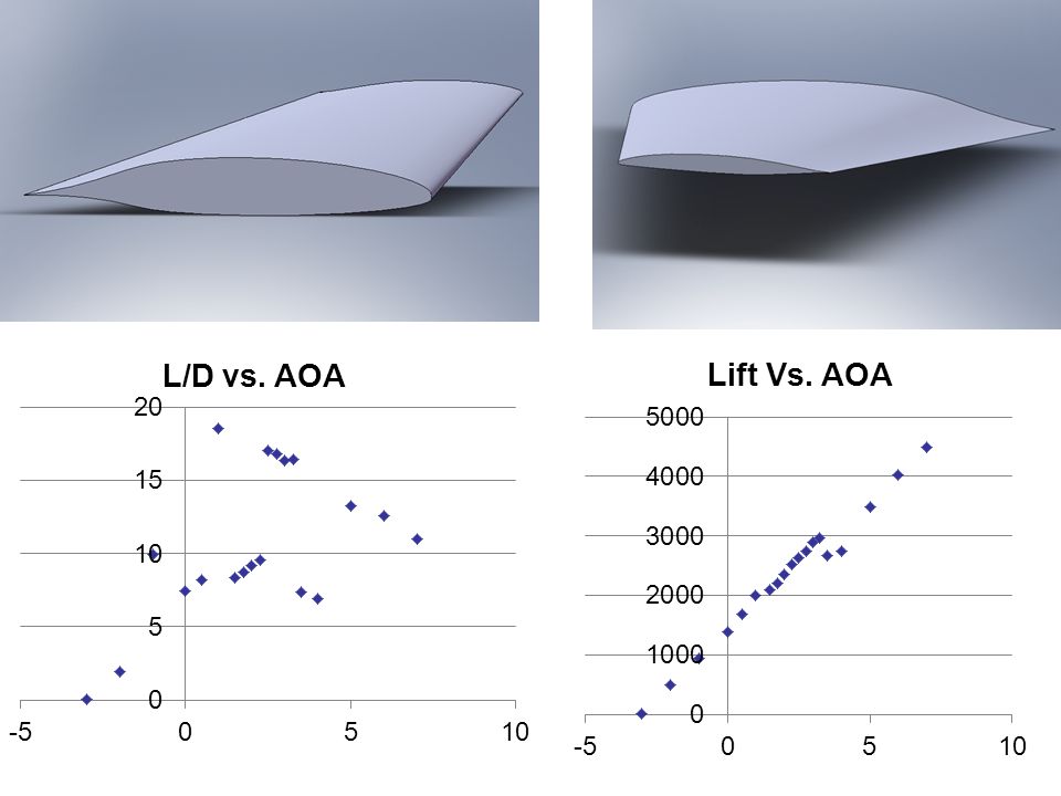
Root: ARA-D 6% Tip: N-14

34
AOALIFTDRAG 27880.44524.86 37989.5721.219 49079250.788 AOALIFTDRAG 27857.322799.5637 37940.8051138.369 49039.39883.4961 Airfoil: Root: ARA-D 6% Tip: N-14 Actual

35
Root: ARA-D 10% Tip: N-14

36
Actual AOALIFTDRAG 23924.37305.341 34240.54362.769 44685.58156.189 AOALIFTDRAG 23911.323442.1135 34215.743584.2046 44663.271482.6581 Airfoil: Root: ARA-D 10% T: N-14

37
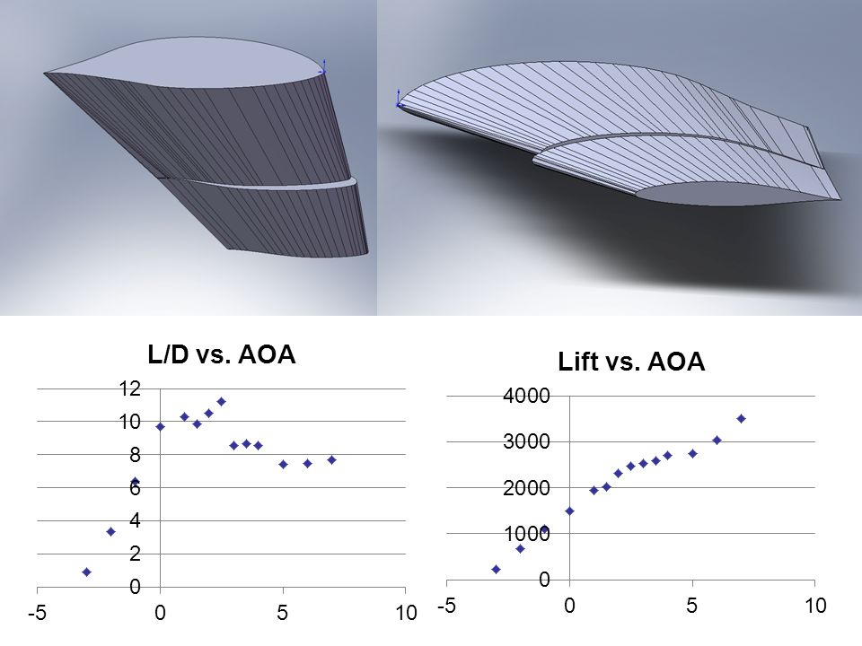
Root: GOE 619AT18.5 Tip: S8035 for RC aerobatic 14% thick

38
AOALIFTDRAG 02814.83329.742 13321.04362.867 23777.61150.541 33999.73327.162 44443.9177.991 Airfoil: Root: GOE 619 Tip: S8035 for RC aerobatic 14% thick AOALIFTDRAG 02814.83329.742 13314.201420.7719 23770.055282.286 33977.126536.0433 44427.644387.7925 ACTUAL

39
Root: FX 66-182 Tip: FX 63-137 13.7%

40
Actual AOALIFTDRAG 02784.55300.95 13519.3120.135 24051.8687.3311 34310.62161.712 44698.07-29.0639 AOALIFTDRAG 02784.55300.95 13516.667181.537 24046.344228.6858 34296.249387.0908 44688.653298.7277 Airfoil: Root: FX 66-182 Tip: FX 63-137 13.7%

41
Actual AOALIFTDRAG 23127.13312.689 33441.4581.1619 43888.9117.683 AOALIFTDRAG 23114.312421.6338 33432.486261.1622 43871.218388.6723 Airfoil 2: Root: FX 66-182 Tip: FX 63-137 13.7% SP4.0

42
Leading edge slats accelerate the air in the funnel shaped slot (venturi effect) and blow the fast air tangentially on the upper wing surface through the much smaller slot. This "pulls" the air around the leading edge, thus preventing the stall up to a much higher angle of attack and lift coefficient (approximately 30 degrees). It does this by picking up a lot of air from below, where the slot is large, the disadvantage of the leading edge slat is that the air accelerated in the slot requires energy which means higher drag. As the high lift is needed only when flying slowly (take-off, initial climb, and final approach and landing) the temptation for the designer is to use a retractable device which closes at higher speeds to reduce drag. Changing from a plain airfoil to an airfoil with flaps we have created an increase of curvature of the airfoil which gives part of the extra lift, but we have also created a depression, a low pressure near the trailing edge, which sucks the air over the upper part of the airfoil and helps it to overcome the forces that are present when the air flow has to come around the nose of the wing. It is like a pull acting from the trailing edge and pulling the air around the leading edge, thus preventing separation
. It does this by picking up a lot of air from below, where the slot is large, the disadvantage of the leading edge slat is that the air accelerated in the slot requires energy which means higher drag. As the high lift is needed only when flying slowly (take-off, initial climb, and final approach and landing) the temptation for the designer is to use a retractable device which closes at higher speeds to reduce drag. Changing from a plain airfoil to an airfoil with flaps we have created an increase of curvature of the airfoil which gives part of the extra lift, but we have also created a depression, a low pressure near the trailing edge, which sucks the air over the upper part of the airfoil and helps it to overcome the forces that are present when the air flow has to come around the nose of the wing. It is like a pull acting from the trailing edge and pulling the air around the leading edge, thus preventing separation.")
43
Drawback to having slots Slots naturally put a penalty on the aircraft they are used on. This is because at cruise airspeed they create some drag compared to a non-slotted wing and so reduce cruising speed.

44
Solution to drawback and difference between slots and slats One way to reduce the cruise drag of slots is to make them retractable. These are known as leading edge slats. Slats work in the same way as slots but slats retract at higher speeds when they are not needed. Slats, in turn, are heavier and more complex than slots.

45
Plain Flap Plain flaps are a hinged section of the wing but move only (and jointly) downward usually to fixed predetermined positions, each position providing varying degrees of increased lift coefficient and increased drag coefficient that the designer thinks is appropriate. For instance – for one particular aircraft – at 5° deflection there is a good increase in CL with only slight increase in drag. At 15° the drag increase starts to equate with the CL increase whereas at 25° or 30° the increase in drag is much greater than the increase in CL; at 45° the flap is starting to act as an airbrake.

47
Plain Flaps

48
Actual AOA of 13 Graph of Actual SP4.0 SP0.0 FLAP ANGLELIFTDRAGLIFTDRAG 30660.96224.1119609.14633.8924 35663.97141.4389679.207-3.09116 40767.984-12.5116747.167-5.22885 FLAP ANGLELIFTDRAGLIFTDRAG 30638.5976172.178585.9095311.4183 35637.6317189.7378662.4943328.3108 40751.1151160.5679729.1934325.4167

49
Plain Flaps and Slots

50
Graph of Actual Actual SP4.0 SP0.0 FLAP ANGLELIFTDRAGLIFTDRAG 30591.342-1.9466716.464-11.9433 35599.4481.05206735.226-8.81165 40630.24613.7779781.112-9.72881 FLAP ANGLELIFTDRAGLIFTDRAG 30576.6238147.4381700.7877149.5321 35583.8475144.3474718.3644156.8041 40610.9935144.8869763.2807166.2325

51
Modified Slot

52
Actual SP0.0 SP4.0 Graph of Actual FLAP ANGLELIFTDRAGLIFTDRAG 30508.99231.6069669.4963.79578 35488.24731.2781667.36415.1514 40566.02141.672692.93819.2246 FLAP ANGLELIFTDRAGLIFTDRAG 30488.8365625145.2951651.483154.3023 35468.6972194140.3081646.8512164.8873 40542.1397581167.931670.8534174.609

53
Modified Slot 1

54
Actual SP4.0 SP0.0 Graph of Actual FLAP ANGLELIFTDRAGLIFTDRAG 30650.8660.980592724.891-14.3086 35582.00511.6035684.9185.87951 40644.08225.4157696.1699.092678 FLAP ANGLELIFTDRAGLIFTDRAG 30633.9638147.3685709.5308149.1231 35564.478142.2287666.041159.8018 40621.8569169.6512676.2808165.4636

55
Modified Slot 2

56
Actual SR4.0 SP0.0 Graph of Actual FLAP ANGLELIFTDRAGLIFTDRAG 30643.549-3.11468735.284-17.1038 35668.6363.61605709.8630.159419 40682.7418.9116754.024-3.19855 FLAP ANGLELIFTDRAGLIFTDRAG 30627.7555314141.7322720.2862148.7375 35650.6854684153.9337691.6334159.8398 40663.2377186162.2665735.4179166.5019

57
Highest Lift with Slots LIFTDRAG 720.2862148.7375 691.6334159.8398 735.4179166.5019 Modified Slot 2Plain Flaps and Slots LIFTDRAG 700.7877149.5321 718.3644156.8041 763.2807166.2325

58
Baseline wing with plain flap

60
Baseline wing with plain flap and slots

62
Baseline wing with plain flap and slots mod 2

63
Fowler flap study 1 non-slotted fowler design Need track system Most increase in lift 2 slotted fowler flap designs Can use offset hinge Less increase in lift

64
Non-slotted fowler flap Provides the highest increase in surface area Requires largest movement of flap

65
Slotted fowler flap Doesn’t provide as much increase in wing area Doesn’t require as much movement

66
Non-slotted flap design from “AERODYNAMIC CHARACTERISTICS OF A WING WITH FOWLER FLAPS INCLUDING FLAP LOADS, DOWNWASH, AND CALCULATED EFFECT ON TAKEOFF”, Platt, Robert C, Langley Research Center, 1936, document ID: 19930091607

67
Non-slotted flap design Optimum position of leading edge of flap is X=c, Y=-.025c Optimum flap deflection angle is 40 degrees for Reynolds number of 300,000 Note: optimum position is generally true for most airfoil shapes, but optimum angle isn’t as general, as it also depends on the flap shape too.

68
Non-slotted flap design 30% of the chord at all stations 104 inches long, which is 48% span of wing (including the portion inside fuselage) 30 degrees deflection, hedging on safety against uncertainty in flow separation Results using sea level conditions at 60 knots: AOA 10, Cl =.55, produces 844.2 pounds of lift AOA 13, Cl =.52, produces 899.8 pounds of lift, has severe flow seraration
 30 degrees deflection, hedging on safety against uncertainty in flow separation Results using sea level conditions at 60 knots: AOA 10, Cl =.55, produces pounds of lift AOA 13, Cl =.52, produces pounds of lift, has severe flow seraration")
69
Slotted flap design guidelines Optimum position of flap leading edge depends primarily on the shape of the slot, and is best determined by experiment In general, moves inward when lip is increased but is generally about.01c forward of lip Usually a slot opening on the order of.01c or slightly more is best. Best Cl’s are achieved using flaps with a wing shape. Avoid flaps with blunt leading edge. from “Theory of wing sections”, Ira H. Abbott and Albert E. von Doenhoff, p. 212-213. Dover Publications, NY, 1959.

70
Slotted flap design Two different shapes of slots with different flap shapes. The one on the right has a small lip with max cl=2.57, the one on the left is a smooth slot with max cl=2.35.

71
Slotted flap design On the left is a slot with a larger lip and with a maximum Cl=2.65. On the right is a plot of the effect slot entry radius has on maximum Cl. from “Wind-tunnel investigation of an NACA 23012 airfoil with various arrangements of slotted flaps”, Wenzinger, Carl J; Harris, Thomas A, Langley Research Center, 1939, ID: 19930091739

72
Slotted flap design 1 30% of the chord at all stations 104 inches long, which is 48% span of wing (including the portion inside fuselage) 30 degrees deflection Results using sea level conditions at 60 knots: AOA 10, Cl =.6, produces 840.5 pounds of lift AOA 13, Cl =.7, produces 980.5 pounds of lift
 30 degrees deflection Results using sea level conditions at 60 knots: AOA 10, Cl =.6, produces pounds of lift AOA 13, Cl =.7, produces pounds of lift")
73
Slotted flap 1 with slot in flap 30% of the chord at all stations 104 inches long, which is 48% span of wing (including the portion inside fuselage) 30 degrees deflection Results using sea level conditions at 60 knots: AOA 10, Cl =.6, produces 841.5 pounds of lift AOA 13, Cl =.8, produces 1125.4 pounds of lift
 30 degrees deflection Results using sea level conditions at 60 knots: AOA 10, Cl =.6, produces pounds of lift AOA 13, Cl =.8, produces pounds of lift")
74
Slotted flap design 2 30% of the chord at all stations 104 inches long, which is 48% span of wing (including the portion inside fuselage) 30 degrees deflection Results using sea level conditions at 60 knots: AOA 10, Cl =.63, produces 883 pounds of lift AOA 13, Cl =.75, produces 1050 pounds of lift
 30 degrees deflection Results using sea level conditions at 60 knots: AOA 10, Cl =.63, produces 883 pounds of lift AOA 13, Cl =.75, produces 1050 pounds of lift")
75
Slotted flap 2 with slot in flap 30% of the chord at all stations 104 inches long, which is 48% span of wing (including the portion inside fuselage) 30 degrees deflection Results using sea level conditions at 60 knots: AOA 10, Cl =.65, produces 916 pounds of lift AOA 13, Cl =.654, produces 921 pounds of lift
 30 degrees deflection Results using sea level conditions at 60 knots: AOA 10, Cl =.65, produces 916 pounds of lift AOA 13, Cl =.654, produces 921 pounds of lift")
76
Comparison Non-slotted flap was calculated to have the least lift. Slotted flap 1 produced more lift with a slot in the flap at AOA 13 than slotted flap 2. Slotted flap 2 produced more overall lift without a slot in the flap than slotted flap 1. Conclusion: Design 2 is better, but the slot on the flap isn’t optimized.

77
Further investigation Distances between locations are about 1.8% chord length

78
Further investigation The slot in flap used in comparison

80
Flapperon Study

81
FLAPPERON DESIGN

82
DIMENSIONS OF FLAPPERON

83
COSTS / BENEFITS COSTS –Increased drag when compared to non- deployed flapperons. Possibly caused by flow separation due to gap between wing and flapperon when deployed. –Could be difficult to work mechanically with the pulley system in place now. –Hard to control during landing due to adverse yaw effects.

84
BENEFITS –Increase camber during landing. –Increase lift due to increased camber. Optimal position is with flapperons deployed 40°

85
Cargo Pod Design

86
Individual Report Ejvin Berry 96 hours Tasks –Initial Aerodynamics Optimization –Quick Prototype Modeling –Final Concept Modeling

87
Cirrus SR22 Cargo Pod

88
Cargo Pod Guidelines With 2 passengers (including pilot), 4 hours of fuel, carry one of the following: 2 sets of skis with equipment –Required volume of 12in x 6in x 77 in 2 sets of golf clubs (with drivers) –Required volume of 35in x 11in x 50in Minimum 8” offset from firewall –Exhaust Clearance
, 4 hours of fuel, carry one of the following: 2 sets of skis with equipment –Required volume of 12in x 6in x 77 in 2 sets of golf clubs (with drivers) –Required volume of 35in x 11in x 50in Minimum 8 offset from firewall –Exhaust Clearance")
89
Pod on Fuselage

90
Clearance/ Tail Strike Envelope

91
Bottom View

92
Attachment View

93
Front Fairing (2) Rear Fairing
 Rear Fairing")
94
Conclusions Demonstrates –Practicality Meets required tasks, loads –Ease of Operation Location specific, ease of access. –Aesthetic Quality –Aerodynamics

95
Recommendations Study feasibility of manufacturing contoured pod surfaces to mesh with fuselage. –Increased capacity –Fit CG envelope better –Aerodynamics Improved

96
Attachment Method Design

97
Attachment Brackets Rough Solid Works Models

98
Front Attachment to Longerons

99
Plugs for Non-use

100
Rear Longeron Attachment

101
Example of floor with Longerons

102
Screw holes Screw Holes are 3/8 in. in diameter. Plug screw in to holes when Pod is not attached

103
Attachment from Belly to Pod

104
Piece from Pod to Belly

105
Belly/Pod attachment The Belly to Pod piece screws into front longeron attachment. Pod to belly piece is embedded into Fiberglass Pod. Belly/Pod pieces bolt together

106
Pod Size Goals Two golf bags with clubs Two pares of downhill skis Minimize drag Clear ground on fully loaded landing Clear ground on tail strike Easy to remove 3:37 AM

107
Solid works attached Pod model 3:37 AM

108
Clearance 3:37 AM

109
Solid Works model 3:37 AM

110
Pod Ground Clearance 3:37 AM

111
Pod wheel Clearance 3:37 AM

112
Golf Bag Width10 in Height Bag34 in Height with clubs50 in Golf Bag Size 3:37 AM

113
Golf Bag Clearance 3:37 AM

114
Skis Length (cm)173180 Side cut tip(mm)130135 Waist (mm)9699 Tail (mm)124125 Weight (g for one ski)19702210 http://www.salomonski.com/us/products/XW-Sandstorm-1-1-1-788918.html 3:37 AM
 Side cut tip(mm) Waist (mm)9699 Tail (mm) Weight (g for one ski) :37 AM")
116
Reference points of the front and back of the cargo pod while attached (Figure 6-1 out of the Cirrus Manual)
")
117
C.G. of the aircraft with the pod attached Sample Loading Pilot – 200 lbs Passenger – 200 lbs Fuel – 486 lbs (full tank) Cargo Pod – 100 lbs Center of Gravity Limits No Luggage Luggage – 25 lbs Luggage – 50 lbs C.G. of pod located at FS 148.0 Moment Limits
 Cargo Pod – 100 lbs Center of Gravity Limits No Luggage Luggage – 25 lbs Luggage – 50 lbs C.G. of pod located at FS Moment Limits.")
118
Streamlines around the cargo pod Altitude: 4000 ft Velocity: 185 KTAS

119
Pressure Distribution on Pod at 178 KTAS and altitude 12,000 ft Total Drag = 68.934 lbs

120
Pressure Distribution on the pod at: 8000 ft 185 KTAS 25 mph crosswind Crosswind Total Drag (flight direction) = 83.750 lbs Force from crosswind = 20.494 lbs
 = lbs Force from crosswind = lbs")
121
Effects of Cargo Pod on Drag During Cruise Drag (lbs) Altitude (ft) Conditions Data taken with engine running at 2700 rpm CR-22 engine has 310 hp @ 2700 rpm Drag calculated on aircraft using Drag = T R = P R / V ∞ Drag calculated on cargo pod from FloWorks Results Cargo pod increased drag on aircraft by 18–19% Abnormally high since area of cargo pod is much smaller than the aircraft Maybe an error in SolidWorks?
 Altitude (ft) Conditions Data taken with engine running at 2700 rpm CR-22 engine has rpm Drag calculated on aircraft using Drag = T R = P R / V ∞ Drag calculated on cargo pod from FloWorks Results Cargo pod increased drag on aircraft by 18–19% Abnormally high since area of cargo pod is much smaller than the aircraft Maybe an error in SolidWorks")
122
Velocity Reduction of SR-22 due to the Effects of the Cargo Pod Velocity (ft/s) Altitude (ft) At 310 hp and 2700 rpm The engine outputs P max =170,500 ft·lb/s To calculate velocity with Pod attached, V = (% PWR x P max ) / D tot Results 15-16% decrease in velocity with the pod attached Seems way to large Error in SolidWorks?
 Altitude (ft) At 310 hp and 2700 rpm The engine outputs P max =170,500 ft·lb/s To calculate velocity with Pod attached, V = (% PWR x P max ) / D tot Results 15-16% decrease in velocity with the pod attached Seems way to large Error in SolidWorks")
123
Maximum Speed with Cargo Pod Attached Conditions: Get to a location as fast as possible 4 hours endurance 81 gallons of usable fuel Weight: 3400 lbs Take off from sea-level No wind Results w/o Pod: Optimal Cruise Altitude: 12000 ft Fuel to taxi: 1.5 gal Fuel to climb: 4.4 gal Fuel to cruise: 59.8 gal @ 15.4 GPH 45 min IFR fuel reserve: 9.8 gal Airspeed: 178 KTAS Range: 785 nautical miles Adjusted results for attached cargo pod: Airspeed: 151.3 KTAS (15% reduction) Range: 640 nautical miles (18% reduction) Endurance of 4.3 hours
 Range: 640 nautical miles (18% reduction) Endurance of 4.3 hours")
124
Maximum Range with Cargo Pod Attached Conditions: Maximum range 81 gallons of useable fuel Weight: 3400 lbs Takeoff from sea level No wind Results w/o Pod: Optimal Cruise Altitude: 14000 ft Fuel to taxi: 1.5 gal Fuel to climb: 5.3 gal Fuel to cruise: 57.8 gal @ 11.3 GPH 45 min IFR fuel reserve: 9.8 gal Airspeed: 169 KTAS Range: 1006 nautical miles Adjusted results for attached cargo pod: Airspeed: 143.7 KTAS (15% reduction) Range: 850 nautical miles (16% reduction) Endurance of 5.8 hours
 Range: 850 nautical miles (16% reduction) Endurance of 5.8 hours")
125
Conclusions Location of the pod is limited due to the exhaust at the firewall and the tail strike on the landing Due to the restriction of the center of gravity of the cargo pod (FS 148.0) a weight of at least 25 lbs must be added to the luggage compartment for the SR-22 to be safe to fly Drag on the cargo pod seems abnormally high, maybe due to miscalculation in SolidWorks When cargo pod is attached, it increases the drag of the SR-22 by 18-19% Due to the large drag increase, the pod also decreases the velocity of the SR-22 by 15-16% The maximum range of the SR-22 with a full tank of fuel and the cargo pod attached is approximately 850 miles
 a weight of at least 25 lbs must be added to the luggage compartment for the SR-22 to be safe to fly Drag on the cargo pod seems abnormally high, maybe due to miscalculation in SolidWorks When cargo pod is attached, it increases the drag of the SR-22 by 18-19% Due to the large drag increase, the pod also decreases the velocity of the SR-22 by 15-16% The maximum range of the SR-22 with a full tank of fuel and the cargo pod attached is approximately 850 miles")
126
Failure Modes and Effects Analysis Enviromental Impact

127
ProblemProbabilitySeverityMitigation High Lift Device Flutter due to failureLowHighPull Parachute. High Lift Device Flutter due to aerodynamicsMediumHighTest for natural frequencies. Avoid frequencies of prop and install dampening. Cable/Mechanical FailureLowHighPull Parachute. High Lift Device Extension/Retraction FailureLow Install mechanical indicator to inform pilot. Spin EntryMedium Install warning placards and mandate anti-spin pilot training. High Lift Device DetachmentLowHighDesign fasteners to release when a partial failure occurs. Pull Parachute. IcingHighVariesIncorporate existing deicing equipment into new design. Collision DamageMedium Reinforce leading edge. Pull Parachute. Wing DetachmentLowVery HighPull Parachute. Internal Fuel LeakLowMedium Install fluid detector and warning device. Instruct pilot to deactivate electronics and land immediately. External Fuel LeakLow Instruct pilot to land immediately. Lightning StrikeMedium Install dissipating mesh in the wing and high lift devices. Heat DamageMediumLowList warnings in Pilot's Operating Handbook. ProblemProbabilitySeverityMitigation Pod hits the groundMediumLowFasteners designed to shear off and release pod. Partial Attachment FailureLowHighRemaining attach points designed to shear off. Foreign Object CollisionMediumLowReinforce the nose of the pod. Front End OverheatingHighMediumAttach a metal heat sheild to the nose. High G FailureMediumHighDesigned to withstand a 4G manuever. CG Out of Balance Due to LoadingHigh Warn the pilot in the Pilot's Operating Handbook and install placards.

Similar presentations


Validation.>")


