Download presentation
Presentation is loading. Please wait.

1
Speed control of stepper motor using microcontroller 8051
Minor project Review 1 B. Tech in Electrical Engineering 7th semester Guided by: Prepared by: Ms. Monika Sharma Akshay Patel(07BEE072) Rohan Shah (07BEE075)
 Rohan Shah (07BEE075)")
2
Contents: Introduction to stepper motor Fundamentals of operation
Characteristics Types of stepper motor Circuit diagram Components to be used Regulator IC 7812 Microcontroller 8051 Driver IC ULN2003A Applications Conclusion References

3
Introduction: A stepper motor (or step motor) is a brushless, synchronous electric motor that can divide a full rotation into a large number of steps. Stepper motors are similar to switched reluctance motors (which are very large stepping motors with a reduced pole count, and generally are closed-loop commutated.)
 is a brushless, synchronous electric motor that can divide a full rotation into a large number of steps. Stepper motors are similar to switched reluctance motors (which are very large stepping motors with a reduced pole count, and generally are closed-loop commutated.)")
4
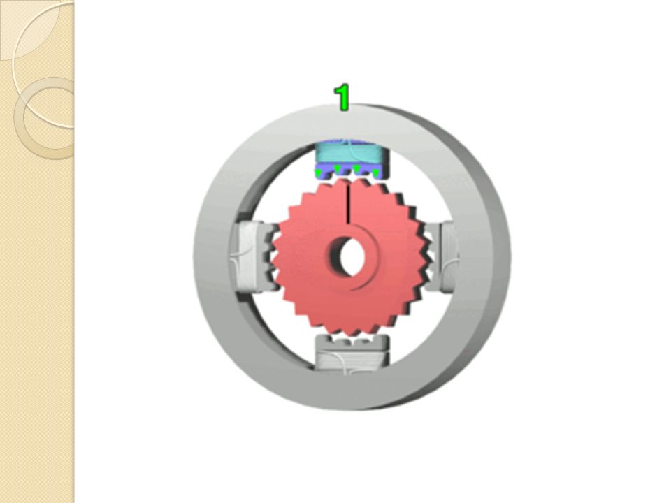
Fundamentals of operation
Stepper motors operate differently from DC brush motors, which rotate when voltage is applied to their terminals. Stepper motors, on the other hand, effectively have multiple "toothed" electromagnets arranged around a central gear- shaped piece of iron. The electromagnets are energized by an external control circuit, such as a microcontroller. To make the motor shaft turn, first one electromagnet is given power, which makes the gear's teeth magnetically attracted to the electromagnet's teeth. When the gear's teeth are thus aligned to the first electromagnet, they are slightly offset from the next electromagnet. So when the next electromagnet is turned on and the first is turned off, the gear rotates slightly to align with the next one, and from there the process is repeated. Each of those slight rotations is called a "step," with an integer number of steps making a full rotation. In that way, the motor can be turned by a precise angle.

6
Stepper motor characteristics
Stepper motors are constant power devices. As motor speed increases, torque decreases. (most motors exhibit maximum torque when stationary, however the torque of a motor when stationary is of little use, torque is more important when the motor is actually spinning) The torque curve may be extended by using current limiting drivers and increasing the driving voltage (sometimes referred to as a 'chopper' circuit, there are several off the shelf driver chips capable of doing this in a simple manner). Steppers exhibit more vibration than other motor types, as the discrete step tends to snap the rotor from one position to another, (this is important as at certain speeds the motor can actually change direction). This vibration can become very bad at some speeds and can cause the motor to lose torque (or lose direction). The effect can be mitigated by accelerating quickly through the problem speeds range, physically damping (frictional damping) the system, or using a micro-stepping driver. Motors with a greater number of phases also exhibit smoother operation than those with fewer phases (this can also be achieved through the use of a micro stepping drive)
 The torque curve may be extended by using current limiting drivers and increasing the driving voltage (sometimes referred to as a chopper circuit, there are several off the shelf driver chips capable of doing this in a simple manner). Steppers exhibit more vibration than other motor types, as the discrete step tends to snap the rotor from one position to another, (this is important as at certain speeds the motor can actually change direction). This vibration can become very bad at some speeds and can cause the motor to lose torque (or lose direction). The effect can be mitigated by accelerating quickly through the problem speeds range, physically damping (frictional damping) the system, or using a micro-stepping driver. Motors with a greater number of phases also exhibit smoother operation than those with fewer phases (this can also be achieved through the use of a micro stepping drive)")
7
Types of stepper motor There are three main types of stepper motors:[1] Permanent Magnet Stepper (can be subdivided in to 'tin-can' and 'hybrid', tin-can being a cheaper product, and hybrid with higher quality bearings, smaller step angle, higher power density) Hybrid Synchronous Stepper Variable Reluctance Stepper Permanent magnet motors use a permanent magnet (PM) in the rotor and operate on the attraction or repulsion between the rotor PM and the stator electromagnets. Variable reluctance (VR) motors have a plain iron rotor and operate based on the principle of that minimum reluctance occurs with minimum gap, hence the rotor points are attracted toward the stator magnet poles. Hybrid stepper motors are named because they use a combination of PM and VR techniques to achieve maximum power in a small package size.
![Types of stepper motor There are three main types of stepper motors:[1]](http://slideplayer.com/slide/10977655/39/images/7/Types+of+stepper+motor+There+are+three+main+types+of+stepper+motors%3A%5B1%5D.jpg "Permanent Magnet Stepper (can be subdivided in to tin-can and hybrid , tin-can being a cheaper product, and hybrid with higher quality bearings, smaller step angle, higher power density) Hybrid Synchronous Stepper. Variable Reluctance Stepper. Permanent magnet motors use a permanent magnet (PM) in the rotor and operate on the attraction or repulsion between the rotor PM and the stator electromagnets. Variable reluctance (VR) motors have a plain iron rotor and operate based on the principle of that minimum reluctance occurs with minimum gap, hence the rotor points are attracted toward the stator magnet poles. Hybrid stepper motors are named because they use a combination of PM and VR techniques to achieve maximum power in a small package size.")
8
Circuit diagram

9
Components to be used: Step down transformer 230 V/12 V
Regulator IC 7812 Microcontroller AT89C2051 Driver IC ULN2003A Unipolar Stepper motor Resistance, capacitance and LEDs

10
IC 7812 IC 7812 is used for constant 12V d.c output voltage.
Input to the IC is from the output of full wave bridge rectifier Pin-1 is input pin, pin-2 is ground pin and pin-3 is output pin.

11
Microcontroller 8051

12
ULN2003A

13
Applications Computer-controlled stepper motors are one of the most versatile forms of positioning systems. They are typically digitally controlled as part of an open loop system, and are simpler and more rugged than closed loop servo systems. In the field of lasers and optics they are frequently used in precision positioning equipment such as linear actuators, linear stages, rotation stages and mirror mounts. Other uses are in packaging machinery, and positioning of valve pilot stages for fluid control systems. Commercially, stepper motors are used in floppy disk drives, flatbed scanners, computer printers, plotters, slot machines, and many more devices. Some people looking for generators for homemade Wind Turbines found success in using stepper motors for generating power.

14
Conclusion Stepper motor can be operated at different speeds with the help of microcontroller with the precise angle because of the small step angle present in the motor. Also, it can be rotated in different directions: clockwise or anticlockwise. And this can be used for various applications used above

15
References IEEE PAPER: MICROCOMPUTER SPEED CONTROL OF STEPPER MOTOR By C.S.Chen.
16
Thank You…….

Similar presentations


>")

 No.>")


 converts it into mechanical work.>")
 Gurunath Athalye.>")
