Download presentation
Presentation is loading. Please wait.

1
Beam Transport for MW Class FEL Drivers D. Douglas Jefferson Lab

2
Homiletics A sermon is three points, a poem, and a joke: 1.drivers for MW class performance are possible 2.drivers for MW class performance can’t be built yet but the path is clear 3.system integration advice: it’s a LINAC (change the round hole, not the square peg)
")
3
System Paradigm (Prejudice, Obsession) Low peak, high average power FEL driven by SRF ERL it’s elegant it’s in my comfort zone: it’s what I know & like it might just work nobody’s publicly admitted to producing kW-level CW average power with anything else (yet) Consider me the King’s Fool: I will tell you the truth (hopefully with humor). You may ignore it, avoid it, or use it. You may smack me as you will, but it will be the truth…

4
Machine Concept 100 MeV 0.5 A P beam ~50 MW FEL ~2 % P FEL ~ 1 MW SRF linac wiggler/optical cavity dump injector here there be dragons…

5
Examples (the usual suspects) JLab IR Demo FEL 50 MeV 5 mA = 0.25 MW FEL ~ 0.8% P FEL = 0.002 MW footprint: 45 m 6 m JLab IR Upgrade FEL 150 MeV 10 mA = 1.5 MW FEL ~1% P FEL = 0.015 MW footprint: 65 m 6 m These systems provide guidance for design of higher power devices
 JLab IR Demo FEL 50 MeV 5 mA = 0.25 MW FEL ~ 0.8% P FEL = MW footprint: 45 m 6 m JLab IR Upgrade FEL 150 MeV 10 mA = 1.5 MW FEL ~1% P FEL = MW footprint: 65 m 6 m These systems provide guidance for design of higher power devices")
6
Review of Issues/Requirements Management of full 6-d phase space from source to FEL, from FEL to dump Halo Suppression/control of instabilities and other collective effects Beam quality preservation

7
Review: Phase Space Management Transverse –include RF focusing effects –keep envelopes small (instabilities, error sensitivities, halo control) –may need to select/control phase advances to suppress instabilities –CSR control Longitudinal –accelerate long bunch to avoid instabilities; compress length just before wiggler –energy compress during energy recovery –typically must compensate RF waveform curvature (both in bunch length and energy compression) either magnetic or harmonic RF effective; one or other may be help in packaging system –Note: can’t energy recover even harmonic RF (avoid sawtooth waveforms!) –Note: unless you do something special to waveform, must use opposite signs of compaction to compress bunch length and energy (or recover more/less than 180 o apart in RF phase) Status: phase space management is straightforward, but to date has required tunable system (variable quads, sextupoles) and hasn’t been demonstrated at high (kW) powers using harmonic RF
 –may need to select/control phase advances to suppress instabilities –CSR control Longitudinal –accelerate long bunch to avoid instabilities; compress length just before wiggler –energy compress during energy recovery –typically must compensate RF waveform curvature (both in bunch length and energy compression) either magnetic or harmonic RF effective; one or other may be help in packaging system –Note: can’t energy recover even harmonic RF (avoid sawtooth waveforms!) –Note: unless you do something special to waveform, must use opposite signs of compaction to compress bunch length and energy (or recover more/less than 180 o apart in RF phase) Status: phase space management is straightforward, but to date has required tunable system (variable quads, sextupoles) and hasn’t been demonstrated at high (kW) powers using harmonic RF")
8
Review: Halo Management Halo is likely a major limitation to very high powers –halo generation: complex topic poorly understood by ordinary mortals, and thus largely ignored by machine designers (like me) –halo likely largely formed in front end –chunks of it scrape off and melt stuff, irradiate things and make life generally unpleasant. Need well less than 1 A loss at any single point. Current loss is worse for big beam envelopes (beam large, lattice sensitive), small apertures, high currents –Experience in CEBAF, IR Demo, CEBAF-ER suggests C~10 -6, so in ~1 A machine need aperture larger than beam envelope (!!??) Status: unsolved problem, under study - but only at most rudimentary level and at low powers (signal to noise – core beam swamps diagnostic at few mA). Much work needed!
, small apertures, high currents –Experience in CEBAF, IR Demo, CEBAF-ER suggests C~10 -6, so in ~1 A machine need aperture larger than beam envelope (!! ) Status: unsolved problem, under study - but only at most rudimentary level and at low powers (signal to noise – core beam swamps diagnostic at few mA). Much work needed!.")
9
Review: Instabilities & Collective Effects Wakes (beam-induced fields) –keep bunch long until you need it short –shield components Coherent Synchrotron Radiation (CSR) –same approach – don’t compress until you need to, in fact, generalize to say… –keep at least some bunch dimensions well beyond coherence length (so if its short, make it a pancake) –impact is smaller at larger emittance & emittance spec loose for IR FELs, so not as critical as in UV, X-FEL HOM/BBU –HOM suppression by proper SRF system design –feedback stabilization –suppression supported by proper choice of betatron phase non-zero chromaticity may help - phase decoherence across large momentum spread bunch (induced by FEL) decorrelates betatron response to HOM kicks –need to worry about power deposition from propagating modes!!!
 –keep bunch long until you need it short –shield components Coherent Synchrotron Radiation (CSR) –same approach – don’t compress until you need to, in fact, generalize to say… –keep at least some bunch dimensions well beyond coherence length (so if its short, make it a pancake) –impact is smaller at larger emittance & emittance spec loose for IR FELs, so not as critical as in UV, X-FEL HOM/BBU –HOM suppression by proper SRF system design –feedback stabilization –suppression supported by proper choice of betatron phase non-zero chromaticity may help - phase decoherence across large momentum spread bunch (induced by FEL) decorrelates betatron response to HOM kicks –need to worry about power deposition from propagating modes!!!")
10
CSR Simulation * ½ nC: 10 mm-mrad ~15 mm-mrad * JLAB-TN-00-017

11
CSR Simulation * * JLAB-TN-00-017

12
Still Reviewing: Instabilities & Collective Effects Status: –phenomena are pretty well understood & probably manageable –further measurements (esp. CSR, BBU, propagating HOM) and benchmarking of codes needed expect to see BBU when 3 rd module installed in JLab 10 kW FEL Upgrade (rich HOM spectrum, implying low threshold), will be able to more carefully benchmark theory & simulation learn how to build effective feedback systems. –more work on HOM management, feedback, and transport system design needed before very high powers will be achieved motivates move toward lower frequency structures with fewer cells effect of power deposition from propagating modes is not well understood at high powers
 and benchmarking of codes needed expect to see BBU when 3 rd module installed in JLab 10 kW FEL Upgrade (rich HOM spectrum, implying low threshold), will be able to more carefully benchmark theory & simulation learn how to build effective feedback systems. –more work on HOM management, feedback, and transport system design needed before very high powers will be achieved motivates move toward lower frequency structures with fewer cells effect of power deposition from propagating modes is not well understood at high powers.")
13
Review: Beam Quality Preservation Motherhood statements: Be sure to suppress collective effects (CSR, wakes) –make bunch short only where it needs to be short –shielded beamline components –avoid overly strong bending, focusing Control magnitude & impact of errors on beam –magnetic field inhomogeneities have transverse and longitudinal emittance dilution effects ( B/B generates x’ error, couples to (x,x’) through M 12 and M 22 ; couples to ( RF,E) through M 52 ) Status –probably understand magnetostatic effects/seem to be able to control them IR Demo, IR Upgrade, CEBAF-ER all show well-defined beam and rational beam behavior these underscore the need to carefully spec out system components –learning about collective effects wakes, CSR, BBU, space charge (may become issue as bunch charge goes up)
 –make bunch short only where it needs to be short –shielded beamline components –avoid overly strong bending, focusing Control magnitude & impact of errors on beam –magnetic field inhomogeneities have transverse and longitudinal emittance dilution effects ( B/B generates x’ error, couples to (x,x’) through M 12 and M 22 ; couples to ( RF,E) through M 52 ) Status –probably understand magnetostatic effects/seem to be able to control them IR Demo, IR Upgrade, CEBAF-ER all show well-defined beam and rational beam behavior these underscore the need to carefully spec out system components –learning about collective effects wakes, CSR, BBU, space charge (may become issue as bunch charge goes up)")
14
Developing the Technology probably won’t successfully run initial high power (100+ kW) FELs without a tunable driver accelerator probably will be able to run offspring high power systems with a “precast” compact driver – particularly if you commission using a blue-tip wrench (recut pole-pieces, move stuff around) suggests that FEL and driver evolve along matrixed developmental tracks –have a separate operationally flexible & tunable “laboratory (testbed) driver” for each generation of FEL (10 kW (exists), 100 kW, 1 MW). When it works, move FEL to a deployable “field driver” –reduce flexibility of each subsequent field driver (compact 100 kW, very compact 1 MW) –allows separate, controlled development of source, driver accelerator, FEL, and system integration/packaging process
 –allows separate, controlled development of source, driver accelerator, FEL, and system integration/packaging process.")
15
Example System “Family Tree” JLab 10 kW driver & FEL upgraded 10 kW “lab driver” & 100 kW FEL upgraded 100 kW lab driver & 1 MW FEL 100 kW “field driver” & FEL MW field driver & FEL upgrade driver and FEL migrate FEL upgrade FEL migrate FEL upgrade driver

16
Technology Choices Lower RF frequency with fewer cells –“better” HOM spectrum & impedances –bigger apertures –requires lower compaction –allows use of harmonic RF correction of RF waveform simplifies magnetic transport –coax couplers? magnets: electromagnetic for laboratory driver, permanent magnet (PM) for field drivers
 for field drivers.")
17
The “Minimalist” Machine Parameters E injection ~7 MeV 0.5 A (500 MHz, 1 nC) P injection ~ 3.5 MW E full ~100 MeV 0.5 A P accel ~ 46.5 MW, P full ~50 MW FEL = 2% P FEL ~1 MW, p/p out ~ 10% (specifies energy recovery transport) P recovered ~46.5 MW P dumped = P full - P FEL - P recovered = 2.5 MW E dumped = P dumped /I = 5 MeV you recover power, not energy! & should figure out something to do with the 2½ MW!

18
Features of the “Minimalist” Machine Linearized RF –500 MHz fundamental, 1500 MHz 3 rd harmonic SRF 20 MV/m at 500 MHz 5 m active fundamental, probably 8 m real estate 25 MV at 1500 MHz 1 m active harmonic, probably 2 m real estate 10 m of SRF –run ~20 o off crest to provide enough energy compression Injection “somehow” –Beam materializes on linac axis miraculously matched to rest of system beam envelopes = linac acceptance (use RF focusing) long bunch/low momentum spread RF curvature corrected Simplistic phase space management –Accelerator serendipitously provides beam transversely matched (via RF focusing) to mirror-bend achromat (with chicane for bunch length compression) nose-pieces to fix T 566 of chicane? –Two quads, properly placed, match beam to wiggler –Two quads, properly placed, match beam to return arc mirror bend, which, through some undetermined feat of parlor magic, provides proper transverse match to cryomodule for energy recovery whilst its compaction sets the longitudinal match

19
System Concept Major Components: –injector –100 MeV linac (four 500 MHz cavities, two 1500 MHz cavities) –6 dipoles (~10 kG, PM) –4 quads (PM) Integration Overview: –footprint: 13 m 2 m –weight??????? lbs –costif you have to ask… injector wiggler location 500/1500 MHz cryomodule dump

20
fundamental fundamental + 1/9 th 3 rd harmonic in phase fundamental + 1/9 th 3 rd harmonic 120 o out of phase (increases required compaction, can be used to match to compaction) 3 rd harmonic RF
 3 rd harmonic RF")
21
fundamental + 1/4 th 3 rd harmonic 120 o out of phase (makes flat region away from crest) 3 rd harmonic RF
 3 rd harmonic RF")
22
Parting Salvo It’s front end loaded. The injector is definitely not easy –required performance is orders of magnitude higher than prior art: combination of current-charge/bunch-longitudinal emittance, desired cathode lifetime,… –injector footprint & integration (how large, where to locate, how to inject) –operability (come visit JLab, and see what a real man’s injector is all about!) View it as long and skinny. Do not consider a spherical, cubical, conical, ellipsoidal, or otherwise blob-shaped FEL. Its called a “linac” for a reason. –review integration options (put vacuum pipes through bulkheads, etc) –don’t expect technology to conform to prior notions of usage for shipboard volume: transcend the paradigm of the 5” gun mount! And while we’re talking about linacs – do not be fooled about available real estate gradients –e.g. SLAC: 17 MV/m (50 GeV/3 km) – pulsed – by SLEDing. Transients and all. And you don’t want the transients… Don’t expect vastly more from SRF Dump requires work: 100 kW level CW dump at JLab not trivial, 2.5 MW dumps may be very challenging Think carefully about operational cycle: –existing systems take 10s of minutes to go from off to full on –may need to run in an idle (e - on, FEL off) mode when laser ops anticipated
 –operability (come visit JLab, and see what a real man’s injector is all about!) View it as long and skinny. Do not consider a spherical, cubical, conical, ellipsoidal, or otherwise blob-shaped FEL. Its called a linac for a reason. –review integration options (put vacuum pipes through bulkheads, etc) –don’t expect technology to conform to prior notions of usage for shipboard volume: transcend the paradigm of the 5 gun mount. And while we’re talking about linacs – do not be fooled about available real estate gradients –e.g. SLAC: 17 MV/m (50 GeV/3 km) – pulsed – by SLEDing. Transients and all. And you don’t want the transients… Don’t expect vastly more from SRF Dump requires work: 100 kW level CW dump at JLab not trivial, 2.5 MW dumps may be very challenging Think carefully about operational cycle: –existing systems take 10s of minutes to go from off to full on –may need to run in an idle (e - on, FEL off) mode when laser ops anticipated.")
23
Altar Call… 1.drivers for MW class performance are possible 2.drivers for MW class performance can’t be built yet - but the path to MW levels is clear 3.it’s a LINAC! I hope we have some converts! Supported by: ONR, NAVSEA, AFRL, DOE

24
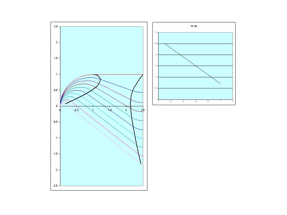
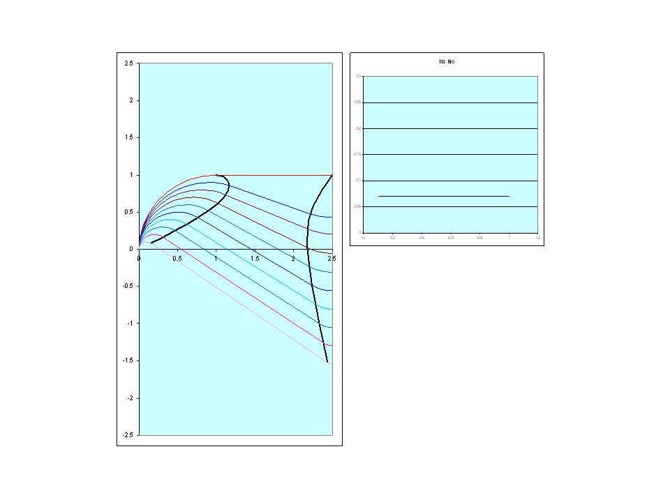
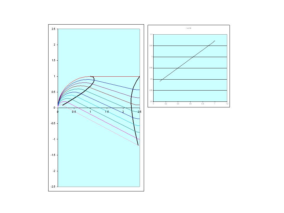
“Everything I’ve Said is Wrong…” Based on paradigm of conventional mirror bend with harmonic RF Can now probably make compaction managed mirror bend – no harmonic RF or higher order corrections needed B A exit pole-face of conventional MBA incoming beam C L A B entrance to MBA “pole face” of extended field region of CMMBA “pole face” of central reverse- bend region of CMMBA d ref dB()dB() B()B() B()B()
dB() B()B() B()B()")
25
Constraints Path length same at all momenta Footprint same at all momenta Solve, at each momentum, for angle and drift length; thereby specify location of poles

29
wiggler SRF linac

Similar presentations


 –Linear.>")


