Download presentation
Presentation is loading. Please wait.

1
5-3-2 The Emitter Follower

2
Learning Objectives: At the end of this topic you will be able to;

3
The Emitter Follower

4
The next section is NOT examinable! It shows you where these relationships come from. If you can follow this, it will help you to understand the way the emitter follower works. The circuit diagram for the simple emitter follower, using an npn transistor, is shown below. VSVS

5
The npn transistor is conducting and so there is a 0.7V drop between the base and the emitter. As a result: VSVS

8
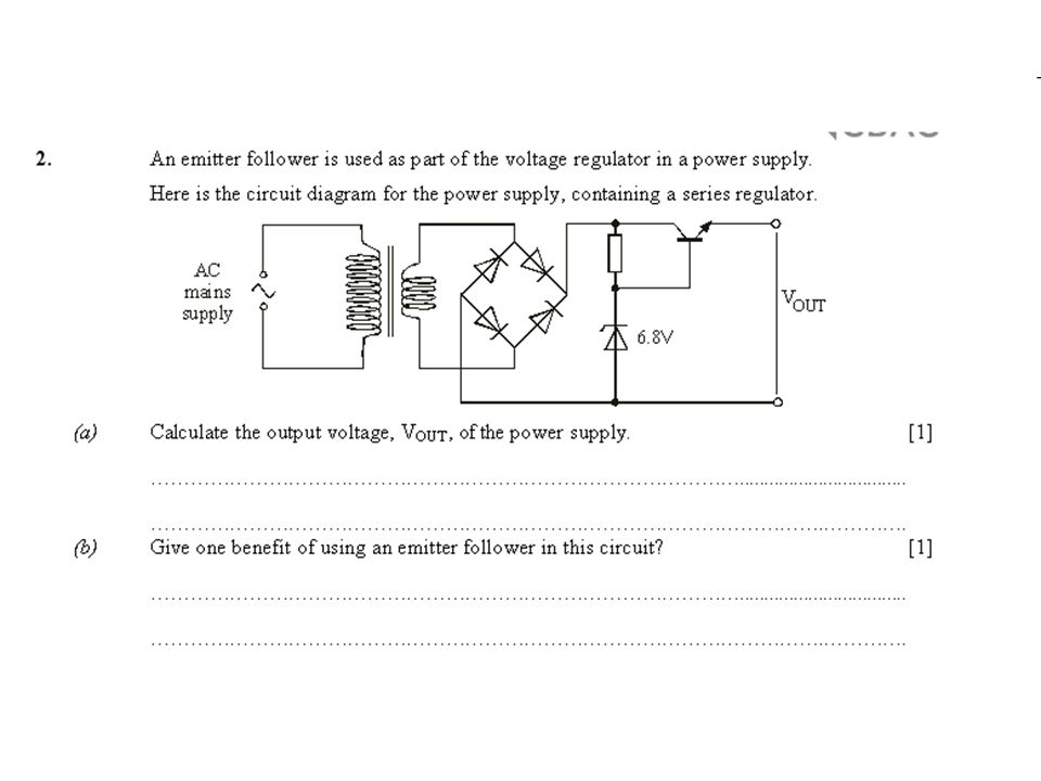
Back to examinable content! Modified voltage regulator Modification 1 – Add an emitter follower to reduce the power ratings of the zener diode and resistor. I out

11
Exercise 2 (The solutions are given at the end of the topic.) In exercise 1, you designed a simple power supply to deliver a current of 1A at a voltage of 10V. Now, an emitter follower is added to reduce power dissipation in the zener diode and resistor. The emitter follower uses a transistor with a current gain h FE of 40. Calculate the power dissipated in the zener diode and resistor in this new circuit.

12
Solution to exercise 2.

13
Modification 2 – Add a non-inverting voltage amplifier to improve load regulation. The final modification we need to consider uses negative feedback to control the output voltage. This results in improved load regulation. The modified circuit diagram is shown below.

14
The output of the power supply is sensed by the voltage divider, made up of R 1 and R 2. The signal from this is fed back to the inverting input of the non-inverting amplifier – hence the use of negative feedback. As always, the op-amp tries to keep the inverting and non-inverting inputs at the same voltage, and will do so unless the output saturates.

17
You will be expected to use this expression, but you do not have to derive it!

19
Exercise 3 (The solutions are given at the end of the topic.) The diagram shows part of the circuit for a power supply. Calculate the range of output voltages which results from adjusting the variable resistor.

20
Solution to exercise 3.

Similar presentations


 Deadline extended to 5pm Fridays, if.>")


. Copyright ©2009 by Pearson Education, Inc. Upper Saddle River, New Jersey 07458 All rights reserved. Electronic.>")


