Download presentation
Presentation is loading. Please wait.

1
Port Huron, Michigan Gregg Aukeman Andrew Dobbs Adam Mueller Manuel Torreira

2
Sponsor: Parsons Brinckerhoff – Jeff Chenault, Laurie Langlois Faculty Advisor: Dr. Valerian Kwigizile Professor: John Polasek ACKNOWLEDGMENTS

3
40 mph design speed Left-hand entrance onto I-69 WB Flooding due to wetlands BACKGROUND AND DESCRIPTION (Google, 2012)
")
4
Problems are primarily concentrated west of Michigan Road. Design is restricted to this half only. Michigan Road serves as a tie in point. Scope of design work: Horizontal Alignment Superelevation Storm Water Consideration Vertical Alignment Earthwork Wetlands Impact Cost Estimate SCOPE OF WORK (Google, 2012)
.")
5
CONSTRAINTS Narrow right-of-way Wetlands Tie in points

6
Circular paths cause centripetal acceleration Superelevation (e) MDOT does not allow superelevation above 7% Side friction factor (f) Function of design speed HORIZONTAL ALIGNMENT (AASHTO, 2004)
 MDOT does not allow superelevation above 7% Side friction factor (f) Function of design speed HORIZONTAL ALIGNMENT (AASHTO, 2004)")
7
HORIZONTAL ALIGNMENT Friction Factor0.090.100.110.120.130.140.150.160.180.20 Design Speed (mph)75706560555045403530 Superelevation (%)7777777777 Radius (ft)23441922156512631008794614464327222
 Superelevation (%) Radius (ft)")
8
Friction Factor0.090.100.110.120.130.140.150.160.180.20 Design Speed (mph)75706560555045403530 Superelevation (%)7777777777 Radius (ft)23441922156512631008794614464327222 COMPARISON TO MDOT STANDARDS (MDOT, 2012)
 Superelevation (%) Radius (ft) COMPARISON TO MDOT STANDARDS (MDOT, 2012)")
9
Ramp A is close to right-of-way Ramp D exits on left I-69 EB bridge has long spanSevere bridge skew angles Objective: Make design speeds as high as possible

10
Objective: Modify alternative 1 to increase feasibility and constructability Severe bridge skew angles

11
Objective: Eliminate severe skew angles Low design speeds

12
Meetings were held with advisor and client. Alternative 1: Safety hazard due to left hand exit; does not meet design criteria. Alternative 3: Design speeds too low; does not meet design criteria. Alternative 2: Meets design criteria and is constructable. ANALYSIS OF ALTERNATIVES

13
OTHER HORIZONTAL ALIGNMENT CONSIDERATIONS Lane Width (ft)Left Shoulder Width (ft)Right Shoulder Width (ft) Mainlines128 Ramps1668 (MDOT, 2012)
Left Shoulder Width (ft)Right Shoulder Width (ft) Mainlines128 Ramps1668 (MDOT, 2012)")
14
Entrance Ramps Taper Length = 300 feet Parallel Length = 360 feet OTHER HORIZONTAL ALIGNMENT CONSIDERATIONS (MDOT, 2012)
")
15
Exit Ramps Taper Length = 300 feet Parallel Length = 360 – 150 = 210 feet OTHER HORIZONTAL ALIGNMENT CONSIDERATIONS (MDOT, 2012)
")
16
Superelevation rate (e%) and transition slope of pavement edges (∆%) depends on design speed and radius. SUPERELEVATION (MDOT, 2012)
.")
17
SUPERELEVATION (MDOT, 2012)
")
18
Ramp A Ramp B Ramp D Mainlines (MDOT, 2012)
")
19
MDOT allows a distance of 1/3 L after the PC or PT to fully transition to the required superelevation. All roadways are being rotated about the centerline. SUPERELEVATION Speed (mph)Radius (ft)e %Δ %DSCL(S-D) / Δ % *1001/3*L2/3*L + C I-69 WB (1)7033005.50.370.240.6664.9178.4-59.5183.8 I-69 WB (2)70195070.40.240.8460.0210.0-70.0200.0 I-69 WB (3)7076392.70.320.240.32475.0101.3-33.8142.5 I-69 EB (1)7076392.70.320.240.32475.0101.3-33.8142.5 I-69 EB (2)7032745.50.370.240.6664.9178.4-59.5183.8 I-94 WB70200470.40.240.8460.0210.0-70.0200.0 I-94 EB70192270.40.240.8460.0210.0-70.0200.0 Ramp A6014506.90.450.321.104-245.3174.258.1- Ramp B65174270.430.321.12-260.5186.062.0- Ramp D6014126.90.450.321.10471.1245.3-81.8234.7
Radius (ft)e %Δ %DSCL(S-D) / Δ % *1001/3*L2/3*L + C I-69 WB (1) I-69 WB (2) I-69 WB (3) I-69 EB (1) I-69 EB (2) I-94 WB I-94 EB Ramp A Ramp B Ramp D")
20
SUPERELEVATION

21
STORM WATER CONSIDERATION

22
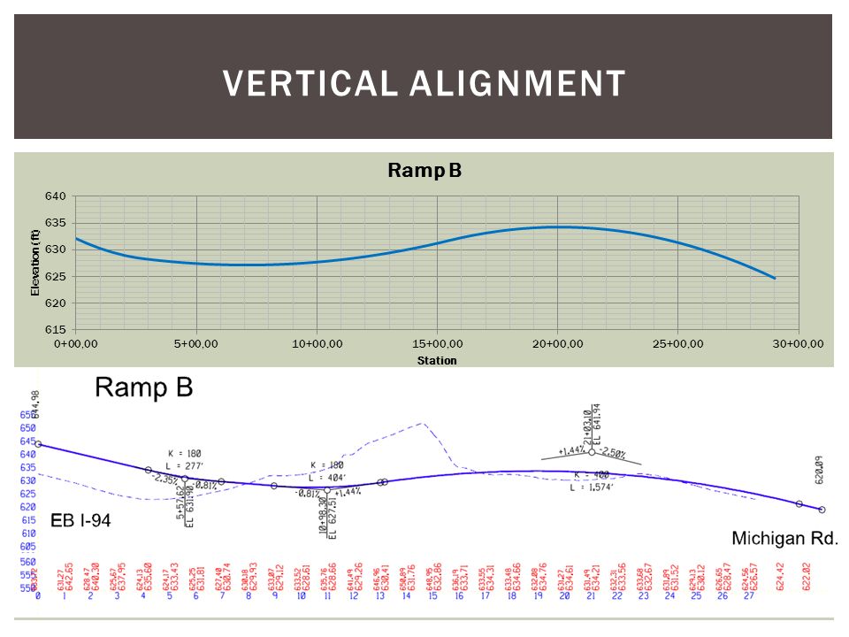
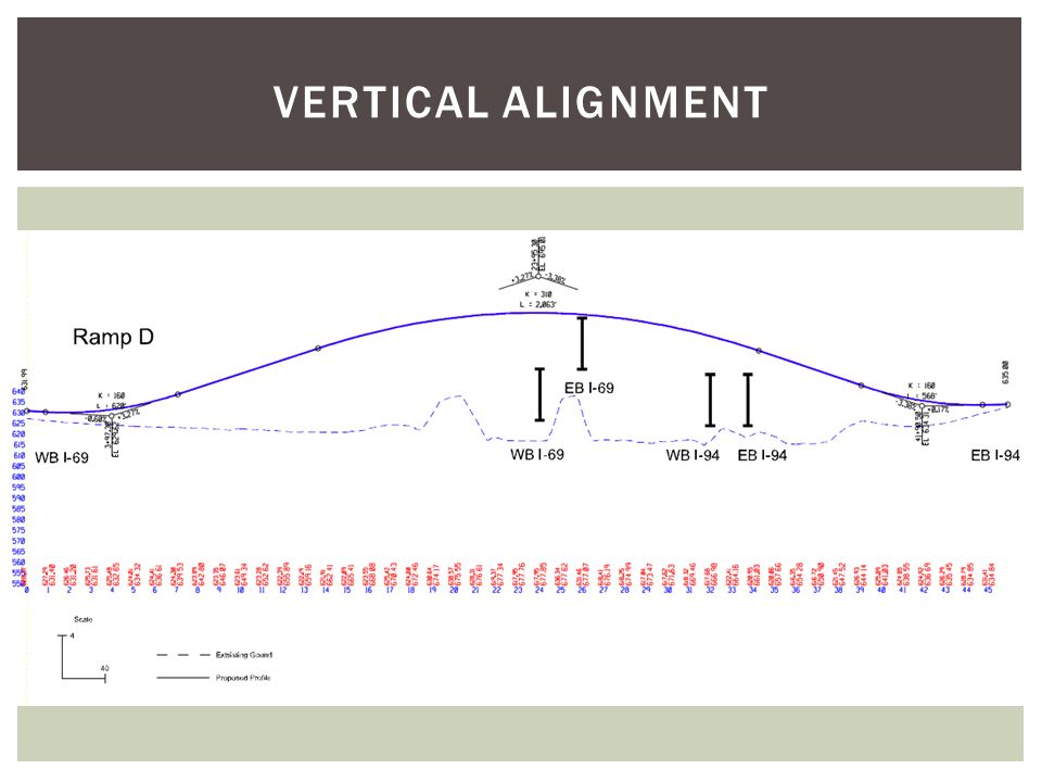
VERTICAL ALIGNMENT (MDOT, 2012)
")
23
VERTICAL ALIGNMENT K Values for Crest CurvesK Values for Sag Curves Design Speed (mph)K K 153 10 207 17 25122526 30193037 35293549 40444064 45614579 50845096 5511455115 6015160136 6519365157 7024770181 7531275206 8038480231 (AASHTO, 2004)
K K (AASHTO, 2004)")
24
Constraints: Match existing elevations and grades at tie in points I-94, I-69, Michigan Road 16’3” clearance for underpassing roads assume conservative 84” bridge thickness Target elevations for 100 year storm MDOT vertical grade restrictions Ramps: -5% to 5% Mainlines: -3% to 3% VERTICAL ALIGNMENT

27
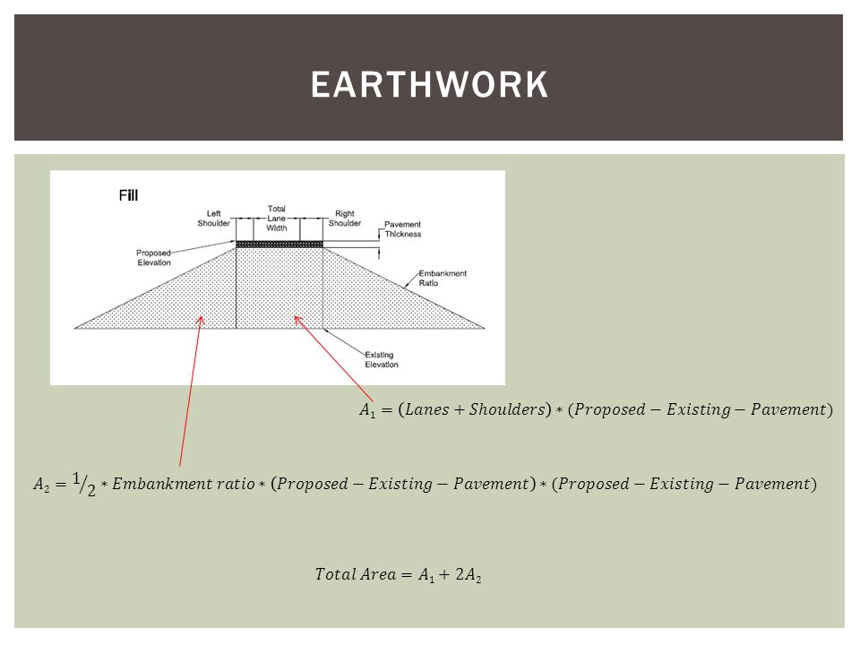
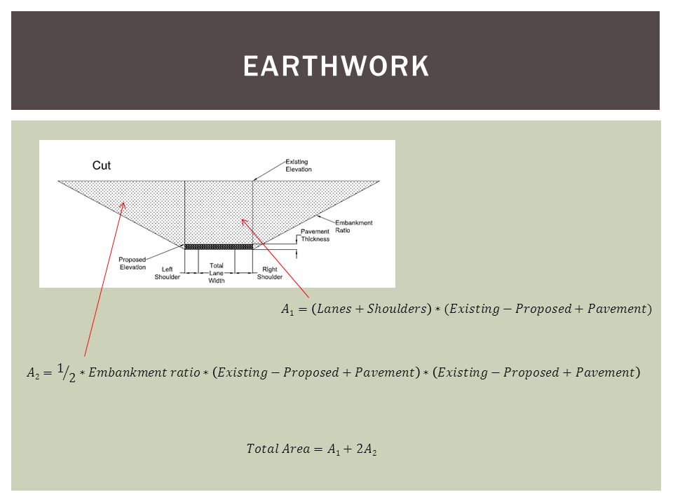
Rigid pavements for entire interchange. Long service lives Less expensive to maintain than flexible pavements Jointed Plain Concrete Pavement (JPCP) Contraction Joints Tie bars and dowel bars Base Course Provides additional load distribution, contributes to drainage Open-Graded Drainage Course material Assumptions for the purpose of earthwork computation 12 inch- Surface Course 16 inch- Base Course PAVEMENT ASSUMPTIONS
 Contraction Joints Tie bars and dowel bars Base Course Provides additional load distribution, contributes to drainage Open-Graded Drainage Course material Assumptions for the purpose of earthwork computation 12 inch- Surface Course 16 inch- Base Course PAVEMENT ASSUMPTIONS.")
28
Average end area method Every station (100 feet intervals) Necessary variables: Proposed elevation Existing elevation Embankment ratios (2:1 for ramp D and eastbound I-69, 4:1 for all other roadways) Pavement thickness (28 inches) Elevations obtained from Microstation function. EARTHWORK

31
Multiply area by station increment (100 feet) and divide by 27 to convert to cubic yards. Earthwork was excluded where bridges exist. Summary: EARTHWORK EARTHWORK (cyd) ROADWAYCUTFILL WB9410,0813 EB9422,700- WB69134,825444 EB696,784141,871 RAMPA1,21288,991 RAMPB36,88414,165 RAMPD-297,638 RAMPF2,6313,926 CUTFILL TOTAL215,117547,038 TOTAL FILL NEEDED331,922
 ROADWAYCUTFILL WB9410,0813 EB9422,700- WB69134, EB696,784141,871 RAMPA1,21288,991 RAMPB36,88414,165 RAMPD-297,638 RAMPF2,6313,926 CUTFILL TOTAL215,117547,038 TOTAL FILL NEEDED331,922.")
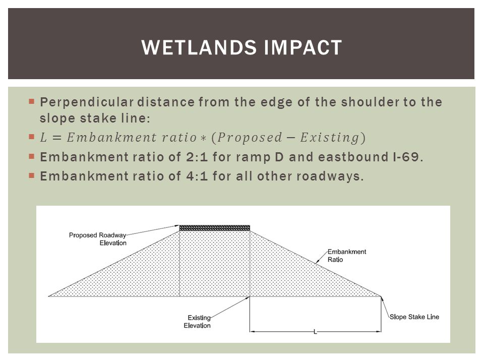
32
Slope stake lines: where embankments meet existing ground profile. Everything within slope stake lines is part of the proposed footprint. Wetlands within slope stake lines will be disturbed. Must replace two acres for every acre disturbed (MDEQ requirement). WETLANDS IMPACT
. WETLANDS IMPACT.")
34
Equation used at every station (100 feet). All points connected to generate slope stake lines. WETLANDS IMPACT

35
Wetlands within footprint: 7.7 acres. Restore 15.4 acres. Within interchange or use wetlands bank. WETLANDS IMPACT

36
COST ESTIMATE

37
Horizontal Alignment: Designed three alternatives Selected alternative 2 Superelevation Transitions Vertical Alignment: Match existing, provide necessary underclearance, hit storm water target points Earthwork: 215,117 cyd of cut, 547,038 cyd of fill Wetlands: Restore 15.4 acres Cost Estimate: $31,768,277 SUMMARY

38
ARE THERE ANY QUESTIONS?

Similar presentations


>")


 Highway Design Procedures/Route Geometric Design/Horizontal Alignment/Circular Curves Lecture.>")


>")


 Sidewalk Feasibility Study Town of Pierson, Florida.>")
