Download presentation
Presentation is loading. Please wait.

1
1 Chapter 1 Basic Structures Of Computers

2
Computer : Introduction A computer is an electronic machine,devised for performing calculations and controlling operations that can be expressed either in logical or numerical terms. Characteristics: Speed Accuracy Diligence Reliability Versatility Resource sharing

3
Computer Architecture Definition It refers to those attributes of a system visible to a programmer (or) It refers to those attributes that have a direct impact on the logical execution of a program. Attributes : Instruction set, number of bits used for data representation, I/O mechanisms, addressing techniques.Computer Architecture. e.g. Is there a multiply instruction?

4
Computer Organization Definition The internal arrangements of a computer, which includes the design of the processor, memory and input / output circuits. (Or) It refers to the operational units and their interconnections that realize the architectural specification. Attributes : Control signals, interfaces, memory technology. e.g. Is there a hardware multiply unit or is it done by repeated addition?
 It refers to the operational units and their interconnections that realize the architectural specification. Attributes : Control signals, interfaces, memory technology. e.g. Is there a hardware multiply unit or is it done by repeated addition .")
5
Structure & Function Structure is the way in which components relate to each other. Function is the operation of individual components as part of the structure.

6
Function All computer functions are: Data processing Data storage Data movement Control

7
Operations (1) :Data movement
 :Data movement")
8
Operations (2) : Storage
 : Storage")
9
Operation (3) :Processing from/to storage
 :Processing from/to storage")
10
Operation (4) :Processing from storage to I/O
 :Processing from storage to I/O")
11
Structure The Computer CPU –Controls the operation of the computer and performs its data processing functions. Main memory –Stores data I/O –Moves data between the computer and its external environment System interconnection –Provides for communication among CPU, main memory, and I/O

12
Structure - Top Level Computer Main Memory Input Output Systems Interconnection Peripherals Communication lines Central Processing Unit Computer

13
Structure - The CPU Computer Arithmetic and Logic Unit Control Unit Internal CPU Interconnection Registers CPU I/O Memory System Bus CPU

14
Structure - The Control Unit CPU Control Memory Control Unit Registers and Decoders Sequencing Logic Control Unit ALU Registers Internal Bus Control Unit

15
Functional Unit

16
Input Unit Input unit reads the data. It captures information and translates it into a form that can be processed by the central processing unit. It accepts inputs in two ways, either manually or directly. Manually : user enters the data by hand. Directly : information is fed into the computer automatically from a source document. Input devices: Keyboard, mouse, joystick and scanners.

17
Central Processing unit It is referred to as ‘brain’ of the computer system, converts data into meaningful information. It controls all internal and external devices, performs arithmetic and logical operations, and operates only on binary data. It controls the usage of main memory to store data and instructions, and controls the sequence of operations. It consists of three main subsystems: The Arithmetic and Logic Unit(ALU) The Control Unit (CU) and The Registers. These three work together to provide the operational capabilities to the computer.
 The Control Unit (CU) and The Registers. These three work together to provide the operational capabilities to the computer..")
18
Arithmetic and logic unit It contains the electronic circuitry that executes all arithmetic and logical operations on the data available to it. It consists of two units: Arithmetic unit: The arithmetic unit contains the circuitry that is responsible for performing the actual computing and carrying out the arithmetic calculations. It performs at a very high speed. Logic unit: It enables the CPU to perform logical operations based on the instructions provided to it. It make logical comparison between data items. It can test for three conditions :’=‘,’>’ and ‘<‘ condition

19
Control Unit It checks the correctness of sequences of operations. It fetches program instruction from the memory, interprets them, and ensures the correct execution of the program. It also controls the input/output devices and directs the overall functioning of the other units of the computer.

20
Registers A Register is a group of flip-flops with each flip- flop capable of storing one bit of information. Registers are special purpose,high speed temporary memory units. It holds various types of information such as data, instructions, address, and the intermediate results of calculations. It offers the advantages of speed.

21
Memory Unit It refers to the electronic holding place for instructions and data. CPU requires memory to handle the intermediate results and to store the final output. It is classified into two categories: Primary Memory(to handle the data):It stores data and instructions for processing. It is also known as Main Memory. It is temporary and limited in size. It is classified into RAM and ROM Secondary Memory (to store the output):It is used for storing instructions and data.It is also known as auxiliary memory. This memory is least expensive and has much larger storage capacity. It is permanent in nature..
:It stores data and instructions for processing. It is also known as Main Memory. It is temporary and limited in size. It is classified into RAM and ROM Secondary Memory (to store the output):It is used for storing instructions and data.It is also known as auxiliary memory. This memory is least expensive and has much larger storage capacity. It is permanent in nature...")
22
Output unit Computers communicate with users using output devices. It take the machine coded output results from the CPU and convert them into a form that is easily readable by users. It processes data into useful information. Hard copy: The physical form of output. Soft copy: The electronic version of an output. Output devices : Printers, Monitors

23
Basic operational concepts –To Execute a given task as per the appropriate program –Program consists of list of instructions stored in memory –Individual instructions are brought from the memory into the processor, which executes the specified operations. –Data to be used as operands are also stored in the memory. –Example: Add LOCA, R0 –Instruction is fetched from the memory into the processor – the operand at LOCA is fetched and added to the contents of R0 – the resulting sum is stored in register R0.

24
Registers Two registers-MAR (Memory Address Register) and MDR (Memory Data Register) : To handle the data transfer between main memory and processor. MAR-Holds addresses, MDR-Holds data Instruction register (IR) : Hold the Instructions that is currently being executed Program counter (PC): Points to the next instructions that is to be fetched from memory. General-purpose register (R 0 – R n-1 )
 : Hold the Instructions that is currently being executed Program counter (PC): Points to the next instructions that is to be fetched from memory. General-purpose register (R 0 – R n-1 ).")
25
Operational concept

26
Operating Steps Programs reside in the memory through input devices. PC is set to point to the first instruction. The contents of PC are transferred to MAR. A Read signal is sent to the memory. The first instruction is read out and loaded into MDR. The contents of MDR are transferred to IR. Decode and execute the instruction. Increments the contents of PC by 1, so that it points to the next instruction address. If data required for operation is available in register, it performs the operation.

27
Steps contd.. Address of the data MAR MAR Address bus ; select memory location where is issued RD signal Reads data via data bus MDR From MDR data can be directly routed to ALU or it can be placed in register and then operation can be performed Results of the operation can be directed towards output device, memory or register Normal execution preempted (interrupt)
.")
28
Interrupt An interrupt is a request from I/O device for service by processor. Processor provides requested service by executing interrupt service routine (ISR). When ISR completed, processor restored, so that interrupted program may continue.
. When ISR completed, processor restored, so that interrupted program may continue..")
29
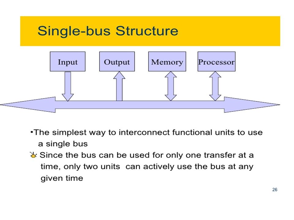
BUS STRUCTURE

30
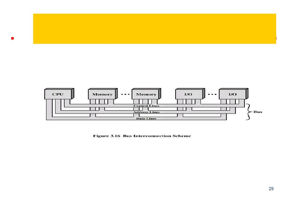
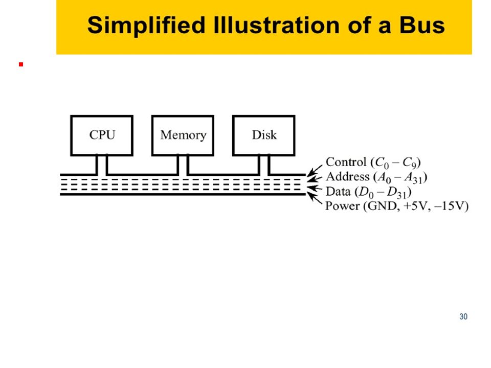
Bus concept Definition: A group of lines that serves as a connecting path for several devices is called a Bus. Bus must have lines for Address Data control

31
Address, data and control bus Data bus: The data lines provide a path for moving data among system modules. These lines collectively called the data bus. It is bidirectional. It consists of 32,64,128 or even more separate lines, the number of lines being referred to as the width of the data bus. The width of the data bus is a key factor in determining overall system performance.

32
Address, data and control bus Address bus: The address lines are used to designate the source and destination of the data on the data bus. It is unidirectional. The width of the address bus determines the maximum possible memory capacity of the system.

33
Address, data and control bus Control bus: The control lines are used to control the access to and the use of data and address lines. It is bidirectional. Control signals transmit both command and and timing information among system modules. Typical control lines include; Memory write, memory read, I/O write,I/O read, Transfer ACK, Bus request, Bus grant, Interrupt request, Interrupt ACK, Clock, Reset

Similar presentations