Download presentation
Presentation is loading. Please wait.

1
Chapter 3 – Diode Circuits – Part 3
Filter Circuits Ripple Factor Capacitor Filter

2
Objective : Convert ac into pure dc voltage

3
Basic dc power supply AC INPUT TRANSFORMER RECTIFIER FILTER
DC OUTPUT AC INPUT

4
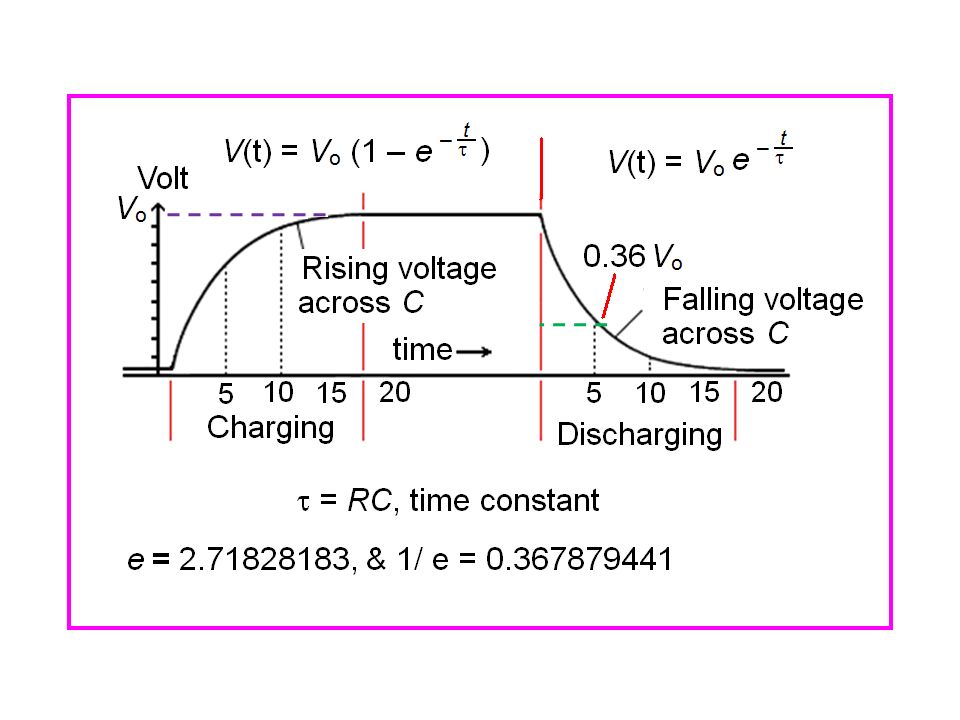
Charging & Discharging of Capacitor

6
Load Resistance/device
Load Resistance/device + C

7
Ripple Voltage The pulsating dc from the rectifier is generally still not suitable to power the actual load circuit. The pulsations typically vary from 0 volts to the peak output voltage of the transformer. The decrease of capacitor voltage depends on RC. The variation in the output dc voltage is called the ripple voltage. Ripple is a small AC signal on the background of a big DC signal.

8
Ripple Factor It is the ratio of the output ac voltage to the output dc voltage across the load resistor RL. Experimental Method to measure the ripple factor: With the ac/dc voltmeter, measure the output ac voltage. Then measure the output dc voltage. The ratio of Vac to Vdc gives the ripple factor. The percentage ripple factor is obtained by multiplying the ripple factor by 100.

9
Mathematical expression of ripple factor:
The ratio of rms value of ac voltage component to dc or average value is known as the ripple factor. RF = VAC / VDC = rms value of ripple peak voltage / VDC = VR/2 / VDC percentage ripple factor = VR/2 / VDC x 100%

10
Example So, if you have a 5 V dc supply that actually varies from to 5.5 V, that's a 1/2 V sinusoid (+/- 1/2 v from nominal), so the ripple factor is 0.5/5 x 100 = 10%. Ripple factor is determined only at the fundamental frequency.
, so the ripple factor is 0.5/5 x 100 = 10%. Ripple factor is determined only at the fundamental frequency.")
11
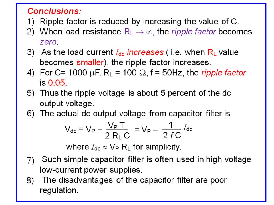
Filter It is desirable to make the ripple factor as small as possible.
Therefore, we insert a circuit after the rectified voltage. This circuit is called a filter. Its job is to reduce the pulses from the rectifier to a much smaller ripple voltage (VR). 4) The capacitor in Filter circuit stores energy during each voltage peak, and then release it to the load when the rectifier output voltage drops.
. 4) The capacitor in Filter circuit stores energy during each voltage peak, and then release it to the load when the rectifier output voltage drops.")
12
Capacitor Filter Bridge Rectifier Filter Circuit

13
Decrease in capacitor voltage, V(t)
")
14
Output voltage of capacitor filter is dc voltage and
small triangular ripple voltage. 2) The capacitor is charged to peak value of the rectified voltage Vp (raising edge of wave). Later discharges through RL during the falling edge of rectified wave. Decrease in capacitor voltage (V(t)) between charging pulses depends upon the relative values of RLC and the period of input voltage T. RLC << T, decrease is large. RLC >> T, decrease is small. 5) Diodes conduct during the portion of the cycle that the capacitor is charging.
 The capacitor is charged to peak value of the rectified. voltage Vp (raising edge of wave). Later discharges through RL during the falling edge. of rectified wave. Decrease in capacitor voltage (V(t)) between. charging pulses depends upon the relative values of RLC and the period of input voltage T. RLC << T, decrease is large. RLC >> T, decrease is small. 5) Diodes conduct during the portion of the cycle that the. capacitor is charging.")
18
Exercise 1: For C= 1000 F, f = 50Hz, find the ripple factor .
RL () Ripple Factor 1 10 100 1000 10000 100000
 Ripple Factor")
Similar presentations


 The 20:1 turns ratio transformer here reduces the rms voltage.>")


. Copyright ©2009 by Pearson Education, Inc. Upper Saddle River, New Jersey 07458 All rights reserved. Electronic.>")


>")

