Download presentation
Presentation is loading. Please wait.

1
Sardar Vallabhbhai Patel Institute Of Technology,Vasad.
Civil Department Building construction By: BURHAN ADENWALA

2
SUBSURFACE INVESTIGATION
The surface and subsurface investigation or site exploration is carried out to collect the information about physical properties and characteristics of the subsoil material as well as the details of other geological features of the site area .

3
Contents Purpose of site exploration Depth of exploration
Methods of site exploration Soil samples and samplers

4
Purpose of Site Exploration
The site exploration or investigation is carried out to collect the complete details of the site for the following purposes : To fix the depth of foundation up to which it must be taken inside the ground. To fix the value of safe bearing capacity of the soil. To predict the likely settlement of the selected foundation and to make the allowance for the same in the design . To know the underground water level. To select an economical and safe type of foundation. To evaluate the earth pressure against the walls ,basements , abutments , etc. and to make the provision against difficulties during construction.

5
Depth Of Exploration The depth of exploration or a trial pit or bore hole will depend upon the characteristics of the soil as well as the type of structure ,its shape , size and loading condition. As a thumb rule , the depth should be one and half times the probable width of the footing or 1.5 m whichever is more. In case of weak soils , however , the pits or the bore holes should be taken to a depth at which the loads can be carried by the soil without undesirable settlement. the number and spacing of the trail pits or bore holes to be adopted for a site will depend upon the area of plot as well as type of structure to be built.

6
Methods of Site Exploration
Trial pits Probing Subsurface soundings Geo physical methods Seismic refraction method Electrical resistivity method Magnetic method Gravitational method 5) Boring Auger boring Auger and shell boring Wash boring Percussion boring Rotary boring
 Boring. Auger boring. Auger and shell boring. Wash boring. Percussion boring. Rotary boring.")
7
Trail Pits The excavation of trial pits is a simple and reliable method. The depth is limited to 4-5m only. The in-situ conditions are examined visually It is easy to obtain disturbed and undisturbed samples Block samples can be cut by hand tools and tube samples can be taken from the bottom of the pit. Walls of the test pit indicate four layers (1) Clayey silt (2) Sandy silt (3) Clean sand (4) Sandy gravel
 Clayey silt (2) Sandy silt (3) Clean sand (4) Sandy gravel.")
8
Trial Pit

9
Probing This method is suitable for soft soils such as clay , gravel and sand. In this method , a steel bar of 25 to 40mm diameter having a pointed end is driven in the ground until a hard strata is met . The bar is allowed to fall vertically under its own weight or it is driven by drop hammer . The bar is drawn out at some interval , so that the rough idea of the nature of strata is obtained from the soil sticking to the sides of the bar. The experienced persons can be engaged in the execution of the driving operation . Fig. shows various types of probing stones:

11
Subsurface Soundings This method consists of measuring the variation in the resistance offered by the soil with the depth by means of a tool known as penetrometer. The penetrometer may consist of a 50 mm diameter mild steel cone fitted loosely to a steel rod or it may be a tool known as standard split spoon sampler. The resistance offered by the soil to penetration is co- related with the engineering properties of soil , such as – density , consistency , permeability and bearing capacity.

12
Boring The various boring methods adopted for soil exploration are as follows : Auger boring Auger and shell boring Wash boring Percussion boring Rotary boring

13
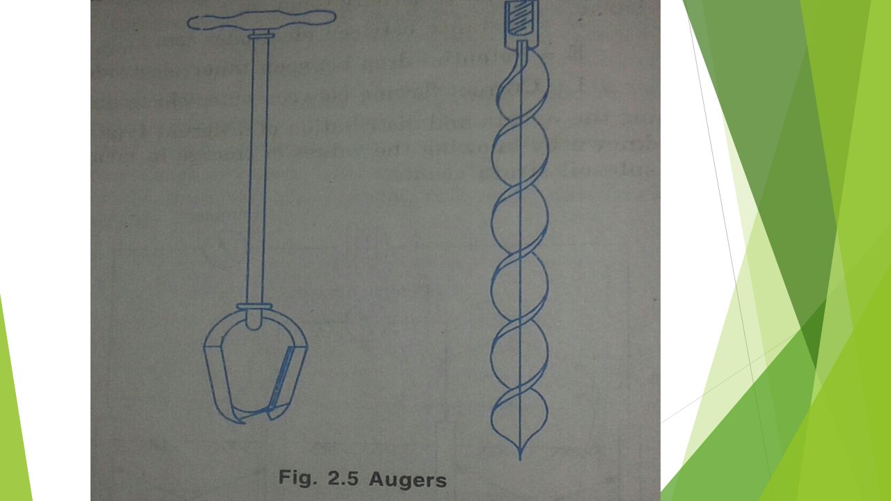
Auger Boring This type of augers are commonly used for clayey or sandy soils or soft soils . It can be operated manually or mechanically . The hand operated augers are used up to 6 m depth and the mechanically operated augers are used for greater depth up to 15 m . The auger is vertically driven into the ground by rotating its handle and is pressed down during the process of rotation . At every 30 cm depth of penetration , the auger is drawn out and the samples of soils are collected separately for testing .

15
Auger and Shell Boring In this method ,different types of tools are used for boring. In case of soft clay , cylindrical auger having 75 to 200 mm diameter hollow tube with a cutting edge at its bottom is used . In case of hard clay , the shells with cutting edge or teeth at its lower end are used ; while in case of sandy soil or sand , the pumps are used for boring . The hand operated rigs are used 25 m depth up to 200 mm diameter and the mechanical rigs are used for 50m depth. The samples of soil are collected at regular interval for testing .

16
Wash Boring A casing is driven with a drop hammer. A hollow drill rod with chopping bit is inserted inside the casing. Soil is loosened and removed from the borehole using water or a drilling mud jetted under pressure. The water is jetted in the hole through the bottom of a wash pipe and leaves the hole along with the loose soil, from the annual space between the hole and wash pipe. The water reaches the ground level where the soil in suspension is allowed to settle and mud is re- circulated.

17
Schematic for wash boring

18
Percussion Boring This method is used for rocks and soils having boulders ; which are broken up by repeated blows from a bit or chisel . Thus , the pulverised material is converted into slurry by pouring water in the bore and this slurry is bailed out at regular interval and dried for testing.

19
Rotary Boring The rig consists of a derrick, power unit, winch, pump and a drill head to apply high-speed rotary drive and downward thrust to the drilling rods. Primarily intended for investigation in rock, but also used in soils. The drilling tool, (cutting bit or a coring bit) is attached to the lower end of hollow drilling rods The coring bit is fixed to the lower end of a core Water or drilling fluid is pumped down the hollow rods and passes under pressure through narrow holes in the bit or barrel The drilling fluid cools and lubricates the drilling tool and carries the loose debris to the surface between the rods and the side of the hole.
 is attached to the lower end of hollow drilling rods. The coring bit is fixed to the lower end of a core. Water or drilling fluid is pumped down the hollow rods and passes under pressure through narrow holes in the bit or barrel. The drilling fluid cools and lubricates the drilling tool and carries the loose debris to the surface between the rods and the side of the hole.")
20
The fluid (bentonite slurry) also provides some support to the sides of the hole if no casing is used There are two forms of rotary drilling, open-hole drilling and core drilling. Open- hole drilling, which is generally used in soils and weak rock, just for advancing the hole The drilling rods can then be removed to allow tube samples to be taken or in-situ tests to be carried out. In core drilling, which is used in rocks and hard clays, the diamond or tungsten carbide bit cuts an annular hole in the material and an intact core enters the barrel, to be removed as a sample. Typical core diameters are 41, 54 and 76mm, but can range up to 165 mm.

21
Soil Samples and Samplers
Disturbed samples Undisturbed samples Soil samplers Open drive sampler Stationary piston sampler Rotary sampler

22
Soil Samples Disturbed samples :
A disturbed sample is a sample in which the natural structure of soil gets partly or fully modified and destroyed . However , by taking proper precautions , the natural water content in soil sample can be preserved . This type of soil sample should maintain the original proportion of the various particles . Undisturbed samples : An undisturbed sample is a sample which the natural structure and properties remain preserved . The sample disturbance depends on the design of samplers and the method of sampling . The sampling tube when forced into the ground should cause as little remoulding and disturbance as possible .

23
Types of Samplers The samplers are classified as – Thick wall samplers
Thin wall samplers Depending upon the area ratio. The thick wall samplers are those having the area greater than 10% . Depending on the mode on operation , the samplers are classified as – Open drive sampler Stationary piston sampler Rotary sampler

24
Open Drive Sampler The open drive sampler is a tube open at its lower end .the sampler head is provided with vents (valves) to permit water and air to escape during driving . The check valve helps to retain sample , when the sampler is lifted up . The tube may be seamless or it may split in two parts , which may be known as split spoon sampler .
 to permit water and air to escape during driving . The check valve helps to retain sample , when the sampler is lifted up . The tube may be seamless or it may split in two parts , which may be known as split spoon sampler .")
25
Stationary Piston Sampler
It consists of a sample cylinder and the piston system . During lowering of the sampler through hole , the lower end of the sampler is kept closed with the piston. When the desired sampling elevation is reached , the piston rod is clamped , thereby keeping the piston stationary and the sampler tube in advanced down into the soil . The sampler is then lifted up with piston rod clamped in position . This type of sampler is more suitable for sampling soft soils ,saturated sands .

26
Rotary Sampler The rotary sampler are the core barrel type having an outer tube provided with a cutting teeth and a removable thin wall liner inside . It is used for firm to hard cohesive soils and cemented soils .

27
THANK YOU

Similar presentations


>")


 to the ground within allowable settlement criteria.>")


