Download presentation
Presentation is loading. Please wait.

1
LFB, LLRF, TFB Alessandro Drago Annecy, 16-19 March 2010

2
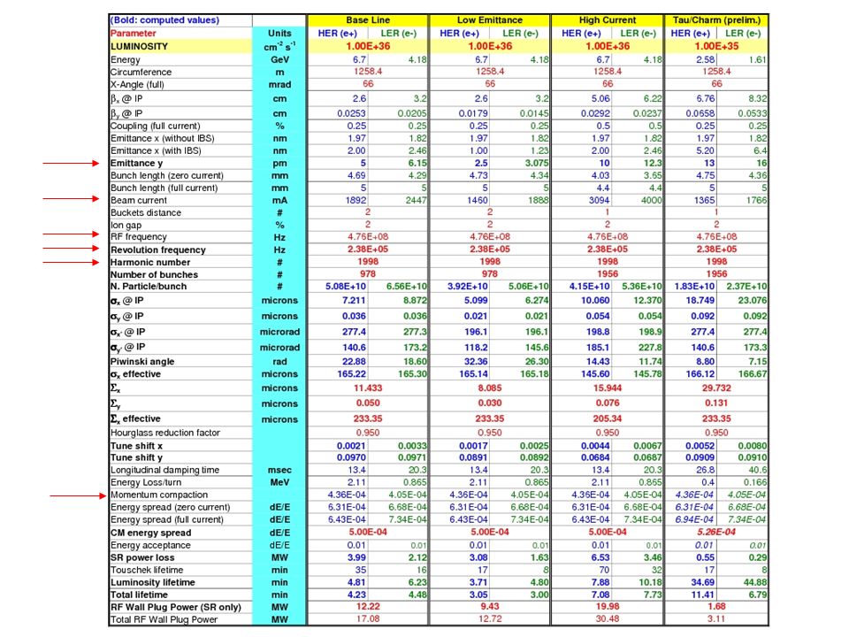
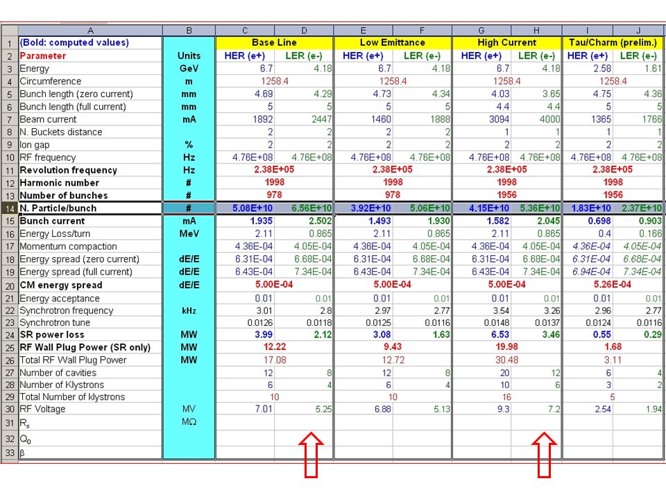
Introduction Activities on different design aspects are in progress with analysis of the last parameters data set LFB: Longitudinal beam / RF / b-b-b fb preliminary simulations Low Level RF spec’s discussion Transverse feedback upgrades Conclusions

5
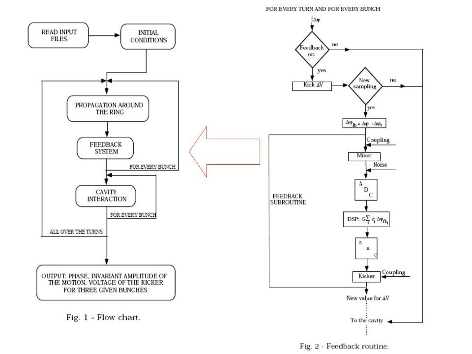
Simul2 longitudinal simulator Developed by Mauro Migliorati in 1992 Written in FORTRAN Longitudinal beam + RF + LFB behavior code Modern data I/O interface re-written in Matlab including (“embedded”) the previous FORTRAN program Data base input by editor: this, for some data, is not the fast way to insert new inputs With large amount of beam current and bunches the every simulation run can take more than 40 minutes - so to test many different data set can be very time consuming
 the previous FORTRAN program Data base input by editor: this, for some data, is not the fast way to insert new inputs With large amount of beam current and bunches the every simulation run can take more than 40 minutes - so to test many different data set can be very time consuming")
7
11 RF modes in data base

8
LER – baseline parameters - full current (2.447A) – b.space 2 – rad.loss 2MeV/turn – no injection kick – no feedbacks the beam is lost ph*.dat contains the phase of a bunch as a function of the number of turns, phsp*.dat contains the longitudinal invariant of the motion. In order to see the exponential growth of the instability it is easier to work with the invariant since the phase is subject to the synchrotron oscillations. 30k turns

9
LER – 70% current – b.space 2 – rad.loss 2 MeV/turn – no inj.kick – no LFB

10
LER – 70% current – b.space 2–rad.loss 0.8 MeV/turn – no inj.kick – no LFB Decreasing the radiation loss/turn LFB is clearly needed

11
FIR filter (LER) with phase response at exactly -90 degrees Synchrotron frequency 2.8kHz Down sampling factor =14 Taps = 6 coefficient = 0 0.85927 0.87907 0.040054 -0.83809 -0.89746 deltaT = 5.8765e-5 sec
 with phase response at exactly -90 degrees Synchrotron frequency 2.8kHz Down sampling factor =14 Taps = 6 coefficient = deltaT = e-5 sec")
12
Changing synchrotron phase response to +45 degree FIR filter coefficient: 0.7071 0.9693 0.2845 -0.6782 -0.9784 -0.3227

13
-90+45 degree: good damping ! ~10E-3

14
Exactly -90 degree: better damping (500w) ! <10E-3
 ! <10E-3")
15
Full current, fb on: 500W

16
Simulation data: full current (2.447A), 978 bunches, lfb on, power amplifiers=1kW multibunch longitudinal motion damped FIR filter implemented
, 978 bunches, lfb on, power amplifiers=1kW multibunch longitudinal motion damped FIR filter implemented")
17
Full current, fb on, 5kW, much better damping time

18
High current case (4A), but spaced by 2, lfb on, 1kW power is not more sufficient and the beam is lost
, but spaced by 2, lfb on, 1kW power is not more sufficient and the beam is lost")
19
High current case (4A), sp.by 2, lfb on, also 2kW power is not sufficient and the beam is lost again
, sp.by 2, lfb on, also 2kW power is not sufficient and the beam is lost again")
20
High current case (4A), sp.by 2, lfb on, increasing the power, 2.5kW is now sufficient to control the beam longitudinal dynamics
, sp.by 2, lfb on, increasing the power, 2.5kW is now sufficient to control the beam longitudinal dynamics")
21
High current case (4A), sp.by 2, lfb on, with 5kW the power controls more efficiently the beam longitudinal dynamics
, sp.by 2, lfb on, with 5kW the power controls more efficiently the beam longitudinal dynamics")
22
LLRF - Low Level RF System description (from CDR2 by Sacha Novokhatski) A low-level RF system provides control and feedback for stable multi- bunch high current operation. There are several feedback loops. BLOCK DIAGRAM OF LLRF CIRCUITS

23
LLRF System description (from CDR2 by S.N.) The direct loop is required for lowering the cavity impedance to reduce multi-bunch oscillations of the beam. Functionally the direct loop keeps the gap voltage constant as set by a DAC reference over an 800 kHz bandwidth. The loop compares the combined baseband field signals of a station's cavities to the reference generated by the gap module. The resultant error signal is up-converted to RF and drives the klystron. The direct loop contains a PID controller with an integral compensation for smoothing out the ripple caused by the klystron high voltage power supply and lead compensation that increases the bandwidth and gain of the loop. The direct feedback loop options control the optional functions of the direct loop: frequency offset tracking, integral compensation and lead compensation. The frequency offset tracking loop takes out the phase shift caused by detuning of the cavities during heavy beam loading. It is used as a diagnostic for adjusting the waveguide network. The comb loop provides additional impedance reduction for the cavities at specific synchrotron frequency sidebands around the revolution harmonics of the beam. It operates over a bandwidth of 2 MHz and includes a 1 turn delay. The tuner loop tunes and maintains each cavity at resonance. It corrects for thermal frequency variations and compensates cavity beam loading by keeping the phase relationship between forward power and cavity field, as seen by the cavity probe, constant. The relevant phases are measured by digital IQ detectors and the loop is completed in software controlling the tuner position via a stepping motor. The HVPS loop adjusts the voltage to the klystron to provide sufficient output power to operate the station under whatever gap voltage or beam loading is requested. Functionally the loop keeps the klystron operating at about 10% below saturated output power. The loop measures the drive power at the input to the klystron and compares it to the ON CW drive power set-point. Based on the error the set-point for the high voltage power supply is adjusted up for excessive drive and down for insufficient drive. This is a slow loop with about a 1 Hz bandwidth. The DAC loop is a slow (0.1 Hz bandwidth) loop in software which functionally keeps the measured gap voltage of the station equal to it's requested "Station Gap Voltage" by adjusting the DAC in the gap voltage feed-forward module. The ripple loop is intended to remove amplitude and phase ripple in the klystron output power but at the time it is only utilized to keep the low bandwidth phase across the klystron and drive amplifier constant as the klystron voltage is varied. The gap feed forward loop is required to tell the direct loop to ignore the effects of the ion-clearing gap in the beam bunch train. Functionally the loop learns about the variation in the klystron drive caused by the beam gap and adds an equal variation in the reference signal so that the error signal driving the klystron stays unchanged. This loop adapts fully in about 1000 beam revolutions. The longitudinal feedback woofer is the third cavity impedance reduction loop along with the direct loop and the comb loop. It derives it's information from the lowest beam oscillation modes detected by the longitudinal bunch-by- bunch feedback system and uses one RF station in each ring as a powerful longitudinal kicker.
 loop in software which functionally keeps the measured gap voltage of the station equal to it s requested Station Gap Voltage by adjusting the DAC in the gap voltage feed-forward module. The ripple loop is intended to remove amplitude and phase ripple in the klystron output power but at the time it is only utilized to keep the low bandwidth phase across the klystron and drive amplifier constant as the klystron voltage is varied. The gap feed forward loop is required to tell the direct loop to ignore the effects of the ion-clearing gap in the beam bunch train. Functionally the loop learns about the variation in the klystron drive caused by the beam gap and adds an equal variation in the reference signal so that the error signal driving the klystron stays unchanged. This loop adapts fully in about 1000 beam revolutions. The longitudinal feedback woofer is the third cavity impedance reduction loop along with the direct loop and the comb loop. It derives it s information from the lowest beam oscillation modes detected by the longitudinal bunch-by- bunch feedback system and uses one RF station in each ring as a powerful longitudinal kicker..")
24
SuperB LLRF design project Olivier (olivier.bourrion@lpsc.in2p3.fr)olivier.bourrion@lpsc.in2p3.fr and Christophe (vescovi@lpsc.in2p3.fr)vescovi@lpsc.in2p3.fr are going to study a preliminary LLRF design proposal. A discussion of the specifications is started.

25
SuperB bunch-by-bunch feedbacks bunch 2.1 ns Operator interface realtime and offline analysis programs DPU 16bit DAC FPGA 12bit ADC DPU 16bit DAC FPGA 12bit ADC 250W/500W x x 6*RF LP RF (476MHz) Inj.Trigger User trigger LAN Comb gen. a*RF 0 180 250W AM Phase detector x 3*RF LPAmplitude detector 31.5cm longitudinal transverse

26
TFB front end tests on DAFNE In collaboration with KEK (M.Tobiyama) And, partially, with SLAC (J.Fox)
 And, partially, with SLAC (J.Fox)")
27
TFB front end components In collaboration with KEK (M.Tobiyama) Qpsk generator circuit designed for SuperKEKB
 Qpsk generator circuit designed for SuperKEKB")
28
Two iGp feedback systems (but without source code!) with 12-bit ADC and 16 bit DAC have been ordered to Dimtel inc., and will be tested in the next DAFNE run Two new LFB front end Are also been bought to be tested in the next DAFNE run
 with 12-bit ADC and 16 bit DAC have been ordered to Dimtel inc., and will be tested in the next DAFNE run Two new LFB front end Are also been bought to be tested in the next DAFNE run")
29
Conclusions the new beam parameters have been inserted in the Simul2 longitudinal simulator data base The simulator can accept the new data set without changes to the code – Preliminary runs have be done in the last week Having radiation loss as in the table, a bunch-by-bunch longitudinal feedback is necessary to run at full beam current (2.447A) or more The LFB FIR filter has been designed and damps well The longitudinal power shall be at least 1kW (=4x250 W amplifiers) The option high current (4A) asks for more power, of the order of 2.5kW – this corresponds to ten 250W amplifiers A discussion on the LLRF spec’s is started in collaboration with the Grenoble team For the vertical FB, a first upgrade of the iGp system with 12-bit ADC and full compatibility with the old software will be tested in the next DAFNE run Other design and test activities are in progress for the LFB and the TFB with the goal to be tested in the next DAFNE runs starting from May of this year.
 or more The LFB FIR filter has been designed and damps well The longitudinal power shall be at least 1kW (=4x250 W amplifiers) The option high current (4A) asks for more power, of the order of 2.5kW – this corresponds to ten 250W amplifiers A discussion on the LLRF spec’s is started in collaboration with the Grenoble team For the vertical FB, a first upgrade of the iGp system with 12-bit ADC and full compatibility with the old software will be tested in the next DAFNE run Other design and test activities are in progress for the LFB and the TFB with the goal to be tested in the next DAFNE runs starting from May of this year.")
Similar presentations

 and L. F. Wang (SLAC) ECLOUD07, 12th Apr. 2007, Daegu, Korea 1. Introduction 2. Ion trapping 3. Fast ion instability.>")
 and Anil.>")


, John Byrd (LBNL) General Issues RF phase and amplitude noise –filtered by cavity and translate into timing.>")


 LCWS2013 at Tokyo Uni., 11-15 Nov. 2013 KEK, Junji.>")


>")
