Download presentation
Presentation is loading. Please wait.

1
PRESENTED BY : SHOUBHIK MUKHERJEE EN(final year)
")
3
GORAKHPUR is the headquarters of NORTH EASTERN RAILWAYS. The mechanical workshop,NER GORAKHPUR,was established in 1903. Steam engines were maintained here for a long time,but now diesel engines,coaches,and wagons are the main subjects of maintenance here. The workshop became a part of the East Indian Railways & during the regrouping of the railways,after independence,GORAKHPUR WORKSHOP emerged as the major workshop on NORTH EASTERN RAILWAYS. The GORAKHPUR WORKSHOP is more than 110 years old & is one of the rare workshops.

4
An alternator is an electromechanical device that converts mechanical energy to electrical energy in the form of alternating current. A voltage regulator is an electrical regulator designed to automatically maintain a constant voltage level.

5
1.)SYSTEM DESCRIPTION Bosch alternators are conventional 3-phase,self-rectifying type alternators.Bosch 110 amp alternators use 14 diodes. 2.)WIRING CONTINUITY TEST Connect a voltmeter between alternator Red battery terminal wire and check ground voltmeter reading. 3.)ALTERNATOR EXCITER CIRCUIT TEST 3.1. CURRENT CHECKING Check that battery voltage is a minimum of 12 volts.If not,charge as needed & then disconnect the wire from alternator terminal & connect Multimeter.
WIRING CONTINUITY TEST Connect a voltmeter between alternator Red battery terminal wire and check ground voltmeter reading. 3.)ALTERNATOR EXCITER CIRCUIT TEST 3.1. CURRENT CHECKING Check that battery voltage is a minimum of 12 volts.If not,charge as needed & then disconnect the wire from alternator terminal & connect Multimeter..")
6
3.2. RESISTANCE CHECKING Disconnect negative battery cable of the alternator. Connect Multimeter between cable and positive terminal of the battery. 3.3. OUTPUT CHECK Ensure connections at battery,alternator & starter are clean & tight.Also ensure that alternators are properly grounded. Connect Ammeter/Voltmeter or equivalent,following manufacturer’s instructions. Repeat test at 2000RPM & alternator output should be 90- 110amps or within 10% of manufacturer’s specification.

8
4.)DIODE ASSEMBLY BENCH TESTING Place ohmmeter on scale & connect ohmmeter leads across positive terminal & each of the 3 stator terminals. Connect ohmmeter leads across negative plate and each of the 3 stator terminals. 5.)STATOR BENCH TESTING Place ohmmeter on lowest scale & connect ohmmeter across stator leads. Place ohmmeter on scale & connect ohmmeter between stator core & stator lead. 6.)ROTOR BENCH TESTING Place ohmmeter on lowest scale & connect ohmmeter across slip rings.
STATOR BENCH TESTING Place ohmmeter on lowest scale & connect ohmmeter across stator leads. Place ohmmeter on scale & connect ohmmeter between stator core & stator lead. 6.)ROTOR BENCH TESTING Place ohmmeter on lowest scale & connect ohmmeter across slip rings..")
9
If resistance is too low,rotor has short circuit & must be replaced. Place ohmmeter on scale & connect ohmmeter between either slip ring rotor core. Clean slip rings using fine sandpaper. If slip rings are beyond repair,remove them or replace them. 7.)BEARINGS BENCH TESTING Always replace bearings in case of overhauling alternator. If replacement front bearing is sealed on one side only,open side must face rotor. If replacement rear bearing is sealed on one side only,open side must face away from rotor. 8.)BRUSHES BENCH TESTING Ensure brushes are longer than 5.56mm.
BEARINGS BENCH TESTING Always replace bearings in case of overhauling alternator. If replacement front bearing is sealed on one side only,open side must face rotor. If replacement rear bearing is sealed on one side only,open side must face away from rotor. 8.)BRUSHES BENCH TESTING Ensure brushes are longer than 5.56mm..")
11
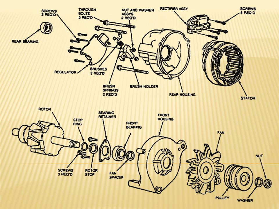
1.)INSTALLATION FOR THE NEW GEN HEAD ASSEMBLY A REMOVAL OF THE OLD STYLE STEP 1-Remove the end cover off the gen head using a wrench. STEP 2-Once the end cover is removed,disconnect the wires to the capacitor and the stator. STEP 3-Remove the nuts underneath the support bar on the frame. STEP 4-Remove the stator. STEP 5-Remove the rotor bolt. STEP 6-Remove the rotor.

12
B INSTALLATION OF THE NEW STYLE STEP 1-Install rotor. STEP 2-Install rotor through bolt & nut. STEP 3-Install stator. STEP 4-Install bearing support. STEP 5-Remove the old one & install the new one. STEP 6-Remove the old gen head & install the new gen head. STEP 7-Reconnect the wires to the capacitor. STEP 8-Connect the remaining wires by colour. 2.)TO RE-EXCITE GENERATOR If no output,reverse the engine to full for no more than 3 seconds.This will re-excite the gen head. If still no output,shut engine off.
TO RE-EXCITE GENERATOR If no output,reverse the engine to full for no more than 3 seconds.This will re-excite the gen head. If still no output,shut engine off..")
13
3.)TO CHECK CAPACITOR Remove the end cover screws and end cover from gen head. Remove capacitor leads. Open circuit from beginning indicates bad capacitor. 4.)TO CHECK STATOR If the capacitor checks okay,check for open circuits in stator If open circuits are not found & there is still a problem,check for circuits grounded in stator. 5.)TO CHECK IDLE CONTROL SWITCH Place idle control switch in the OFF position. Remove the two screws from the front of idle control switch. Disconnect wire harness from idle control switch.
TO CHECK STATOR If the capacitor checks okay,check for open circuits in stator If open circuits are not found & there is still a problem,check for circuits grounded in stator. 5.)TO CHECK IDLE CONTROL SWITCH Place idle control switch in the OFF position. Remove the two screws from the front of idle control switch. Disconnect wire harness from idle control switch..")
Similar presentations


 Using Multimeters Karl Davies 1 East Kent Radio Society.>")


>")
 K.V.2,FCI GORAKHPUR.>")

 by Herb Spenner.>")


