Download presentation
Presentation is loading. Please wait.

1
, 03.12.08 Summary of Working Group 1 Linear Colliders and Light Sources C. Christou, M. Dehler

2
, 03.12.08 Goals: Review state of the art in linear colliders and light sources Applicability of X band structures as basic building blocks Demands for X band power sources and accelerating structures

3
, 03.12.08 One dedicated session heavily concentrated on light sources (3 presentations), one lost sheep from WG2 Global joint session, our special focus X band sources, availability and cost Joint with WG4: Standard components
, one lost sheep from WG2 Global joint session, our special focus X band sources, availability and cost Joint with WG4: Standard components")
4
RF Systems Linac: 3GHz 2 x 5.2m Cu DESY structures 2 x 35MW klystrons bunchers Booster: 500MHz 1 x 5 cell Cu PETRA cavity 1 x 60kW IOT Storage ring: 500MHz 3 x 1 cell Nb Cornell cavities 3 x 300kW IOT complex Cavities from Accel. Amplifiers from Thales

5
Beamtime Statistics (to end Sep.) 2008: 3177h delivered with 95.0% uptime, MTBF = 14.6 h 2007: 3120h delivered with 92.4% uptime, MTBF = 10.0 h
 2008: 3177h delivered with 95.0% uptime, MTBF = 14.6 h 2007: 3120h delivered with 92.4% uptime, MTBF = 10.0 h")
6
The UK’s New Light Source Project Project to consider the scientific case and develop a conceptual design for a possible next generation light source based on a combination of advanced conventional laser and free-electron laser sources. STFC Daresbury and Rutherford Laboratories Accelerator Science and Technology Centre (ASTeC) Central Laser Facility (CLF) Diamond Light Source John Adams and Cockcroft accelerator institutes Various Universities www.newlightsource.org NLS Progress Official Launch, April 11th 2008 Science Workshops, May 13th – June 19th Draft Science Case published, Sep. 11th Science Case approved by the Physical And Life Science committee of the STFC, Oct. 17th approval to proceed to the design stage
 Central Laser Facility (CLF) Diamond Light Source John Adams and Cockcroft accelerator institutes Various Universities NLS Progress Official Launch, April 11th 2008 Science Workshops, May 13th – June 19th Draft Science Case published, Sep. 11th Science Case approved by the Physical And Life Science committee of the STFC, Oct. 17th approval to proceed to the design stage.")
7
NLS: normal conducting option DesignDESY structure SLAC structure Length5.2 m3.0 m Shunt impedance 51.5 MΩ/m52 MΩ/m Mode2π/3 Q1400012500 Filling time740 ns690 ns Number of cells 15689 DesignNLC/LCLS structure Length0.6 m Shunt impedance 30 MΩ Mode5π/6 S-band for accelerationX-band for phase space linearisation at input to BC1

8
NLS: superconducting option Possible SRF Linac Parameters for NLS

9
Upgrade Paths Higher photon energies, ≥ 1.5 keV – additional linac Increased rep. rate, ≥ 10 kHz – VHF/SC gun Longitudinal coherence to ≥ 1 keV – improved seeding sources Shorter pulses, ≤ 1 fs – slicing/single-spike Additional FELs/experimental stations Latest News NLS Project Governing Body agreed on Nov. 19th to proceed with the cw superconducting option. Studies will now concentrate on both the straight and recirculating SC linac options, with 1 keV baseline photon energy.

10
4 th Generation Machines Worldwide Blue – single-stage Red – multi-stage (inc. harmonic correction) Yellow – ERL (various methods) Bold – they have measured that bunch length NLS SC Design NLS NC Design Users want 1kHz rep. rate, 20fs pulses, 3 GeV ideally Our initial interpretation, a ~1 GeV SC linac, upgradable to 3 GeV Other approach, a 3 GeV NC linac (R. Bartolini) Recirculating option being developed
 Yellow – ERL (various methods) Bold – they have measured that bunch length NLS SC Design NLS NC Design Users want 1kHz rep. rate, 20fs pulses, 3 GeV ideally Our initial interpretation, a ~1 GeV SC linac, upgradable to 3 GeV Other approach, a 3 GeV NC linac (R. Bartolini) Recirculating option being developed.")
11
Similar Schemes to a SC NLS WiFEL LBNL Both about 2 GeV Both about 600 m (facility)
")
12
An NLS SC Design (Hywel Owen and Peter Williams) 735 MeV chosen as it corresponds to 1 nm, the limit for HHG seeding i.e. this is a possible extraction energy where we want short bunches Compression scheme must be carefully designed – linearisation, cavity wakefield compensation, CSR, LSC 200 pC bunch charge chosen, based injector on XFEL EPAC08: MOPC034, MOPC035 available at www.jacow.orgwww.jacow.org PR-STAB in preparation ParameterValue Bunch Charge200 pC Fundamental RF1.3 GHz Bunch Rate1 kHz to 1 MHz Gradient17 MV/m 3.9 GHz Total Voltage20 MV Transverse Slice Emittance< 2 mm-mrad rms Energy Spread4.1 MeV Bunch Length10 fs

13
Why superconducting in the UK? ‘Mega-facilities’ already under construction – LCLS, XFEL, SCSS, with different pulse patterns, but all ‘low rep. rate’. Provide short wavelength output c. 1 A. Lower-energy ‘low rep. rate’ facilities already operating, under construction or proposed – FLASH, FERMI, MAXLAB etc. Low rep. rate machine (e.g. up to 400 Hz) can use NC cavities, e.g. S-band, C-band, using established technology – therefore cheap, but not competitive User advantages of SC all from higher rep. rate –Bunch properties about the same –Synchronisation might be easier –Experiments faster, or different ones possible Disadvantages: –Greater Capital cost (about 1.7 times cf. NC on NLS) –Cryoplant –Lower gradient than C-band (about the same as S-band) – up to 20 MV/m An X-band solution should compete on: –Higher gradient –Lower cost cf. SC –Rep. rate higher than 1 kHz to compete against S-band –At lower energies, want all X-band to minimise facility length –Wakefields an issues for short bunch production (important)
 can use NC cavities, e.g. S-band, C-band, using established technology – therefore cheap, but not competitive User advantages of SC all from higher rep. rate –Bunch properties about the same –Synchronisation might be easier –Experiments faster, or different ones possible Disadvantages: –Greater Capital cost (about 1.7 times cf. NC on NLS) –Cryoplant –Lower gradient than C-band (about the same as S-band) – up to 20 MV/m An X-band solution should compete on: –Higher gradient –Lower cost cf. SC –Rep. rate higher than 1 kHz to compete against S-band –At lower energies, want all X-band to minimise facility length –Wakefields an issues for short bunch production (important).")
14
FERMI@Elettra Financed by MIURMIUR FVG RegionFVG Region EIBEIB Spreader & FEL Hall Experimental Hall Linac

15
FERMI objectives Beam energy 1.2 GeV (Phase I), 1.5 GeV (Phase II) 10-50 Hz pulse repetition rate, 1 e-bunch/pulse Seeded operation with Harmonic Generation Spectral range: Phase I 100 (80) – 40 (20) nm, single stage Phase II 40 (20) – 10 (5) nm, two stages Short sub-ps pulses 200 fs Flexible polarization, gap tuning, apple type undulators Construction of a single-pass FEL User Facility, in the soft X-ray region, based on the existing Normal Conducting S- band Linac.
, 1.5 GeV (Phase II) Hz pulse repetition rate, 1 e-bunch/pulse Seeded operation with Harmonic Generation Spectral range: Phase I 100 (80) – 40 (20) nm, single stage Phase II 40 (20) – 10 (5) nm, two stages Short sub-ps pulses 200 fs Flexible polarization, gap tuning, apple type undulators Construction of a single-pass FEL User Facility, in the soft X-ray region, based on the existing Normal Conducting S- band Linac.")
16
FERMI machine layout Laser heater E~100 MeV 9 Slac type FW_TW 2/3 (3.0 - 4.5 m) without Sled 7 nose cone BW_TW 3/4 (6.1 m) with Sled X-Band structure E 3 =1200/1500 MeV
 without Sled 7 nose cone BW_TW 3/4 (6.1 m) with Sled X-Band structure E 3 =1200/1500 MeV")
17
First photoelectrons Courtesy of M. Trovo’

25
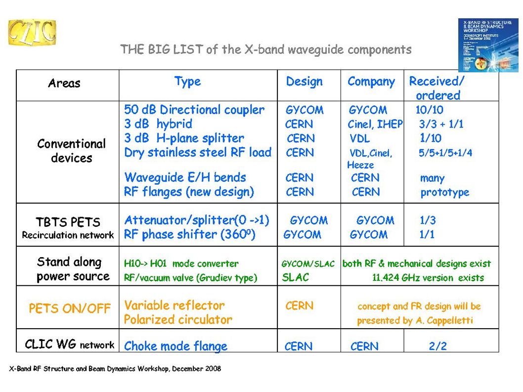
Cost discussion Main cost driver is klystron Usual economies of scale apply –Price starts coming down over 10 units CLIC will require larger number of X-band klystrons for testing, commissioning… Specification still not standardised

Similar presentations


 R. Garoby (for the SPL study group) SPL-based Proton Driver for Facilities SPL-based Proton Driver for Facilities at CERN:>")

 –Linear.>")


>")
 Photoinjector laser system.>")


 Robert Bosch, Kevin Kleman and the WiFEL team Synchrotron Radiation Center.>")

 NGLS.>")

