Download presentation
Presentation is loading. Please wait.

1
Brainware group of Institutions Barasat
IC Engines & Gas Turbine ME 601 (Module 6) Dr. Shyamal Goswami Jan – july 2016
 Dr. Shyamal Goswami. Jan – july")
2
Fuel Injection in CI Engines ( mod 6)
Fuel Oil Injection in CI Engines Fuel Injection Systems Working principles Injection pumps and nozzles

3
Fuel Injection in CI Engines
Fuel injection is a system for admitting fuel at sufficiently higher pressure into the combustion chamber of internal combustion engine at the end of the compression. The primary difference between carburetors and fuel injection is that fuel injection atomizes the fuel by forcibly pumping it through a small nozzle under high pressure, while a carburetor relies on suction created by intake air accelerated through a Venturi tube to draw the fuel into the airstream.

4
Fuel injection Operational benefits :
smoother and more dependable engine response during quick throttle transitions easier and more dependable engine starting better operation at extremely high or low ambient temperatures smoother engine idle and running increased maintenance intervals, and increased fuel efficiency. Environmental benefits : increases engine fuel efficiency With the improved cylinder-to-cylinder fuel distribution of multi-point fuel injection, less fuel is needed for the same power output.

5
Fuel injection Exhaust emissions are cleaner because the more precise and accurate fuel metering reduces the concentration of toxic combustion byproducts leaving the engine, and because exhaust cleanup devices such as the catalytic converter can be optimized to operate more efficiently since the exhaust is of consistent and predictable composition.

6
Fuel Injection in CI Engines
Objectives : The functional objectives for fuel injection systems can vary. All share the central task of supplying fuel to the combustion process, but it is a design decision how a particular system is optimized. There are several competing objectives such as: Power output Fuel efficiency Emissions performance Ability to accommodate alternative fuels Reliability Drivability and smooth operation

7
Fuel Injection in CI Engines
Initial cost Maintenance cost Diagnostic capability Range of environmental operation Engine tuning The modern digital electronic fuel injection system is more capable at optimizing these competing objectives consistently than earlier fuel delivery systems such as carburetors

8
Functions of fuel injection system
Store, filter and supply fuel Metering of fuel ( inject definite quantity) Inject same quantity of fuel in each cylinder cycle Inject fuel at a definite rate Inject at the proper instant. Advance or retard as per requirement Distribute fuel evenly in the air charge Atomize fuel jet to the required degree Have continuous operation, at the same initial setting or adjustments without noticeable wear Low dimension and weight Return unused fuel to tank Govern speed of the engine to make sure it stays in a min/ max. range and does not run away.
 Inject same quantity of fuel in each cylinder cycle. Inject fuel at a definite rate. Inject at the proper instant. Advance or retard as per requirement. Distribute fuel evenly in the air charge. Atomize fuel jet to the required degree. Have continuous operation, at the same initial setting or adjustments without noticeable wear. Low dimension and weight. Return unused fuel to tank. Govern speed of the engine to make sure it stays in a min/ max. range and does not run away.")
9
Functional elements of fuel injection system
To accomplish objectives following functional elements are incorporated : Pumping elements : move fuel from the fuel tank Metering elements : measure and supply fuel at the rate demanded by the speed and load of the engine Metering controls : adjust the rate of metering elements for changes in the load and speed of the engine Timing control : adjust the start and stop of injection Mixing elements : atomize and distribute fuel within the engine combustion chamber

10
Fuel Injection system components
Low pressure side : Main fuel tank , Filters , Fuel lift pump , High pressure side : Fuel injection pump , fuel injectors and Injection nozzles , high pressure and leak off lines, accumulator,

11
Fuel Injection system components

12
Fuel Injection system components
Fuel Tank : reservoir that holds the fuel supply and helps maintain its temperature at a level below its flash point. The fuel tank also serves as an important means of dissipating heat from the fuel that is returned from the engine .The fuel tank should be corrosion-resistant and leak proof to pressures of at least 30 kPa. It must also use some means to prevent excessive pressure accumulation such as a vent or a safety valve. Fuel Supply Pump : draw fuel from the tank and deliver it to the high pressure pump. can be electrically or mechanically driven by the engine. electrically driven fuel pump allows the pump to be placed anywhere in the fuel system including inside the fuel tank. Fuel pumps are commonly sized to deliver more fuel than is consumed . This extra fuel flow cools injectors, pumps and other engine components and maintain a more constant temperature of the fuel in the entire fuel system. Also, the excess fuel that is heated by its contact with hot engine components can be returned to the tank or fuel filter to improve the vehicle’s low temperature operability.

13
Fuel feed pump

14
Fuel Injection system components
Filters : Fuel filters help reduce damage and premature wear from contaminants by retaining very fine particles and water to prevent them from entering the fuel injection system. In many cases, a course screen is also located at the fuel intake located in the fuel tank. Two stage filter system typically uses a primary filter on the inlet side of the fuel transfer pump and a secondary filter on the outlet side. The primary filter is required to remove larger particles. The secondary filter is required to withstand higher pressures and remove smaller particles that can damage the engine components. One-stage systems remove larger and smaller particles in a single filter. Filters can be a box-type or replacement element design,

15
Classification of fuel injection system
The fuel injection systems are classified as: Air Injection system and Solid Injection system. Air Injection System: In this injection system, the power of the compressed air is used for the injection of fuel to the cylinder. This system is having some advantages that it ensures very good mixing and also supports the use of high viscous fuels which is not supported by the solid injection systems. But this system requires a bulky air compressor and since this will increase the efficiency of the engine and decreases the brake power produced, this system is having only a little use today. Advantage:-Good mixing of fuel and air, higher m.e.p , ability to utilize of fuels of high viscosity , less expensive

16
Classification of fuel injection system
Solid Injection System: In this system, the fuel is injected to the engine by using mechanical engine pumps which do not makes use of the compressed air. Hence it is also known as the airless injection system. Solid injection systems can be classified as: Unit injector system. Individual pump and nozzle system. Distributor system. Common rail system.

17
Components of solid Injection systems
Fuel tank Fuel feed pump to supply fuel to injectors Injection pump to meter and pressurize the fuel Governor for speed stability Injector to take fuel from pump and admit it into the cylinder Fuel filters to remove contaminant and abrasive particles before entering the fuel

18
Solid Injection system
Unit injector (UI) is an integrated direct fuel injection system for diesel engines, combining the injector nozzle and the injection pump in a single compact assembly which is installed directly in the cylinder head. The assembly consists of the needle valve, compression spring, a nozzle and an injector body. When fuel is supplied under pressure by the injector pump, it exerts sufficient force against the spring to lift the nozzle valve and spray the fuel in to the combustion chamber in atomized form. The unit injector system enables high injection pressures up to 2,200 bar. The plunger pump used is usually driven by a shared camshaft. In a unit injector, the device is usually lubricated and cooled by the fuel itself. . Advantages High performance for clean and powerful engines High engine power balanced against low consumption and low engine emissions High degree of efficiency due to compact design Low noise level due to direct assembly in the engine block Injection pressures up to 2,200 bar for the ideal combination of air-fuel mixture
 is an integrated direct fuel injection system for diesel engines, combining the injector nozzle and the injection pump in a single compact assembly which is installed directly in the cylinder head. The assembly consists of the needle valve, compression spring, a nozzle and an injector body. When fuel is supplied under pressure by the injector pump, it exerts sufficient force against the spring to lift the nozzle valve and spray the fuel in to the combustion chamber in atomized form. The unit injector system enables high injection pressures up to 2,200 bar. The plunger pump used is usually driven by a shared camshaft. In a unit injector, the device is usually lubricated and cooled by the fuel itself. . Advantages. High performance for clean and powerful engines. High engine power balanced against low consumption and low engine emissions. High degree of efficiency due to compact design. Low noise level due to direct assembly in the engine block. Injection pressures up to 2,200 bar for the ideal combination of air-fuel mixture.")
19
Unit Injector system

20
Unit Injector system

21
Unit Injector system

22
Individual pump and nozzle system.
This system has an individual high-pressure pump for each cylinder fuel nozzle. The fuel is supplied to the high-pressure pumps from a storage tank by a low-pressure transfer pump (not shown in the diagram). The high-pressure pumps , each depending on the number of cylinders are operated by the engine through a camshaft arrangement and are of the plunger type. The camshaft controls the timing of each plunger so that injection takes place at the proper time. The control rod controls the amount of fuel injected by each plunger. The pump block contains one pump for each cylinder , which are connected through high pressure lines to the injection nozzles. The time for injection is very small (0.002 s) The pressure of the system varies from 100 to 300 bar. Advantage : flexibility for each nozzle and accurate metering of fuel Disadvantage : high cost and additional hardware makes the system bulky
. The high-pressure pumps , each depending on the number of cylinders are operated by the engine through a camshaft arrangement and are of the plunger type. The camshaft controls the timing of each plunger so that injection takes place at the proper time. The control rod controls the amount of fuel injected by each plunger. The pump block contains one pump for each cylinder , which are connected through high pressure lines to the injection nozzles. The time for injection is very small (0.002 s) The pressure of the system varies from 100 to 300 bar. Advantage : flexibility for each nozzle and accurate metering of fuel. Disadvantage : high cost and additional hardware makes the system bulky.")
23
Individual pump and nozzle system

24
Distributor system In this system the pump which pressurizes the fuel also meters and times it. The fuel pump after metering the required amount of fuel supplies it to a rotating distributor at the correct time for supply to each cylinder. The number of injection strokes for the pump is equal to the number of cylinders. Uniform distribution is automatically ensured because of one metering element in each pump. Cost effective system

25
Distributor system

26
Common Rail Diesel Injection
Common rail direct fuel injection is a modern variant of direct fuel injection system for petrol and diesel engines. On diesel engines, it features a high-pressure (over 1,000 bar or 100 MPa) fuel rail feeding individual solenoid valves, as opposed to low-pressure fuel pump feeding unit injectors ( pump nozzles). Third-generation common rail diesels now feature piezoelectric injectors for increased precision, with fuel pressures up to 3,000 bar (300 MPa). In the common rail system, fuel is distributed to the injectors from a high pressure accumulator, called the rail. The rail is fed by a high pressure fuel pump. The pressure in the rail, as well as the start and end of the signal that activates the injector for each cylinder are electronically controlled. Advantages : flexibility in controlling both the injection timing and injection rate.
 fuel rail feeding individual solenoid valves, as opposed to low-pressure fuel pump feeding unit injectors ( pump nozzles). Third-generation common rail diesels now feature piezoelectric injectors for increased precision, with fuel pressures up to 3,000 bar (300 MPa). In the common rail system, fuel is distributed to the injectors from a high pressure accumulator, called the rail. The rail is fed by a high pressure fuel pump. The pressure in the rail, as well as the start and end of the signal that activates the injector for each cylinder are electronically controlled. Advantages : flexibility in controlling both the injection timing and injection rate.")
27
Common Rail Diesel Injection

28
Comparison of various fuel injection systems

29
Classification of fuel injection system
An indirect injection diesel engine delivers fuel into a chamber off the combustion chamber, called a pre chamber, where combustion begins and then spreads into the main combustion chamber. The pre chamber is carefully designed to ensure adequate mixing of the atomized fuel with the compression-heated air. There are three methods commonly used for the mechanical injection of fuel (at the proper amount, time, and duration) into the cylinders of a diesel engine. These methods are as follows: 1. Pump controlled (jerk pump) 2. Distributor 3. Unit injector
 into the cylinders of a diesel engine. These methods are as follows: 1. Pump controlled (jerk pump) 2. Distributor. 3. Unit injector.")
30
Injection pumps An Injection Pump is the device that pumps fuel into the cylinders of a diesel engine. Objectives : Delivers accurately metered quantity of fuel under high pressure ( 120 – 200 bar) in the correct instant to the injector fitted on each cylinder Types : i) Jerk type ii) Distributor type JERK PUMP FUEL INJECTION SYSTEM Jerk pump fuel injection systems consist of high-pressure pumps and pressure-operated spray valves or nozzles that are separate components. In some engines, there is only one pump and one nozzle for each cylinder. In other engines, each cylinder has two pumps and two nozzles. Most of the injection event is carried out by the pump itself. The pump raises pressure, meters the fuel, and times the injection. The nozzle is simply a spring-loaded check valve that reacts to the pressure supplied from the high-pressure pump.
 in the correct instant to the injector fitted on each cylinder. Types : i) Jerk type ii) Distributor type. JERK PUMP FUEL INJECTION SYSTEM. Jerk pump fuel injection systems consist of high-pressure pumps and pressure-operated spray valves or nozzles that are separate components. In some engines, there is only one pump and one nozzle for each cylinder. In other engines, each cylinder has two pumps and two nozzles. Most of the injection event is carried out by the pump itself. The pump raises pressure, meters the fuel, and times the injection. The nozzle is simply a spring-loaded check valve that reacts to the pressure supplied from the high-pressure pump.")
31
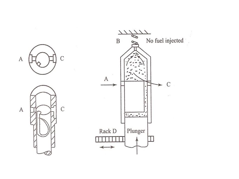
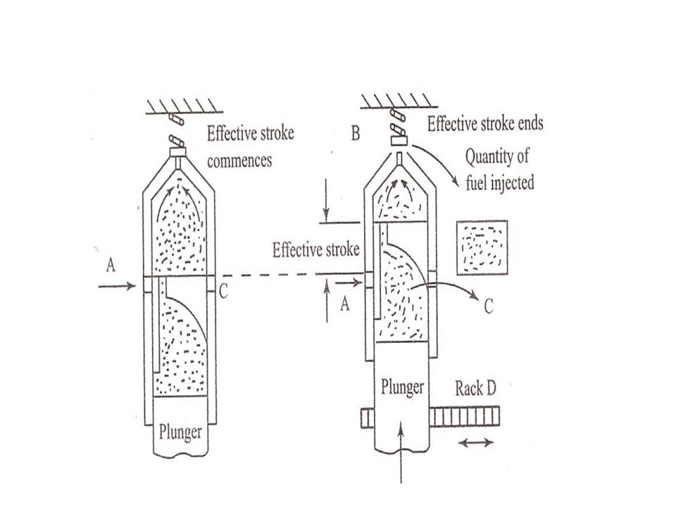
Jerk type fuel pump From the fuel tank the fuel travels through filters, heaters, circulation pumps and booster pumps. The injector pump works off its own cam fitted to the camshaft. Thiscam is also responsible for the injection timing. This type pump is of the helicalcontrol type. Fuel fills the chamber above the plunger. As the plunger moves up itcovers the ports and forces the fuel to the injector. The helix design means that thespill port is then uncovered to allow excess fuel to drain away and also for the pressure to drop signalling the end of injection. A non return delivery valve is in place to stop fuel escaping back to the pump and maintains high pressure giving goodinjectionThe vertical slot in the plunger is in place so when the fuel cut off point is reached thefuel can return to the spill. In some designs of engine like the Sulzer for example thisis done via a spill valve allowing the excess to drain off.The amount of fuel delivery can be increased by changing the design of the helix. If the ports to end injection are uncovered later in the cycle this would allow more fuelto the injector. A double helix design would mean that the forces acting on the plunger would be balanced whilst wear would become equalised.The function of the Quadrant (pinion) and Control Rod (rack) is to control the motiono f the plunger thus dictating the movement of the helix. If these were out of alignment the range of fuel delivery would suffer. It would not be possible for acomplete shut off or full on delivery position depending on which side the miss-alignment is. The control rod is operated from the governor which controls the speedof the engine under loaded conditions.To set the timing of the pump a torch can be shined through the barrel with the plunger being operated. As it moves up the light will be cut evenly. If adjustment isneeded the screw can be turned. Another method is to set the engine at 15 degrees before TDC this is the start of the injection process. Light is shined through the barreland plunger raised when the light disappears we know the correct setting is reached.The sight window lets us observe the pump operating freely. The clearances of the plunger and barrel would need to be altered if a change in fuel is needed. For example if a change from Heavy Fuel to Diesel the Heavy Fuel clearances are greater than those for Diesel as it is not such a viscose fuel. If those clearances remain toogreat then leakage could occur so they should be tightened up
 and Control Rod (rack) is to control the motiono f the plunger thus dictating the movement of the helix. If these were out of alignment the range of fuel delivery would suffer. It would not be possible for acomplete shut off or full on delivery position depending on which side the miss-alignment is. The control rod is operated from the governor which controls the speedof the engine under loaded conditions.To set the timing of the pump a torch can be shined through the barrel with the plunger being operated. As it moves up the light will be cut evenly. If adjustment isneeded the screw can be turned. Another method is to set the engine at 15 degrees before TDC this is the start of the injection process. Light is shined through the barreland plunger raised when the light disappears we know the correct setting is reached.The sight window lets us observe the pump operating freely. The clearances of the plunger and barrel would need to be altered if a change in fuel is needed. For example if a change from Heavy Fuel to Diesel the Heavy Fuel clearances are greater than those for Diesel as it is not such a viscose fuel. If those clearances remain toogreat then leakage could occur so they should be tightened up.")
32
Injection pumps Jerk type pump : consists of a reciprocating plunger inside a barrel . The plunger is driven by a camshaft.

33
Injection pumps

34
Injection pumps

38
Jerk type pump

39
Injection pumps Distributor type pump : The pump has only a single pumping element and the fuel is distributed to each cylinder by means of a rotor. There is a central longitudinal passage in the rotor and also two sets of radial holes ( each equal to the number of engine cylinders) located at different heights. One set is connected to pump inlet via central passage whereas the second set is connected to delivery lines leading to injectors of the various cylinders. Fuel is drawn into the central rotor passage from the inlet port when the pump plunger move away from each other. Whenever, the radial delivery passage in the rotor coincides with the delivery port, the fuel is delivered to that cylinder. Advantage : small size and light weight
 located at different heights. One set is connected to pump inlet via central passage whereas the second set is connected to delivery lines leading to injectors of the various cylinders. Fuel is drawn into the central rotor passage from the inlet port when the pump plunger move away from each other. Whenever, the radial delivery passage in the rotor coincides with the delivery port, the fuel is delivered to that cylinder. Advantage : small size and light weight.")
40
Distributor type pump

41
Fuel Injector

42
Nozzle that part of an injector through which the liquid fuel is sprayed into combustion chamber Functions : (i) Atomization : (ii) Distribution of fuel within combustion chamber – factors affecting these are : (a) injection pressure - higher the pressure, better the dispersion and penetration of fuel (b) Density of air in the cylinder- if the density of compressed air in the combustion chamber is high then the resistance to the movement of the droplets is higher and dispersion (spreading) of fuel is better (c) Physical properties of fuel – self ignition temperature, vapor pressure, viscosity etc play an important role in the distribution of fuel (iii) Prevention of impingement on walls : necessary because fuel striking the walls decomposes and produces carbon deposits. This causes smoky exhaust as well increase in fuel consumption. (iv) Mixing : mixing the fuel and air in case of non turbulent type of combustion chamber should be taken care by nozzle.
 Atomization : (ii) Distribution of fuel within combustion chamber – factors affecting these are : (a) injection pressure - higher the pressure, better the dispersion and penetration of fuel. (b) Density of air in the cylinder- if the density of compressed air in the combustion chamber is high then the resistance to the movement of the droplets is higher and dispersion (spreading) of fuel is better. (c) Physical properties of fuel – self ignition temperature, vapor pressure, viscosity etc play an important role in the distribution of fuel. (iii) Prevention of impingement on walls : necessary because fuel striking the walls decomposes and produces carbon deposits. This causes smoky exhaust as well increase in fuel consumption. (iv) Mixing : mixing the fuel and air in case of non turbulent type of combustion chamber should be taken care by nozzle.")
43
Types of Nozzle 1. Pintle Nozzle 2. Single hole Nozzle
3. Multi-hole Nozzle 4. Pintaux Nozzle

44
Types of Nozzle Pintle Nozzle:
The stem of the nozzle valve is extended to form a pin or pintle which protrudes through the mouth of the nozzle. The size and shape of the pintle can be varied according to the requirement. it provides a spray operating at low injection pressure of 8-10 Mpa. The spray cone angle is 60o . Advantage: It avoids weak injection and dribbling. It prevents the carbon deposition in the nozzle hole.

45
Pintle Nozzle

46
Types of Nozzle Single hole nozzle:
At the centre of the nozzle there is a single hole which is closed by nozzle valve. The size of the hole is usually of the order of 0.2 mm. Injection pressure in the order of Mpa. Spray Cone angle is 15o . Disadvantage: They tend to dribbling. Their spray angle is too narrow to facilitate good mixing unless higher velocities are used.

47
Single hole nozzle

48
Types of Nozzle Multi hole nozzle: It consists of a number of holes bored at the tip of the nozzle. The number of holes of varied from 4 to 18. The size of the hole are varies in the range of 35 to 200 µm. The hole angle may be from 20o upwards . These nozzle operate at higher pressures of the order of 18 Mpa. Advantages: lies in the ability to distribute the fuel properly even with lower air motion available in open combustion chambers

49
Multi hole nozzle

50
Types of Nozzle Pintaux Nozzle: It is a type of Pintle nozzle which has an auxiliary hole drilled in the nozzle body. It injects a small amount of fuel through this additional hole (Pilot injection) in the upstream direction slightly before the main injection . The nozzle valve does not lift fully at low speeds and most of the fuel is injected through the auxiliary hole. Advantages: Better cold starting performance.(20 to 25o C . Disadvantage: Injection characteristics are poorer than the multi hole nozzle
 in the upstream direction slightly before the main injection . The nozzle valve does not lift fully at low speeds and most of the fuel is injected through the auxiliary hole. Advantages: Better cold starting performance.(20 to 25o C . Disadvantage: Injection characteristics are poorer than the multi hole nozzle")
51
Pintaux Nozzle

Similar presentations


>")

