Download presentation
Presentation is loading. Please wait.

1
LESSON ELEVEN

2
FUEL OIL SYSTEM

3
1.FUEL OILS

4
1.H.F.O.

5
1.FUEL OILS 1.H.F.O. Heavy fuel oil ( residual, blends & crudes );
;")
6
1.FUEL OILS 1.H.F.O. Heavy fuel oil ( residual, blends & crudes ); 2.D.F.O.
; 2.D.F.O.")
7
1.FUEL OILS 1.H.F.O. Heavy fuel oil ( residual, blends & crudes ); 2.D.F.O. Diesel fuel oil or M.D.O. Marine Diesel oil or light fuel oil ( in restricted sense )
.")
8
1.FUEL OILS 1.H.F.O. Heavy fuel oil ( residual, blends & crudes ); 2.D.F.O. Diesel fuel oil or M.D.O. Marine Diesel oil or light fuel oil ( in restricted sense ) 1.1.1 Residuals
 Residuals.")
9
1.FUEL OILS 1.H.F.O. Heavy fuel oil ( residual, blends & crudes ); 2.D.F.O. Diesel fuel oil or M.D.O. Marine Diesel oil or light fuel oil ( in restricted sense ) 1.1.1 Residuals are residues from various rafinery processes;
 Residuals are residues from various rafinery processes;.")
10
1.FUEL OILS 1.H.F.O. Heavy fuel oil ( residual, blends & crudes ); 2.D.F.O. Diesel fuel oil or M.D.O. Marine Diesel oil or light fuel oil ( in restricted sense ) 1.1.1 Residuals are residues from various rafinery processes; 1.1.2 Blends
 Residuals are residues from various rafinery processes; Blends.")
11
1.FUEL OILS 1.H.F.O. Heavy fuel oil ( residual, blends & crudes ); 2.D.F.O. Diesel fuel oil or M.D.O. Marine Diesel oil or light fuel oil ( in restricted sense ) 1.1.1 Residuals are residues from various rafinery processes; 1.1.2 Blends are fuel oil mixtures of different viscosity to obtain a product of desired viscosity and density.
 Residuals are residues from various rafinery processes; Blends are fuel oil mixtures of different viscosity to obtain a product of desired viscosity and density..")
12
1.FUEL OILS 1.H.F.O. Heavy fuel oil ( residual, blends & crudes ); 2.D.F.O. Diesel fuel oil or M.D.O. Marine Diesel oil or light fuel oil ( in restricted sense ) 1.1.1 Residuals are residues from various rafinery processes; 1.1.2 Blends are fuel oil mixtures of different viscosity to obtain a product of desired viscosity and density. 1.1.3 Crudes:
 Residuals are residues from various rafinery processes; Blends are fuel oil mixtures of different viscosity to obtain a product of desired viscosity and density Crudes:.")
13
1.FUEL OILS 1.H.F.O. Heavy fuel oil ( residual, blends & crudes ); 2.D.F.O. Diesel fuel oil or M.D.O. Marine Diesel oil or light fuel oil ( in restricted sense ) 1.1.1 Residuals are residues from various rafinery processes; 1.1.2 Blends are fuel oil mixtures of different viscosity to obtain a product of desired viscosity and density. 1.1.3 Crudes: natural mixtures consisting of hydrocarbons + sulphur, nitrogen and / or oxygen derivatives of hydrocarbons.
 Residuals are residues from various rafinery processes; Blends are fuel oil mixtures of different viscosity to obtain a product of desired viscosity and density Crudes: natural mixtures consisting of hydrocarbons + sulphur, nitrogen and / or oxygen derivatives of hydrocarbons..")
14
1.FUEL OILS 1.H.F.O. Heavy fuel oil ( residual, blends & crudes ); 2.D.F.O. Diesel fuel oil or M.D.O. Marine Diesel oil or light fuel oil ( in restricted sense ) 1.1.1 Residuals are residues from various rafinery processes; 1.1.2 Blends are fuel oil mixtures of different viscosity to obtain a product of desired viscosity and density. 1.1.3 Crudes: natural mixtures consisting of hydrocarbons + sulphur, nitrogen and / or oxygen derivatives of hydrocarbons. 2. FUEL VISCOSITY
 Residuals are residues from various rafinery processes; Blends are fuel oil mixtures of different viscosity to obtain a product of desired viscosity and density Crudes: natural mixtures consisting of hydrocarbons + sulphur, nitrogen and / or oxygen derivatives of hydrocarbons. 2. FUEL VISCOSITY.")
15
1.FUEL OILS 1.H.F.O. Heavy fuel oil ( residual, blends & crudes ); 2.D.F.O. Diesel fuel oil or M.D.O. Marine Diesel oil or light fuel oil ( in restricted sense ) 1.1.1 Residuals are residues from various rafinery processes; 1.1.2 Blends are fuel oil mixtures of different viscosity to obtain a product of desired viscosity and density. 1.1.3 Crudes: natural mixtures consisting of hydrocarbons + sulphur, nitrogen and / or oxygen derivatives of hydrocarbons. 2. FUEL VISCOSITY Internal resistance of a fluid to relative movement. Oil is more viscous when cold. Viscosity is measured in Redwood Universal, Saybolt Universal, Saybolt Furol and Engler, but most commonly in kinematic cSt.
 Residuals are residues from various rafinery processes; Blends are fuel oil mixtures of different viscosity to obtain a product of desired viscosity and density Crudes: natural mixtures consisting of hydrocarbons + sulphur, nitrogen and / or oxygen derivatives of hydrocarbons. 2. FUEL VISCOSITY Internal resistance of a fluid to relative movement. Oil is more viscous when cold. Viscosity is measured in Redwood Universal, Saybolt Universal, Saybolt Furol and Engler, but most commonly in kinematic cSt..")
16
3. PURPOSE OF THE FUEL OIL SYSTEM

17
To store, transfer & clean the oil prior to injection.

18
3. PURPOSE OF THE FUEL OIL SYSTEM To store, transfer & clean the oil prior to injection. 4. SEPARATE FUEL OIL SYSTEMS

19
3. PURPOSE OF THE FUEL OIL SYSTEM To store, transfer & clean the oil prior to injection. 4. SEPARATE FUEL OIL SYSTEMS 4.1 H.F.O.

20
3. PURPOSE OF THE FUEL OIL SYSTEM To store, transfer & clean the oil prior to injection. 4. SEPARATE FUEL OIL SYSTEMS 4.1 H.F.O. Heavy fuel oil → in navigation;

21
3. PURPOSE OF THE FUEL OIL SYSTEM To store, transfer & clean the oil prior to injection. 4. SEPARATE FUEL OIL SYSTEMS 4.1 H.F.O. Heavy fuel oil → in navigation; 4.2 D.F.O.

22
3. PURPOSE OF THE FUEL OIL SYSTEM To store, transfer & clean the oil prior to injection. 4. SEPARATE FUEL OIL SYSTEMS 4.1 H.F.O. Heavy fuel oil → in navigation; 4.2 D.F.O. Diesel fuel oil / or M.D.O. Marine Diesel oil / or light fuel oil → in manuvering.

23
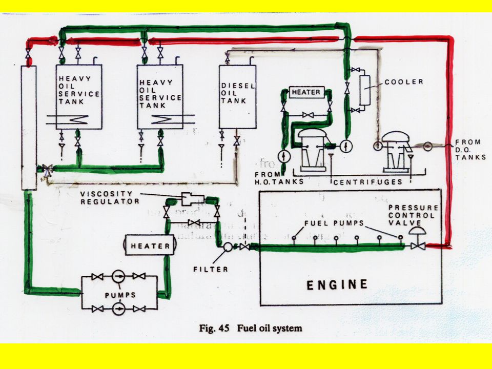
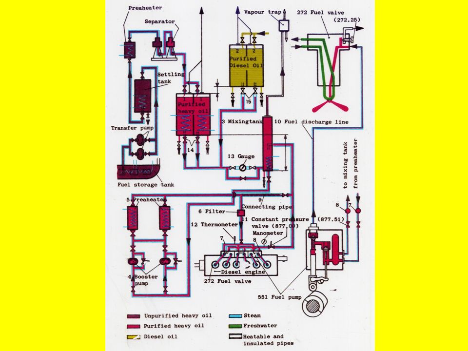
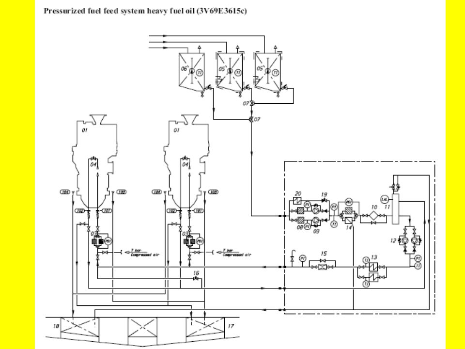
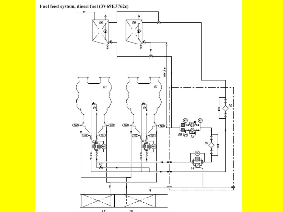
5. FROM THE DOUBLE BOTTOM TO THE ENGINE

25
5.1 Oil is taken from the double bottom tanks and pumped into a settling tank.

26
5. FROM THE DOUBLE BOTTOM TO THE ENGINE 5.1 Oil is taken from the double bottom tanks and pumped into a settling tank. 5.2 Then it is heated in the settling tank ( the sediment and the water are drawn off. )
.")
27
5. FROM THE DOUBLE BOTTOM TO THE ENGINE 5.1 Oil is taken from the double bottom tanks and pumped into a settling tank. 5.2 Then it is heated in the settling tank ( the sediment and the water are drawn off. ) 5.3 Next, the fuel is purified in a centrifuge ( a centrifuge is a unit usually consisting of a purifier and a clarifier.)
 5.3 Next, the fuel is purified in a centrifuge ( a centrifuge is a unit usually consisting of a purifier and a clarifier.).")
28
5. FROM THE DOUBLE BOTTOM TO THE ENGINE 5.1 Oil is taken from the double bottom tanks and pumped into a settling tank. 5.2 Then it is heated in the settling tank ( the sediment and the water are drawn off. ) 5.3 Next, the fuel is purified in a centrifuge ( a centrifuge is a unit usually consisting of a purifier and a clarifier.) 5.3.1. A purifier eliminates contaminants and a clarifier eliminates high density impurities).
 5.3 Next, the fuel is purified in a centrifuge ( a centrifuge is a unit usually consisting of a purifier and a clarifier.) A purifier eliminates contaminants and a clarifier eliminates high density impurities)..")
29
5. FROM THE DOUBLE BOTTOM TO THE ENGINE 5.1 Oil is taken from the double bottom tanks and pumped into a settling tank. 5.2 Then it is heated in the settling tank ( the sediment and the water are drawn off. ) 5.3 Next, the fuel is purified in a centrifuge ( a centrifuge is a unit usually consisting of a purifier and a clarifier.) 5.3.1. A purifier eliminates contaminants and a clarifier eliminates high density impurities). 5.4 Then it is admitted into a service tank.
 5.3 Next, the fuel is purified in a centrifuge ( a centrifuge is a unit usually consisting of a purifier and a clarifier.) A purifier eliminates contaminants and a clarifier eliminates high density impurities). 5.4 Then it is admitted into a service tank..")
30
5. FROM THE DOUBLE BOTTOM TO THE ENGINE 5.1 Oil is taken from the double bottom tanks and pumped into a settling tank. 5.2 Then it is heated in the settling tank ( the sediment and the water are drawn off. ) 5.3 Next, the fuel is purified in a centrifuge ( a centrifuge is a unit usually consisting of a purifier and a clarifier.) 5.3.1. A purifier eliminates contaminants and a clarifier eliminates high density impurities). 5.4 Then it is admitted into a service tank. 5.5 From the service tank the oil is passed through a heated buffer tank to the booster pumps ( or fuel delivery pump ).
 5.3 Next, the fuel is purified in a centrifuge ( a centrifuge is a unit usually consisting of a purifier and a clarifier.) A purifier eliminates contaminants and a clarifier eliminates high density impurities). 5.4 Then it is admitted into a service tank. 5.5 From the service tank the oil is passed through a heated buffer tank to the booster pumps ( or fuel delivery pump )..")
31
5. FROM THE DOUBLE BOTTOM TO THE ENGINE 5.1 Oil is taken from the double bottom tanks and pumped into a settling tank. 5.2 Then it is heated in the settling tank ( the sediment and the water are drawn off. ) 5.3 Next, the fuel is purified in a centrifuge ( a centrifuge is a unit usually consisting of a purifier and a clarifier.) 5.3.1. A purifier eliminates contaminants and a clarifier eliminates high density impurities). 5.4 Then it is admitted into a service tank. 5.5 From the service tank the oil is passed through a heated buffer tank to the booster pumps ( or fuel delivery pump ). 5.5.1 Buffer tank or a mixing tank:
 5.3 Next, the fuel is purified in a centrifuge ( a centrifuge is a unit usually consisting of a purifier and a clarifier.) A purifier eliminates contaminants and a clarifier eliminates high density impurities). 5.4 Then it is admitted into a service tank. 5.5 From the service tank the oil is passed through a heated buffer tank to the booster pumps ( or fuel delivery pump ) Buffer tank or a mixing tank:.")
32
5. FROM THE DOUBLE BOTTOM TO THE ENGINE 5.1 Oil is taken from the double bottom tanks and pumped into a settling tank. 5.2 Then it is heated in the settling tank ( the sediment and the water are drawn off. ) 5.3 Next, the fuel is purified in a centrifuge ( a centrifuge is a unit usually consisting of a purifier and a clarifier.) 5.3.1. A purifier eliminates contaminants and a clarifier eliminates high density impurities). 5.4 Then it is admitted into a service tank. 5.5 From the service tank the oil is passed through a heated buffer tank to the booster pumps ( or fuel delivery pump ). 5.5.1 Buffer tank or a mixing tank: a) H.F.O. and M.D.O. are mixed in it;
 5.3 Next, the fuel is purified in a centrifuge ( a centrifuge is a unit usually consisting of a purifier and a clarifier.) A purifier eliminates contaminants and a clarifier eliminates high density impurities). 5.4 Then it is admitted into a service tank. 5.5 From the service tank the oil is passed through a heated buffer tank to the booster pumps ( or fuel delivery pump ) Buffer tank or a mixing tank: a) H.F.O. and M.D.O. are mixed in it;.")
33
5. FROM THE DOUBLE BOTTOM TO THE ENGINE 5.1 Oil is taken from the double bottom tanks and pumped into a settling tank. 5.2 Then it is heated in the settling tank ( the sediment and the water are drawn off. ) 5.3 Next, the fuel is purified in a centrifuge ( a centrifuge is a unit usually consisting of a purifier and a clarifier.) 5.3.1. A purifier eliminates contaminants and a clarifier eliminates high density impurities). 5.4 Then it is admitted into a service tank. 5.5 From the service tank the oil is passed through a heated buffer tank to the booster pumps ( or fuel delivery pump ). 5.5.1 Buffer tank or a mixing tank: a) H.F.O. and M.D.O. are mixed in it; b) it recives a surplus fuel not consumed by engine
 5.3 Next, the fuel is purified in a centrifuge ( a centrifuge is a unit usually consisting of a purifier and a clarifier.) A purifier eliminates contaminants and a clarifier eliminates high density impurities). 5.4 Then it is admitted into a service tank. 5.5 From the service tank the oil is passed through a heated buffer tank to the booster pumps ( or fuel delivery pump ) Buffer tank or a mixing tank: a) H.F.O. and M.D.O. are mixed in it; b) it recives a surplus fuel not consumed by engine.")
34
5. FROM THE DOUBLE BOTTOM TO THE ENGINE 5.1 Oil is taken from the double bottom tanks and pumped into a settling tank. 5.2 Then it is heated in the settling tank ( the sediment and the water are drawn off. ) 5.3 Next, the fuel is purified in a centrifuge ( a centrifuge is a unit usually consisting of a purifier and a clarifier.) 5.3.1. A purifier eliminates contaminants and a clarifier eliminates high density impurities). 5.4 Then it is admitted into a service tank. 5.5 From the service tank the oil is passed through a heated buffer tank to the booster pumps ( or fuel delivery pump ). 5.5.1 Buffer tank or a mixing tank: a) H.F.O. and M.D.O. are mixed in it; b) it recives a surplus fuel not consumed by engine 5.6 Eventualy it is discharged into injection system through a fuel heater, viscosity regulator and a fine filter.
 5.3 Next, the fuel is purified in a centrifuge ( a centrifuge is a unit usually consisting of a purifier and a clarifier.) A purifier eliminates contaminants and a clarifier eliminates high density impurities). 5.4 Then it is admitted into a service tank. 5.5 From the service tank the oil is passed through a heated buffer tank to the booster pumps ( or fuel delivery pump ) Buffer tank or a mixing tank: a) H.F.O. and M.D.O. are mixed in it; b) it recives a surplus fuel not consumed by engine 5.6 Eventualy it is discharged into injection system through a fuel heater, viscosity regulator and a fine filter..")
41
6. SAFETY DEVICES

42
6.1 Low tank level alarm signals that a level in the tank is too low.

43
6. SAFETY DEVICES 6.1 Low tank level alarm signals that a level in the tank is too low. 6.2 Pressure loss alarm indicates a pressure drop below permissible limits.

44
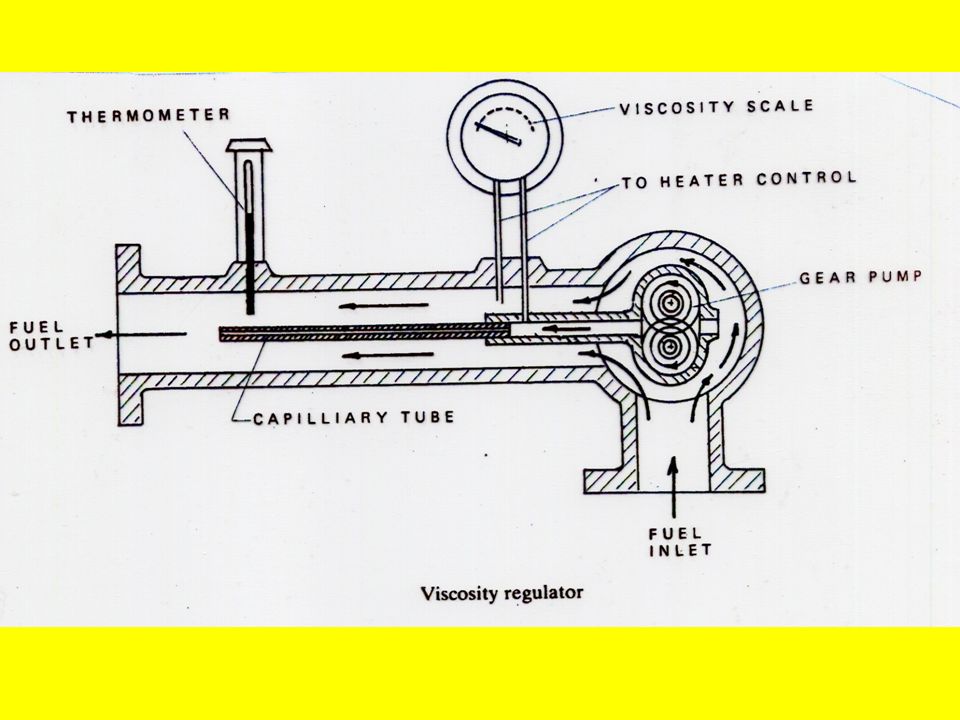
6. SAFETY DEVICES 6.1 Low tank level alarm signals that a level in the tank is too low. 6.2 Pressure loss alarm indicates a pressure drop below permissible limits. 6.3 Viscosity regulator* controls fuel oil temperature, i.e. viscosity)
.")
46
6. SAFETY DEVICES 6.1 Low tank level alarm signals that a level in the tank is too low. 6.2 Pressure loss alarm indicates a pressure drop below permissible limits. 6.3 Viscosity regulator* controls fuel oil temperature, i.e. viscosity) 6.4 Pressure regulating valve ensures constant pressure at the fuel main;
 6.4 Pressure regulating valve ensures constant pressure at the fuel main;.")
47
6. SAFETY DEVICES 6.1 Low tank level alarm signals that a level in the tank is too low. 6.2 Pressure loss alarm indicates a pressure drop below permissible limits. 6.3 Viscosity regulator* controls fuel oil temperature, i.e. viscosity) 6.4 Pressure regulating valve ensures constant pressure at the fuel main; 6.5 Quick close valves are valves having collapsable briage and may be closed from outside machinery space.
 6.4 Pressure regulating valve ensures constant pressure at the fuel main; 6.5 Quick close valves are valves having collapsable briage and may be closed from outside machinery space..")
48
6. SAFETY DEVICES 6.1 Low tank level alarm signals that a level in the tank is too low. 6.2 Pressure loss alarm indicates a pressure drop below permissible limits. 6.3 Viscosity regulator* controls fuel oil temperature, i.e. viscosity) 6.4 Pressure regulating valve ensures constant pressure at the fuel main; 6.5 Quick close valves are valves having collapsable briage and may be closed from outside machinery space. 6.6 Emergency remote cut-out switches fitted to the pumps and actuated in case of emergency.
 6.4 Pressure regulating valve ensures constant pressure at the fuel main; 6.5 Quick close valves are valves having collapsable briage and may be closed from outside machinery space. 6.6 Emergency remote cut-out switches fitted to the pumps and actuated in case of emergency..")
49
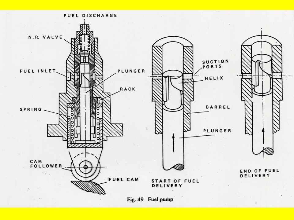
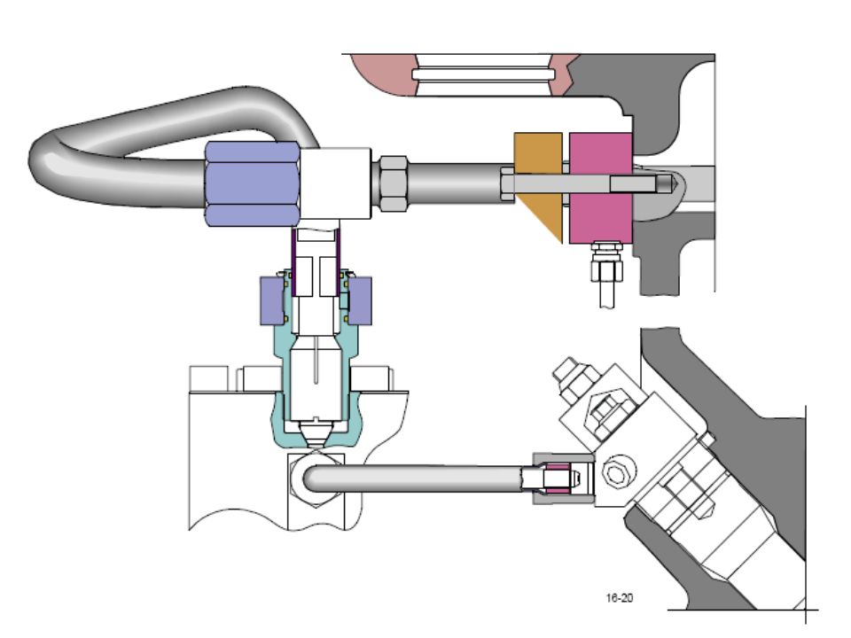
Gear pump rotates at about 40 rpm

50
Fuel inlet / supply is close to the heater discharge

51
Gear pump rotates at about 40 rpm Fuel inlet / supply is close to the heater discharge The fuel is discharged through a capillary tube

52
Gear pump rotates at about 40 rpm Fuel inlet / supply is close to the heater discharge The fuel is discharged through a capillary tube The pressure diference between each end of the tube is directly proportional to the viscosity of oil flowing through it.

53
Gear pump rotates at about 40 rpm Fuel inlet / supply is close to the heater discharge The fuel is discharged through a capillary tube The pressure diference between each end of the tube is directly proportional to the viscosity of oil flowing through it. Pressures are measured with Bourdon tubes and compared to read as viscosity.

54
Gear pump rotates at about 40 rpm Fuel inlet / supply is close to the heater discharge The fuel is discharged through a capillary tube The pressure diference between each end of the tube is directly proportional to the viscosity of oil flowing through it. Pressures are measured with Bourdon tubes and compared to read as viscosity. Pressures are fed to a differential presure transmitter which can automatically operate the heater control to maintain fuel viscosity within close limits

55
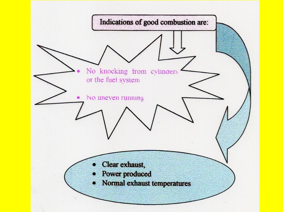
7. COMBUSTION

57
8. FACTORS LEADING TO GOOD COMBUSTION

58
8.1 VISCOSITY

59
8. FACTORS LEADING TO GOOD COMBUSTION 8.1 VISCOSITY It must be low enough to ensure correct atomisation at the fuel injection. When fuel oil is heated its viscosity is reduced.

60
8. FACTORS LEADING TO GOOD COMBUSTION 8.1 VISCOSITY It must be low enough to ensure correct atomisation at the fuel injection. When fuel oil is heated its viscosity is reduced. 8.2 ATOMISATION

61
8. FACTORS LEADING TO GOOD COMBUSTION 8.1 VISCOSITY It must be low enough to ensure correct atomisation at the fuel injection. When fuel oil is heated its viscosity is reduced. 8.2 ATOMISATION Is splitting up the fuel into very small droplets. The size of a droplet depends upon:

62
8. FACTORS LEADING TO GOOD COMBUSTION 8.1 VISCOSITY It must be low enough to ensure correct atomisation at the fuel injection. When fuel oil is heated its viscosity is reduced. 8.2 ATOMISATION Is splitting up the fuel into very small droplets. The size of a droplet depends upon: a) the atomizer holes;
 the atomizer holes;.")
63
8. FACTORS LEADING TO GOOD COMBUSTION 8.1 VISCOSITY It must be low enough to ensure correct atomisation at the fuel injection. When fuel oil is heated its viscosity is reduced. 8.2 ATOMISATION Is splitting up the fuel into very small droplets. The size of a droplet depends upon: a) the atomizer holes; b) pressure difference between the fuel pump
 the atomizer holes; b) pressure difference between the fuel pump.")
64
8. FACTORS LEADING TO GOOD COMBUSTION 8.1 VISCOSITY It must be low enough to ensure correct atomisation at the fuel injection. When fuel oil is heated its viscosity is reduced. 8.2 ATOMISATION Is splitting up the fuel into very small droplets. The size of a droplet depends upon: a) the atomizer holes; b) pressure difference between the fuel pump c) discharge and that of the compressed air in the combustion chamber.
 the atomizer holes; b) pressure difference between the fuel pump c) discharge and that of the compressed air in the combustion chamber..")
66
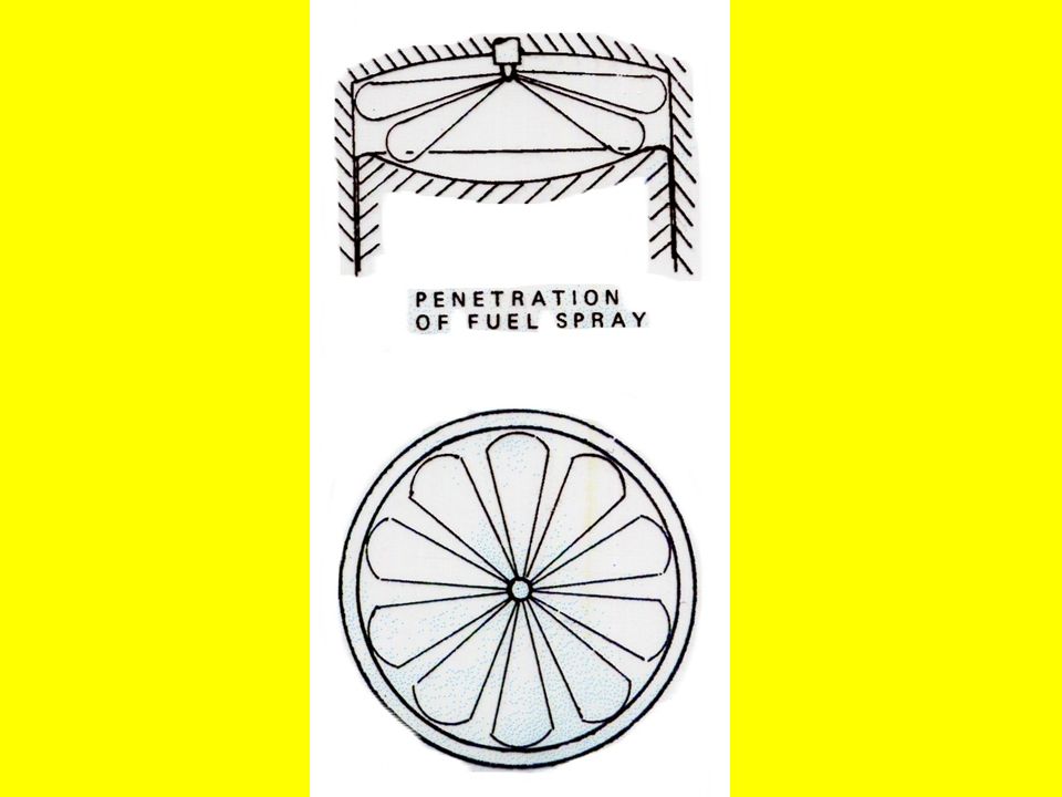
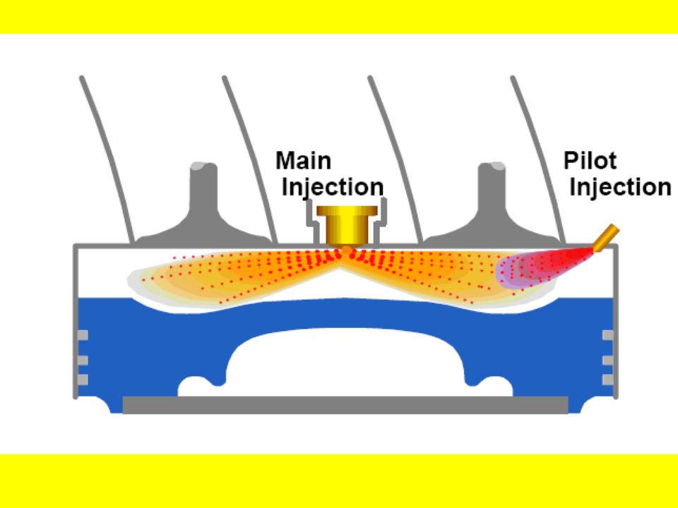
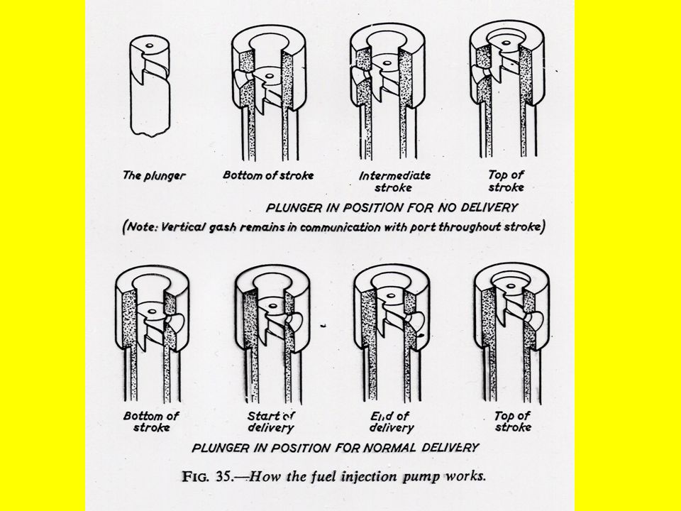
8.3 PENETRATION Is the distance the oil droplets travel into combustion space before mixing with air and igniting.

68
Penetration depends upon:

69
a) atomisation;
 atomisation;")
70
Penetration depends upon: a) atomisation; b) velocity leaving the injector
 atomisation; b) velocity leaving the injector")
71
Penetration depends upon: a) atomisation; b) velocity leaving the injector c) conditions within the combustion chamber
 atomisation; b) velocity leaving the injector c) conditions within the combustion chamber")
72
Penetration depends upon: a) atomisation; b) velocity leaving the injector c) conditions within the combustion chamber It is desirable that the fuel penetrates into the whole combustion space but it should not impinge on the internal surface before burning.
 atomisation; b) velocity leaving the injector c) conditions within the combustion chamber It is desirable that the fuel penetrates into the whole combustion space but it should not impinge on the internal surface before burning.")
73
Penetration depends upon: a) atomisation; b) velocity leaving the injector c) conditions within the combustion chamber It is desirable that the fuel penetrates into the whole combustion space but it should not impinge on the internal surface before burning. 8.4 TURBULENCE

74
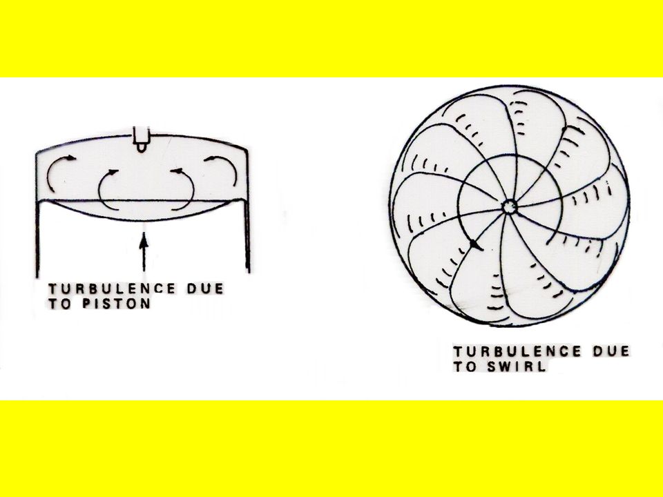
Penetration depends upon: a) atomisation; b) velocity leaving the injector c) conditions within the combustion chamber It is desirable that the fuel penetrates into the whole combustion space but it should not impinge on the internal surface before burning. 8.4 TURBULENCE Is the movement of the compressed air and fuel within a combustion space before combustion occurs.

76
Turbulence is caused by :

77
a) swirl, which is impared due to the air entry at scavange ports
 swirl, which is impared due to the air entry at scavange ports")
78
Turbulence is caused by : a) swirl, which is impared due to the air entry at scavange ports b) fuel spray pattern
 swirl, which is impared due to the air entry at scavange ports b) fuel spray pattern")
79
Turbulence is caused by : a) swirl, which is impared due to the air entry at scavange ports b) fuel spray pattern c) piston crown shape
 swirl, which is impared due to the air entry at scavange ports b) fuel spray pattern c) piston crown shape")
80
Turbulence is caused by : a) swirl, which is impared due to the air entry at scavange ports b) fuel spray pattern c) piston crown shape Turbulence improves fuel and air mixing for effective and rapid combustion.
 swirl, which is impared due to the air entry at scavange ports b) fuel spray pattern c) piston crown shape Turbulence improves fuel and air mixing for effective and rapid combustion.")
81
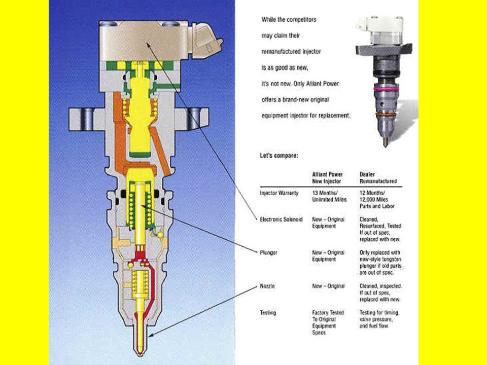
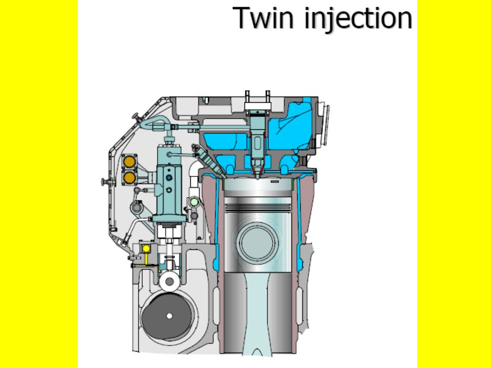
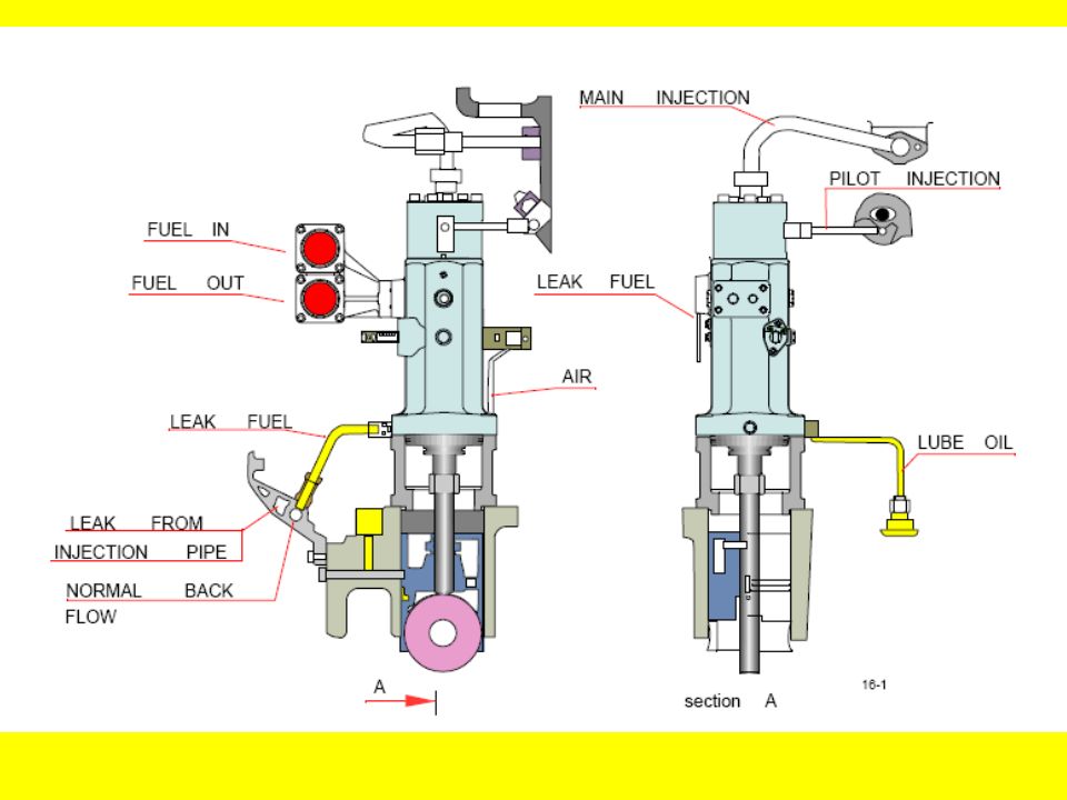
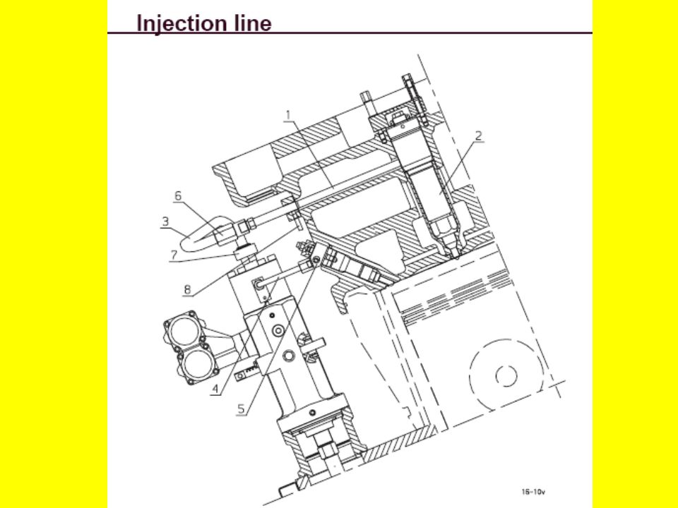
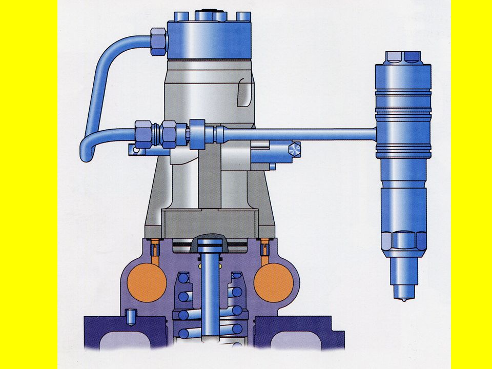
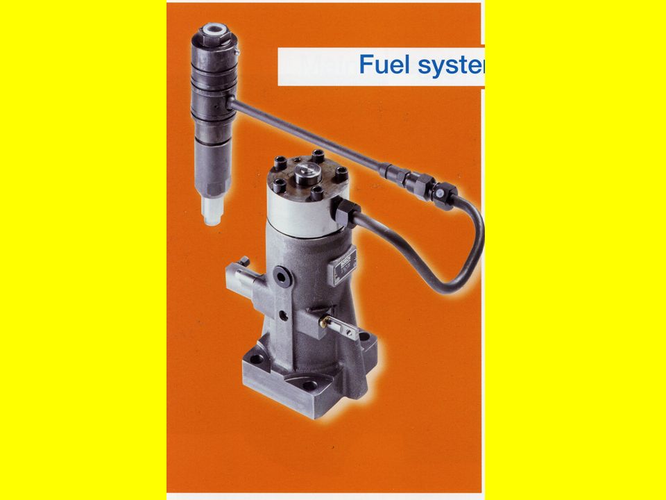
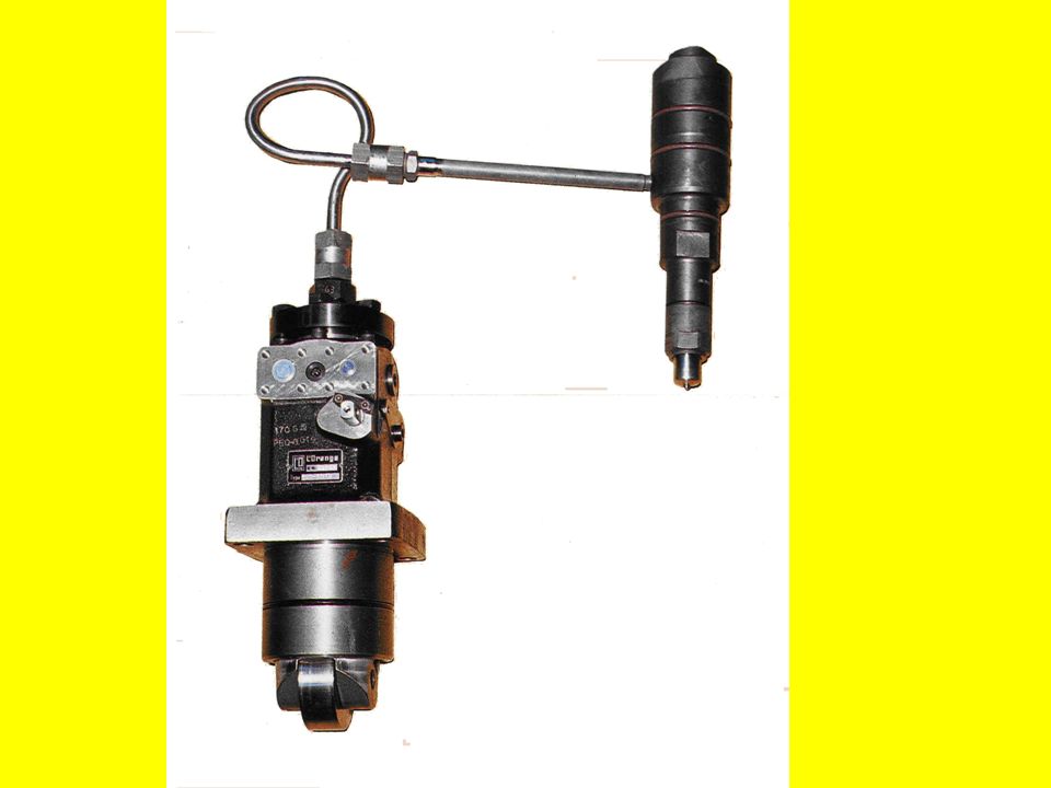
9. FUEL INJECTORS

84
They are inserted into fuel valve pocket of the engine cylinder.

85
9. FUEL INJECTORS They are inserted into fuel valve pocket of the engine cylinder. Injectors can be fitted centrally ( simetrical fuel spray ) or in other way depending upon the position of exhaust valves.
 or in other way depending upon the position of exhaust valves..")
88
9. FUEL INJECTORS They are inserted into fuel valve pocket of the engine cylinder. Injectors can be fitted centrally ( simetrical fuel spray ) or in other way depending upon the position of exhaust valves. Defects:
 or in other way depending upon the position of exhaust valves. Defects:.")
89
9. FUEL INJECTORS They are inserted into fuel valve pocket of the engine cylinder. Injectors can be fitted centrally ( simetrical fuel spray ) or in other way depending upon the position of exhaust valves. Defects: a) choking due to dirt;
 or in other way depending upon the position of exhaust valves. Defects: a) choking due to dirt;.")
90
9. FUEL INJECTORS They are inserted into fuel valve pocket of the engine cylinder. Injectors can be fitted centrally ( simetrical fuel spray ) or in other way depending upon the position of exhaust valves. Defects: a) choking due to dirt; b) inadeqate cooling ( high t. → carbon building up on the atomiser;) ( low t. → external corrosion )
 or in other way depending upon the position of exhaust valves. Defects: a) choking due to dirt; b) inadeqate cooling ( high t. → carbon building up on the atomiser;) ( low t. → external corrosion ).")
91
9. FUEL INJECTORS They are inserted into fuel valve pocket of the engine cylinder. Injectors can be fitted centrally ( simetrical fuel spray ) or in other way depending upon the position of exhaust valves. Defects: a) choking due to dirt; b) inadeqate cooling ( high t. → carbon building up on the atomiser;) ( low t. → external corrosion ) Testing:
 or in other way depending upon the position of exhaust valves. Defects: a) choking due to dirt; b) inadeqate cooling ( high t. → carbon building up on the atomiser;) ( low t. → external corrosion ) Testing:.")
92
9. FUEL INJECTORS They are inserted into fuel valve pocket of the engine cylinder. Injectors can be fitted centrally ( simetrical fuel spray ) or in other way depending upon the position of exhaust valves. Defects: a) choking due to dirt; b) inadeqate cooling ( high t. → carbon building up on the atomiser;) ( low t. → external corrosion ) Testing: Fuel injectors must be regulary overhauled;
 or in other way depending upon the position of exhaust valves. Defects: a) choking due to dirt; b) inadeqate cooling ( high t. → carbon building up on the atomiser;) ( low t. → external corrosion ) Testing: Fuel injectors must be regulary overhauled;.")
93
9. FUEL INJECTORS They are inserted into fuel valve pocket of the engine cylinder. Injectors can be fitted centrally ( simetrical fuel spray ) or in other way depending upon the position of exhaust valves. Defects: a) choking due to dirt; b) inadeqate cooling ( high t. → carbon building up on the atomiser;) ( low t. → external corrosion ) Testing: Fuel injectors must be regulary overhauled; After assembly an injector is tested with a test pump ( operating pressure and fuel spray );
 or in other way depending upon the position of exhaust valves. Defects: a) choking due to dirt; b) inadeqate cooling ( high t. → carbon building up on the atomiser;) ( low t. → external corrosion ) Testing: Fuel injectors must be regulary overhauled; After assembly an injector is tested with a test pump ( operating pressure and fuel spray );.")
94
9. FUEL INJECTORS They are inserted into fuel valve pocket of the engine cylinder. Injectors can be fitted centrally ( simetrical fuel spray ) or in other way depending upon the position of exhaust valves. Defects: a) choking due to dirt; b) inadeqate cooling ( high t. → carbon building up on the atomiser;) ( low t. → external corrosion ) Testing: Fuel injectors must be regulary overhauled; After assembly an injector is tested with a test pump ( operating pressure and fuel spray ); There should be no leakages.
 or in other way depending upon the position of exhaust valves. Defects: a) choking due to dirt; b) inadeqate cooling ( high t. → carbon building up on the atomiser;) ( low t. → external corrosion ) Testing: Fuel injectors must be regulary overhauled; After assembly an injector is tested with a test pump ( operating pressure and fuel spray ); There should be no leakages..")
95
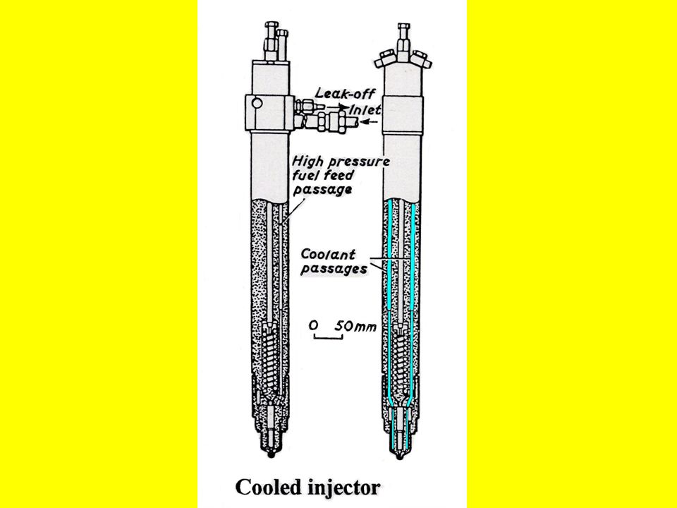
9.1 COOLING

96
By circulating water or oil through cooling passages.

97
9.1 COOLING By circulating water or oil through cooling passages. Heavy fuel injectors are fitted with water cooled nozzles.

98
9.1 COOLING By circulating water or oil through cooling passages. Heavy fuel injectors are fitted with water cooled nozzles. If there were no cooling, the nozzles would become too hot and liable to carbon deposits.

100
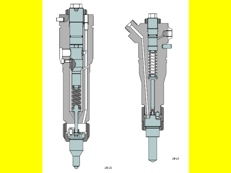
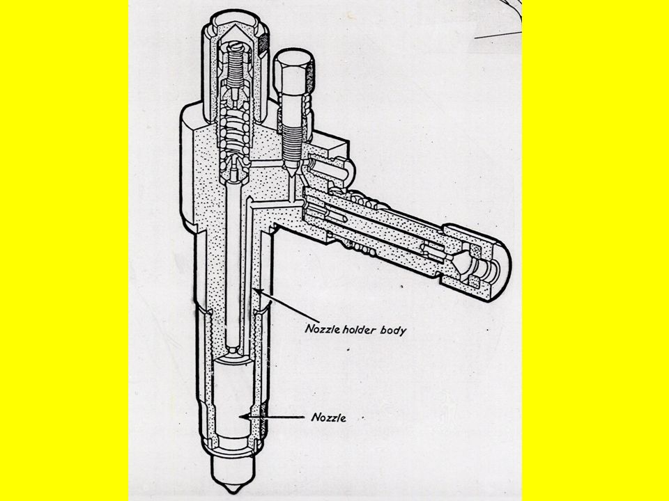
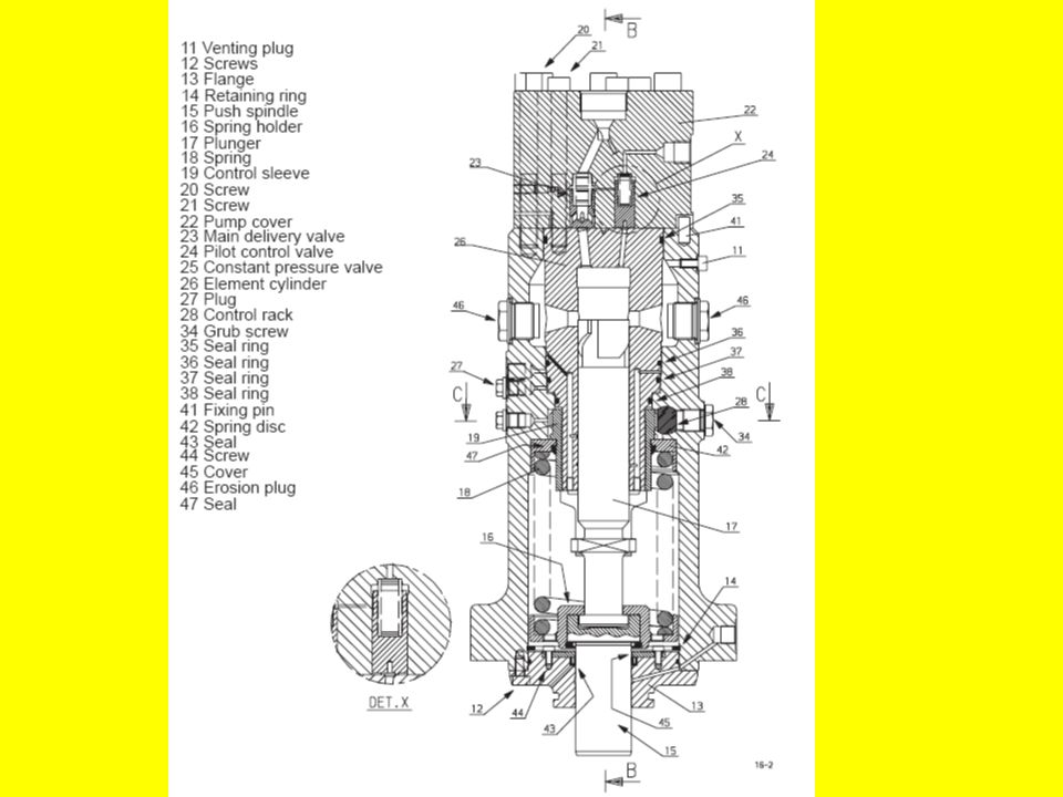
9.2 VALVE BODY OR NOZZLE HOLDER CONTAINS

101
spring,

102
9.2 VALVE BODY OR NOZZLE HOLDER CONTAINS spring, compression nut,

103
9.2 VALVE BODY OR NOZZLE HOLDER CONTAINS spring, compression nut, intermediate spindle,

104
9.2 VALVE BODY OR NOZZLE HOLDER CONTAINS spring, compression nut, intermediate spindle, fuel oil passages,

105
9.2 VALVE BODY OR NOZZLE HOLDER CONTAINS spring, compression nut, intermediate spindle, fuel oil passages, cooling passages

107
9.2 VALVE BODY OR NOZZLE HOLDER CONTAINS spring, compression nut, intermediate spindle, fuel oil passages, cooling passages The body of an injector has a hardened surface.

108
9.2 VALVE BODY OR NOZZLE HOLDER CONTAINS spring, compression nut, intermediate spindle, fuel oil passages, cooling passages The body of an injector has a hardened surface. The nozzle or atomiser is secured by a compression nut / retaining nut / spring adjusting nut.

109
9.2 VALVE BODY OR NOZZLE HOLDER CONTAINS spring, compression nut, intermediate spindle, fuel oil passages, cooling passages The body of an injector has a hardened surface. The nozzle or atomiser is secured by a compression nut / retaining nut / spring adjusting nut. A dowel is fitted to ensure that fuel oil passages and cooling water passages are aligned.

110
9.2 VALVE BODY OR NOZZLE HOLDER CONTAINS spring, compression nut, intermediate spindle, fuel oil passages, cooling passages The body of an injector has a hardened surface. The nozzle or atomiser is secured by a compression nut / retaining nut / spring adjusting nut. A dowel is fitted to ensure that fuel oil passages and cooling water passages are aligned. The needle valve and the atomiser are kept as one unit.

111
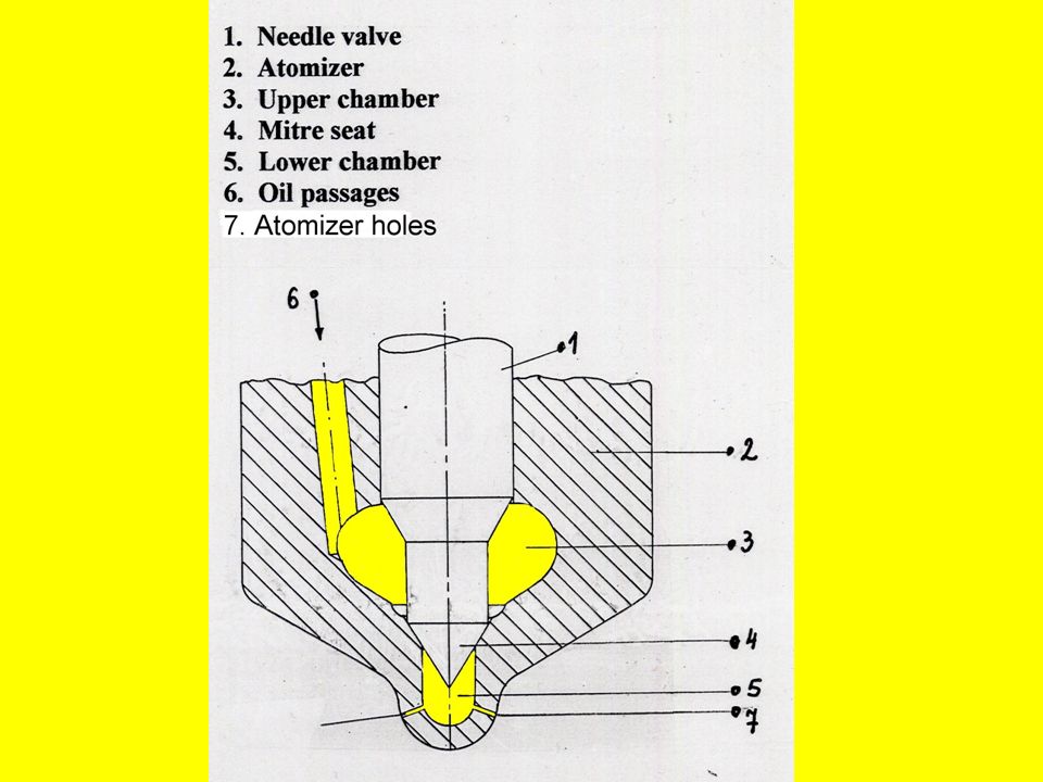
9.3 FUEL INJECTOR NEEDLE VALVE

113
Spring loaded non-return needle valve ( 1 ) is lapped in a bore of an atomiser ( 2 ).
 is lapped in a bore of an atomiser ( 2 ).")
114
9.3 FUEL INJECTOR NEEDLE VALVE Spring loaded non-return needle valve ( 1 ) is lapped in a bore of an atomiser ( 2 ). The pump supplies fuel oil through the oil fuel passage ( 6 ).
..")
115
9.3 FUEL INJECTOR NEEDLE VALVE Spring loaded non-return needle valve ( 1 ) is lapped in a bore of an atomiser ( 2 ). The pump supplies fuel oil through the oil fuel passage ( 6 ). The upper chamber ( 3 ) is charged with fuel and sealed by needle valve ( 1 ).
. The upper chamber ( 3 ) is charged with fuel and sealed by needle valve ( 1 )..")
116
9.3 FUEL INJECTOR NEEDLE VALVE Spring loaded non-return needle valve ( 1 ) is lapped in a bore of an atomiser ( 2 ). The pump supplies fuel oil through the oil fuel passage ( 6 ). The upper chamber ( 3 ) is charged with fuel and sealed by needle valve ( 1 ). The lower chamber ( 5 ) is sealed with mitre seat ( 4 ), also making an effective oil seal.
. The upper chamber ( 3 ) is charged with fuel and sealed by needle valve ( 1 ). The lower chamber ( 5 ) is sealed with mitre seat ( 4 ), also making an effective oil seal..")
117
9.3 FUEL INJECTOR NEEDLE VALVE Spring loaded non-return needle valve ( 1 ) is lapped in a bore of an atomiser ( 2 ). The pump supplies fuel oil through the oil fuel passage ( 6 ). The upper chamber ( 3 ) is charged with fuel and sealed by needle valve ( 1 ). The lower chamber ( 5 ) is sealed with mitre seat ( 4 ), also making an effective oil seal. Atomiser holes ( 7 ) are used for discharging the fuel through them at a high pressure.
. The upper chamber ( 3 ) is charged with fuel and sealed by needle valve ( 1 ). The lower chamber ( 5 ) is sealed with mitre seat ( 4 ), also making an effective oil seal. Atomiser holes ( 7 ) are used for discharging the fuel through them at a high pressure..")
120
9.4 NOZZLES

121
9.4.1. Purpose

122
9.4 NOZZLES 9.4.1. Purpose The fuel is injected at high velocity through small holes in the injector nozzle and the fine spray penetrates throughout the combustion chamber.

123
9.4 NOZZLES 9.4.1. Purpose The fuel is injected at high velocity through small holes in the injector nozzle and the fine spray penetrates throughout the combustion chamber. the injection must be sharp to avoid deterioration of spray into a dribble or jets.

124
9.4 NOZZLES 9.4.1. Purpose The fuel is injected at high velocity through small holes in the injector nozzle and the fine spray penetrates throughout the combustion chamber. the injection must be sharp to avoid deterioration of spray into a dribble or jets. 9.4.2. Opening pressure

125
9.4 NOZZLES 9.4.1. Purpose The fuel is injected at high velocity through small holes in the injector nozzle and the fine spray penetrates throughout the combustion chamber. the injection must be sharp to avoid deterioration of spray into a dribble or jets. 9.4.2. Opening pressure Usually about 600 bar ( for medium speed diesel engines)
.")
126
9.4 NOZZLES 9.4.1. Purpose The fuel is injected at high velocity through small holes in the injector nozzle and the fine spray penetrates throughout the combustion chamber. the injection must be sharp to avoid deterioration of spray into a dribble or jets. 9.4.2. Opening pressure Usually about 600 bar ( for medium speed diesel engines) 9.4.3 Types
 Types.")
127
9.4 NOZZLES 9.4.1. Purpose The fuel is injected at high velocity through small holes in the injector nozzle and the fine spray penetrates throughout the combustion chamber. the injection must be sharp to avoid deterioration of spray into a dribble or jets. 9.4.2. Opening pressure Usually about 600 bar ( for medium speed diesel engines) 9.4.3 Types Multi orifice type.
 Types Multi orifice type..")
128
9.4 NOZZLES 9.4.1. Purpose The fuel is injected at high velocity through small holes in the injector nozzle and the fine spray penetrates throughout the combustion chamber. the injection must be sharp to avoid deterioration of spray into a dribble or jets. 9.4.2. Opening pressure Usually about 600 bar ( for medium speed diesel engines) 9.4.3 Types Multi orifice type. The disposition of holes & their number depend upon the combustion chamber design.
 Types Multi orifice type. The disposition of holes & their number depend upon the combustion chamber design..")
Similar presentations


 Patel Vidhi A.>")


