Download presentation
Presentation is loading. Please wait.

1
REINFORCING DETAILING OF R.C.C MEMBERS
REINFORCEMENT DETAILING OF R.C.C MEMBERS PRESENTED BY: Er. Mahendra Kumar Samal, Dy. Executive Engineer REINFORCING DETAILING OF R.C.C MEMBERS

2
WHO IS AN ENGINEER? According to USA President Herbert Hoover, who was an engineer before he became a politician, said: The great liability of the engineer …compared to men of other professions……is that his works are out in the open where all can see them. His acts …..step by step …are in hard substances. He cannot bury his mistakes in the grave like the DOCTORS. He cannot argue them into thin air…..or blame the judge…..like the LAWYERS. He cannot, like the ARCHITECT, cover his figures with trees and vines. He cannot, like the politicians, screen his shortcomings by blaming his opponents….and hope the people will forget. The ENGINEER simply cannot deny he did it. If his works do not work……he is damned.

3
A design engineer’s responsibility should include assuring the structural safety of the design, details, checking shop drawing. Detailing is as important as design since proper detailing of engineering designs is an essential link in the planning and engineering process as some of the most devasting collapses in history have been caused by defective connections or DETAILING. There are many examples explained in the book" DESIGN AND CONSTRUCTION FAILURES by Dov Kaminetzky. Detailing is very important not only for the proper execution of the structures but for the safety of the structures. Detailing is necessary not only for the steel structures but also for the RCC members as it is the translation of all the mathematical expression’s and equation’s results.

4
For the RCC members for most commonly used for buildings we can divide the detailing for
SLABS-WITH OR WITHOUT OPENINGS (RECTANGULAR, CIRCULAR, NON-RECTANGULAR-PYRAMID SLAB, TRIANGULAR etc.) BALCONY SLAB, LOFT SLAB, CORNER SLAB etc. BEAMS- WITH OR WITHOUT OPENIGS.(SHALLOW & DEEP BEAMS) COLUMNS (RECTANGULAR, L-SHAPE, T-SHAPE, CIRCULAR, OCTAGONAL, CROSS SHAPE etc.) 4. FOUNDATIONS. Detailing for gravity loads is different from the lateral loads specially for the SEISMIC FORCES. Apart from the detailing for the above there is a different detailing required for the Rehabilitation and strengthening of damaged structures. We will now deal on the DETAILING OF MEMBERS FOR THE GRAVITY AND SOME CODAL DETAILINGS AS PER IS CODE IS AND IS AS REQUIRED FOR SEISMIC FORCES.
 BALCONY SLAB, LOFT SLAB, CORNER SLAB etc. BEAMS- WITH OR WITHOUT OPENIGS.(SHALLOW & DEEP BEAMS) COLUMNS (RECTANGULAR, L-SHAPE, T-SHAPE, CIRCULAR, OCTAGONAL, CROSS SHAPE etc.) 4. FOUNDATIONS. Detailing for gravity loads is different from the lateral loads specially for the SEISMIC FORCES. Apart from the detailing for the above there is a different detailing required for the Rehabilitation and strengthening of damaged structures. We will now deal on the DETAILING OF MEMBERS FOR THE GRAVITY AND SOME CODAL DETAILINGS AS PER IS CODE IS AND IS 4326 AS REQUIRED FOR SEISMIC FORCES.")
5
REINFORCEMENT DETAILING IN GENERAL
1. Prepare drawings properly & accurately if possible label each bar and show its shape for clarity. 12” I 1- Cross section of retaining wall which collapsed immediately after placing of soil backfill because ¼” rather than 1-1/4” dia. were used. Error occurred because Correct rebar dia. Was covered by a dimension line.

6
2. Prepare bar-bending schedule , if necessary.
Indicate proper cover; clear cover, nominal cover or effective cover to reinforcement. Decide detailed location of opening/hole and supply adequate details for reinforcements around the openings. Use commonly available size of bars and spirals. For a single structural member the number of different sizes of bars shall be kept minimum. 6. The grade of the steel shall be clearly stated in the drawing. 7. Deformed bars need not have hooks at their ends. 8. Show enlarged details at corners, intersections of walls, beams and column joint and at similar situations.

7
9. Congestion of bars should be avoided at points where members intersect and make certain that all reinforcement can be properly placed. 10. In the case of bundled bars, lapped splice of bundled bars shall be made by splicing one bar at a time; such individual splices within the bundle shall be staggered. Make sure that hooked and bent up bars can be placed and have adequate concrete protection.

8
12. Indicate all expansion, construction and contraction joints on plans and provide details for such joints. 13. The location of construction joints shall be at the point of minimum shear approximately at mid or near the mid points. It shall be formed vertically and not in a sloped manner.

9
FOUNDATION

10
FOOTING-DETAILS(INDEPENDENT)
INCORRECT COLUMN BARS STARTER BARS NATURAL G.L COVER TO STARTER Lb 3” SIDE COVER Ldt Min.300 COVER50mm IF p.c.c below or 75mm Ldt CORRECT

11
TYPICAL REIN DETAILS OF HAMMER FOUNDATION BLOCK
INCORRECT CORRECT Ld Ld

12
1. The minimum thickness of cover to main reinforcement shall not be less than 50mm.
However, where the concrete is in direct contact with the soil, for example, when a leveling course of lean concrete is not used at the bottom of the footing, it is usual to specify a cover of 75mm. In case of raft foundation, whether resting directly on soil or on lean concrete, the cover for the reinforcement shall not be less than 75mm. The cover of concrete overall the reinforcement including ties should not be less than 40mm for piles . But where the piles are exposed to sea water or water having other corrosive content, the cover should be no where less than 50mm. The minimum reinforcement for slab in footing in either direction shall not be less than 0.1 percentage of the gross sectional area for mild steel reinforcement and 0.12 percent in case of high strength deformed bars. The minimum area of tension reinforcement for beam in footing shall be as per the provisions applicable to beams.

13
7. The diameter of main reinforcing bars should be not less than 10mm.
Extended vertical reinforcement or dowels of at least 0.5 percent of the cross-sectional area of the supported column or pedestal with a minimum of 4 bars of 12mm diameter shall be provided. Where dowels are used, their diameter shall not exceed the diameter of column bars by more than 3mm. To achieve economy, the footings are sloped or stepped towards the edge satisfying the requirements for bending and punching shear. The thickness at the edges shall not be less than 15cm for footing on soils, nor less than 30cm above tops of piles in case of footing on piles. Where top reinforcement is required, provide chairs and edge U-bars to support it. The diameter of chairs should be at least 12mm and its spacing shall not be less than 30 times the diameter of supporting bars.

14
COLUMN

15
BEAM COLUMN JUNCTION-EXTERIOR COLUMN
INCORRECT CLOSED STPS 2”max U TYPE BARS Ld IN TENSION-Ld CORRECT

16
SPLICE DETAIL FOR COLUMN
COVER CLOSE SLOPE 1:6 S-SPACING CORRECT INCORRECT

17
INCORRECT CORRECT COLUMN DETAILS IN EQ REGIONS
First stirrups 50mm from beam face END REGION END REGION-h/6 or D or 450MM whichever is greater h b d D END REGION END REGION Spacing of shear rein. In columns Spacing of shear rein. In columns

18
REDUCTION COLUMN BOTH SIDES
INCORRECT SPLICE SLOPE 1:8 FROM BEAM BOTTOM 3NO.CLOSE TIES CLOSE STPS SPACIN <=75mm 3NO.CLOSE TIES CORRECT

19
TERMINATION OF COLUMN BARS INSIDE BEAM
INCORRECT Ld CORRECT

22
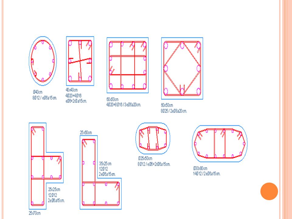
1. The cross-sectional area of longitudinal reinforcement, shall be not less than 0.8 percent nor more than 6 percent of the gross cross- sectional area of the column. 2. The minimum number of longitudinal bars provided in a column shall be four in rectangular columns & six in circular columns. 3. The bar shall not be less than 12mm in diameter. 4. A reinforced concrete column having helical reinforcement, at least 6 bars of longitudinal reinforcement within the helical reinforcement. 5. In a helically reinforced column, the longitudinal bars shall be in contact with the helical reinforcement and equidistant around its inner circumference. 6. Spacing of longitudinal bars measure along the periphery of the column shall not exceed 300mm. 7. Keep outer dimensions of column constant, as far as possible , for reuse of forms.

23
8. Preferably avoid use of 2 grades of vertical bars in the same element.
Bars larger than 36mm dia. Shall not be bundled. Lap splices shall be not be used for bars larger than 36mm dia. Except where welded. Where dowels are provided, their diameter shall not exceed the diameter of the column bars by more than 3mm. 10. Where bent up bars are provided, their contribution towards shear resistance shall not be more than 50% of the total shear to be resisted. Use of single bent up bars(cranked) are not allowed in the case of earthquake resistance structures. 11. The diameter of the polygonal links or lateral ties shall be not less than 1/4th of the diameter of the largest longitudinal bars and in no case less than 6mm. The pitch of the transverse reinforcement shall be not less than the least of the following distances:
 are not allowed in the case of earthquake resistance structures. 11. The diameter of the polygonal links or lateral ties shall be not less than 1/4th of the diameter of the largest longitudinal bars and in no case less than 6mm. 12. The pitch of the transverse reinforcement shall be not less than the least of the following distances:")
24
i) The least lateral dimension of the compression member
ii) 16times the smallest diameter of the longitudinal reinforcement bars to be tied. iii) 300 mm 13. For a longitudinal reinforcing bar in a column nominal cover shall in any case not be less than 40 mm, or less than the diameter of such bar. 14. In the case of columns of minimum dimension of 200 mm or under, whose reinforcing bars do not exceed 12 mm, a nominal cover of 25 mm may be used.
 16times the smallest diameter of the longitudinal reinforcement bars to be tied. iii) 300 mm. 13. For a longitudinal reinforcing bar in a column nominal cover shall in any case not be less than 40 mm, or less than the diameter of such bar. 14. In the case of columns of minimum dimension of 200 mm or under, whose reinforcing bars do not exceed 12 mm, a nominal cover of 25 mm may be used.")
25
BEAM AND SLAB

26
BEAM d INCORRECT d/2 d/2 CORRECT 1/4OR 1/5 SPAN d/2+d/2Cot(t) 1.5d Ld
LINE OF CRACK d/2 t d/2 t d/2+d/2Cot(t) 1.5d CORRECT
 1.5d. CORRECT.")
27
CANTILEVER BEAM Ld/2 Ld/2 Ld INCORRECT CLOSE STIRRUPS CORRECT Ldt
crack Ldt CLOSE STIRRUPS Ldt/2 Ld/2 Ld/2 Ld CORRECT

28
NON PRISMATIC BEAM Ld/2 Ld/2 Ld INCORRECT CLOSE STIRRUPS CORRECT Ldt
crack INCORRECT Ldt CLOSE STIRRUPS Ldt/2 Ld/2 Ld/2 CORRECT Ld

29
GRID BEAM GRID BEAM INCORRECT Hanger bars CORRECT Close rings 1.5d
300 300 d Hanger bars 2#extra bars CORRECT Slope 1:10

30
Details of Main & Secondary beams
Main beam INCORRECT Secondary beam Close rings 1.5d 1.5d 1.5d 300 300 d 60degree Hanger bars Main beam CORRECT

31
Continuous beam continuous beam incorrect correct Span/4 Span/4 Span/4
1.5d 1.5d 1.5d correct

32
CONTINUOUS BEAM L1 L2 INCORRECT L1 L2 CORRECT SPAN/4 SPAN/4 SPAN/4
100% CRACK 100% CRACK CRACK L1 .08L1 .08L1 L2 .08L2 INCORRECT 100% L1/4 L2/4 L1/4 20% 20% 0.1L1 100% 100% L1 .15L1 L2 .15L2 CORRECT

33
NONPRISMATIC SECTION OF BEAM
D CRACK D D INCORRECT CLOSE RING D D CORRECT D CLOSE RING

34
CANTILEVER BEAM PROJECTING FROM COLUMN
INCORRECT NOT LESS THAN 0.5Ast NOT LESS THAN GREATER OF 0.5L OR Ld 50mm Ld 0.25Ast COLUMN CORRECT Ld/3

35
SLOPING BEAM CRACK Ld Ld CORRECT

36
HAUNCH BEAMS L INCORRECT CORRECT L Ld Ld Ld Ld CRACK CRACK L/8 TO L/10

37
STRESSES AT CORNERS C-COMPRESSION T-TENSION C t C CRACK t
RESULTANT TENSILE STRESS FOR ACROSS CORNER(ONE PLANE) RESULTANT TENSILE STRESS FOR ACROSS CORNER(DIFFERENT PLANE) t CRACK c t c
 RESULTANT TENSILE STRESS FOR ACROSS CORNER(DIFFERENT PLANE) t. CRACK. c. t. c.")
38
SHEAR AND TORSION REIN. IN BEAMS
Stirrups taken round outermost bars spacing<=x1 <=(x1+y1)/4 <=300mm Min 0.2%bd to control deflection as well as for seismic requ. INCORRECT n d y1 Skin rein.10dia is required when depth exceeds 450mm(0.1% of web area distributed equally on two faces) D 100 to 200mm D-n>500mm D-n>500mm D/5 x1 CORRECT b
/4. <=300mm. Min 0.2%bd to control deflection as well as for seismic requ. INCORRECT. n. d. y1. Skin rein.10dia is required when depth exceeds 450mm(0.1% of web area distributed equally on two faces) D. 100 to 200mm. D-n>500mm. D-n>500mm. D/5. x1. CORRECT. b.")
39
CANTILEVER BEAM WITH POINT LOAD
Shear rein. INCORRECT 2/3d d Ld CORRECT Ld Extra ties

40
INCORRECT opening crack crack OPENING IN WEB OF BEAM d/2 opening d/2 Closed stps for d/2 Closed stps for d/2 Ld OPENING IN WEB OF BEAM CORRECT

41
EQ REGION-BEAM-COL JN-EXTERIOR
*COL.CORE HAS TO BE CONFINED BY CIRCULAR OR RECTANGULAR TIES IN ACCORDANCE WITH END REGION EQ REGION-BEAM-COL JN-EXTERIOR SPACING OF LATERAL TIES <=d/2 COL. CORE* END REGION SPACING OF LATERAL TIES <=100mm END REGION BEAM COL. JUNCTION-EQ REGION INCORRECT CORRECT SPACING OF LATERAL TIES <=d/2 SPACING OF LATERAL TIES <=d/2 BEAM COL. JUNCTION-EQ REGION

42
EQ-REGION-CONTINUOUS BEAM
INCORRECT 50mmmax CONTINUOUS BARS NOT LESS THAN ¼ AREA OF BARS AT COL.FACE CORRECT A=L1/3 A=L1/3 A=L1/3 Ld 2d 2d 2d 2d Stirrup spacing=d/4 or 100mm or 8dia which ever is the least

44
BEAMS : 1. The minimum area of tension reinforcement shall be not less than that given by the following: As = 0.85bd/ fy where As = minimum area of tension reinforcement b = breadth of beam/ the breadth of the web of T-beam d = effective depth fy =characteristic strength of reinforcement in N/mm² 2. The maximum area of tension reinforcement shall not exceed bD, where b is the width of the beam rib or web and D is the total depth of the beam. 3. The maximum area of compression reinforcement shall not exceed bD . 4. Where the depth of beams exceeds 750 mm in case of beams without torsion and 450 mm with torsion provide face reinforcement along the two faces. The total area of such reinforcement shall be not less than 0.1 percent of the web area and shall be distributed equally on two faces at a spacing not exceeding 300 mm or web thickness whichever is less. 5. The maximum spacing of shear reinforcement measured along the axis of the member shall not exceed 0.75 d for vertical stirrups and d for inclined stirrups at 45 degree, where d is the effective depth of the section. In no case shall the spacing exceed 300 mm.

45
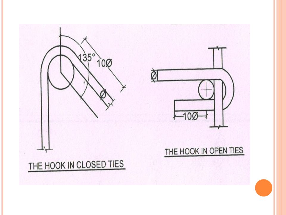
13. The hooks shall be bent to 135 degree .
6. At each end of reinforcing bar, net less that 25 mm or less than twice the diameter of the bar. 7. For longitudinal reinforcing bars in a beam, not less than 30 mm or less than the diameter of the bar. 8. Where splices are provided in bars, they shall be , as far as possible, away from the sections of maximum stresses and shall be staggered. 9. Deflection in slabs/beams may be reduced by providing compression reinforcement. 10. Only closed stirrups shall be used for transverse rein. For members subjected to torsion and for members likely to be subjected to reversal of stresses as in Seismic forces. 11. To accommodate bottom bars, it is good practice to make secondary beams shallower than main beams, at least by 50mm. 12. The stirrups shall be minimum size of 8mm in the case of lateral load resistance . 13. The hooks shall be bent to 135 degree .

46
SLABS: 1. The minimum reinforcement in either direction in slabs shall not be less than 0.15 percent of the total cross-sectional area in case of mild steel and 0.12 percent in case of high strength deformed bars. 2. The main bar in the slab shall not be less than 8 mm ( high yield strength bars) or 10 mm ( plain bars) and distribution steel shall not be less than 6 mm diameter bars . The diameter of the reinforcing bar shall not exceed one-eighth of the total thickness of the slab. 3. The horizontal distance between parallel reinforcement bars shall not be more than 3 times the effective depth of solid slab or 300 mm whichever is smaller. 4. The horizontal distance between parallel reinforcement bars provided against shrinkage and temperature shall not be more than 5 times the effective depth of a solid slab or 300 mm whichever is smaller. 5. The cover at each end of reinforcing bar shall be neither less than 25 mm nor less than twice the diameter of such bar. 6. The minimum cover to reinforcement ( tension, compression, shear) shall be not less than 15 mm, nor less than diameter of the bar.
 or 10 mm ( plain bars) and distribution steel shall not be less than 6 mm diameter bars . The diameter of the reinforcing bar shall not exceed one-eighth of the total thickness of the slab. 3. The horizontal distance between parallel reinforcement bars shall not be more than 3 times the effective depth of solid slab or 300 mm whichever is smaller. 4. The horizontal distance between parallel reinforcement bars provided against shrinkage and temperature shall not be more than 5 times the effective depth of a solid slab or 300 mm whichever is smaller. 5. The cover at each end of reinforcing bar shall be neither less than 25 mm nor less than twice the diameter of such bar. 6. The minimum cover to reinforcement ( tension, compression, shear) shall be not less than 15 mm, nor less than diameter of the bar.")
47
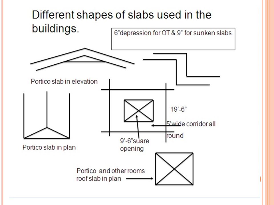
DETAILING OF SLABS WITHOUT ANY CUT OR OPENINGS.
The building plan DX-3 shows the slabs in different levels for the purpose of eliminating the inflow of rainwater into the room from the open terrace and also the sunken slab for toilet in first floor. The building plan DX-A3 is one in which the client asked the architect to provide opening all round. Minimum and max.reinforcement % in beams, slabs and columns as per codal provisions should be followed.

49
SECTION OF TRENCH INCORRECT INCORRECT CRACK CORRECT Ld Ld Ld

50
STAIRCASE-WITH WAIST SLAB
INCORRECT Extra bar Ld(min) Ld(min) Ld(min) CORRECT
 Ld(min) Ld(min) CORRECT.")
51
SLABLESS STAIRCASE Dist. Alternate 1 Main bar Main bar

52
SLABLESS STAIRCASE Main bar L=horizontal span Alternate 2 A=0.25L

53
DEVELOPMENT LENGTH OF BARS APPROXIMATELY USE 50Xdia FOR TENSION
FOR A CONCRETE GRADE M20 &STEEL STRENGTH Fy=415 SL. NO BAR DIA. TENSIONmm COMPRESSION REMARKS 1 8 376.0 301.0 2 10 470.0 3 12 564.0 451.0 4 16 752.0 602.0 5 20 940.0 6 22 1034.0 827.0 7 25 1175.0 28 1316.0 1053.0 9 32 1504.0 1203.0 APPROXIMATELY USE 50Xdia FOR TENSION

54
CONCLUSION: As there is no time to elaborately explaining ,the following topics are not covered : Flat slabs, Folded plates, shell structures-cylindrical shells, silos, Staircases- helical staircase, central beam type, cantilever type etc. Different types of foundations-raft, pile foundation, strap foundation etc. Retaining wall structures. Liquid retaining structures. Deep beams. Shear wall, walls. Hope that I have enlighten some of the detailing technique for the most commonly encountered RCC members in buildings.

55
REFERENCES: HANDBOOK ON CONCRETE REINFORCEMENT AND DETAILING-SP:34(S&T)-1987. MANUAL OF STANDARD PRACTICE –CONCRETE REINFORCING STEEL INSTITUTE. DESIGN PRINCIPLES AND DETAILING OF CONCRETE STRUCTURES. By D.S.PRAKASH RAO. DESIGN AND CONSTRUCTION FAILURES BY DOV KAMINETZKY. IS: CODE OF PRACTICE FOR BENDING AND FIXING OF BARS FOR CONCRETE REINFORCEMENT.

56
IS:13920:2002. IS:1893:2000. IS:4326. IS:456:2000 REINFORCED HAND BOOK BY REYNOLD.

57
THANK YOU

Similar presentations


 Pradip Paudel (M.Sc. in Structural Engineering)>")
