Download presentation
Presentation is loading. Please wait.

1
INS 324 STEEL STRUCTURES Chapter 1 INTRODUCTION Dr. KIVANÇ TAŞKIN

2
(Safety, economy, aesthetics, environment and sustainability)
1.2 STRUCTURAL DESIGN (Safety, economy, aesthetics, environment and sustainability) Structural design may be defined as a mixture of art and science, combining the experienced engineer’s intuitive feeling for the behaviour of a structure with a sound knowledge of principles of statics, dynamics, strength of materials and structural analysis, produce a safe economical structure which will serve its intended purpose. At the same time it is necessary to be sensitive to preserve environment and natural materials in structural design. So structural design should be safe, economic, aesthetic and sustainable.
 Structural design may be defined as a mixture of art and science, combining the experienced engineer’s intuitive feeling for the behaviour of a structure with a sound knowledge of principles of statics, dynamics, strength of materials and structural analysis, produce a safe economical structure which will serve its intended purpose. At the same time it is necessary to be sensitive to preserve environment and natural materials in structural design. So structural design should be safe, economic, aesthetic and sustainable.")
3
Responsibilities of the designer Safety
Structures must have enough strength, rigidity and toughness while they are used and at the same time they should have enough safety to overcome extra possible loads or loss of elements resistance. Provisions must be made for overload or understrength. In general, the expression for structural safety requirement may be written as, Left side represents the design resistance or strength and right side represents the factored loads. Φ: Resistance factor < 1 γ : Load factor >1

4
Failure of steel structures
Insufficient attention to the details of connections, erection problems, and foundation problems. To neglect some of the forces acting on the connection. Insufficient bearing or anchorage. Foundation settlements cause a large number of structural failures like cracks. Inadequate attention to deflection or vibration. For steel structures some structural failures occur because inadequate attention is given to , fatigue of members, bracing against swaying, stability of members or system, buckling of compression members, lateral buckling of beams. When structure is completed, it should be sufficiently braced with floors, walls, connections, and special bracing. During erection some special temporary bracing may be required.

5
Economy All the factors affecting the total cost of the structure have to be taken into consideration. And the designer needs to keep in mind the factors that can lower cost without sacrifice of strength. (The use of standard size members, simple connections and details, and members and materials that will not require an unreasonable amount of maintance through the years.) Aesthetics The structure should be aesthetic and in harmony with the environment. Appearance may often be the major factor in selecting the type of structure.
 Aesthetics. The structure should be aesthetic and in harmony with the environment. Appearance may often be the major factor in selecting the type of structure.")
6
Environment The construction and use of buildings, roads and bridges have an effect on the environment. “Natural resources are used to a minimum, energy is used economically and pollution is reduced.” The choice of materials by contractors; architects and engineers has ecological importance. It is essential to respect the environment, row materials and natural resources. The extraction and transport of row materials; the production and manufacture of construction materials; transport to the site; construction and its maintenance; and ability to recycle materials must be analyzed.

7
Sustainability Sustainability is “respond to the needs of the present without compromising the capacity of future generations to respond to theirs”. Human activities must become ecologically sustainable. The success of the project has to be measured on ecological, economic and social sustainability. For sustainability, cost of whole life cycle of the building should be calculated and evaluated with economy and environmental effects. Sustainable development means optimising the utilisation of row materials and energy during their entire life cycle, and reducing to a minimum any adverse effects on the environment.

8
1.2.1 Design procedure 1. Planning (Establishment of functions, general shape, layout of spaces, types of supports, accurate dimensions) 2. Preliminary structural configuration: Arrangement of elements 3. Establishment of loads 4. Preliminary design (Member selection, approximate sizes, rough details) 5. Analysis (Modelling, internal forces, deflections) 6. Evaluation (Strength and serviciability requirements) 7. Redesign (Repetition of any part) 8. Final decision (Safe and optimum design)
 5. Analysis (Modelling, internal forces, deflections) 6. Evaluation (Strength and serviciability requirements) 7. Redesign (Repetition of any part) 8. Final decision (Safe and optimum design)")
9
1.2.2 Material choice Major factors that may affect material choice are, Function of the structure, Soil conditions, Geographical location, Whether it is going to be permanent or temporary, Time period it is going to be in function, Determined date of operation, Funds dedicated to construction, Operational expenses, Changes in the costs of materials, Experience, local customs and habits.

10
Steel is an alloy and various properties of steel are determined by its chemical composition.
Principal component is iron and in much smaller amount carbon which contributes to strength but reduces ductility. Other components: Copper, manganese, nickel, chromium, molybdenum, silicon. Plain carbon steel: Mostly iron and carbon (less than 1%) Low-alloy steel: Iron and carbon plus other components (less than 5%) High-alloy or speciality steel: Similar to low alloy steel but higher percentage of the added components. 3. STRUCTURAL STEEL
 Low-alloy steel: Iron and carbon plus other components (less than 5%) High-alloy or speciality steel: Similar to low alloy steel but higher percentage of the added components. 3. STRUCTURAL STEEL.")
11
3.1 Mechanical properties
Homogenous and isotropic High strength High Young Modulus Equal tension and compression strength Ductile Tough

12
Homogenous and isotropic High strength
The properties of steel do not change with time, and is same in every part of the cross-section. High strength The high strength of steel per unit of weight means that the weight of the structures will be small. Safety coefficients used in the calculations are smaller than the other materials. High Young Modulus Steel behaves closer to design assumptions than most materials because it follows Hook’s law up to fairly high stresses. The moments of inertia of steel structure can be accurately calculated. Equal tension and compression strength No other structural material has this property and this makes steel preferable in buildings that differ in their architectural design. Ductility The property of a material by which it can withstand extensive deformation without failure under high tensile stresses is ductility. When a mild or low-carbon structural steel member is being tested in tension, a considerable reduction in cross section and a large amount of elongation will occur at the point of failure before the actual fracture occurs. A material that does not have this property generally unacceptable and is probably hard and brittle, and might break if subjected to sudden shock. Toughness Structural steels are tough-that is they have both strength and ductility. A steel member loaded until it has large deformations will still be able withstand large forces. This is a very important characteristics, because it means that steel members can be subjected to large deformations during fabrication and erection without fracture-thus allowing them to be bent, hammered, and sheared, and to have holes punched in them without visible damage. The ability of a material to absorb energy in large amounts is called toughness.

13
Stress-strain diagram

14
Elastic strain: The strain occurs before the yield stress
If a piece of ductile structural steel is subjected to tensile force it will begin elongate. The amount of elongation will increase linearly within certain limits (Hooke’s law). When tensile stress reaches roughly equal to three-fourths of the ultimate strength the elongation will begin to increase at a greater rate without a corresponding increase is the stress. Proportional limit: The highest point of the linear portion (Hook’s law applies) Elastic limit: The largest stress that material can withstand without being permanently deformed Yield stress: A significant increase in the elongation, or strain, without a corresponding increase in stress (The most important property for design) Elastic strain: The strain occurs before the yield stress Plastic strain : The strain occurs after the yield stress (with no increase in stress) Prof. Dr. Nesrin YARDIMCI
. When tensile stress reaches roughly equal to three-fourths of the ultimate strength the elongation will begin to increase at a greater rate without a corresponding increase is the stress. Proportional limit: The highest point of the linear portion (Hook’s law applies) Elastic limit: The largest stress that material can withstand without being permanently deformed. Yield stress: A significant increase in the elongation, or strain, without a corresponding increase in stress (The most important property for design) Elastic strain: The strain occurs before the yield stress. Plastic strain : The strain occurs after the yield stress (with no increase in stress) Prof. Dr. Nesrin YARDIMCI.")
15
f=P / A and ε=ΔL / L0 f= Axial tensile stress A= Cross-sectional area ε = Axial strain L0= Length of specimen before the load applied (Original length) ΔL= Change in length (L-L0) Load is icreased from zero to the point of fracture Stress and strain are computred at each step Upper yield, lower yield Yield plateau or plastic range: Specimen continues to elongate at the same stress level Strain hardening begins at 12 times the strain at yield After specimen begins to neck-down a maximum value of stress is reached Stress decreases with increasing strain and fracture occurs
 ΔL= Change in length (L-L0) Load is icreased from zero to the point of fracture. Stress and strain are computred at each step. Upper yield, lower yield. Yield plateau or plastic range: Specimen continues to elongate at the same stress level. Strain hardening begins at 12 times the strain at yield. After specimen begins to neck-down a maximum value of stress is reached. Stress decreases with increasing strain and fracture occurs.")
16
Lf= Length of specimen at fracture L0 = Original length of specimen
Steel behaviour is ductile (ability to undergo large deformations before fracture) e= [(Lf – L0) /L0 ] / 100 e= Elongation Lf= Length of specimen at fracture L0 = Original length of specimen Elastic range: The specimen can be unloaded without permanent deformation Beyond the elastic limit unloading will be straight line parallel to the initial linear part of the loading path Prof. Dr. Nesrin YARDIMCI
 e= [(Lf – L0) /L0 ] / 100. e= Elongation. Lf= Length of specimen at fracture. L0 = Original length of specimen. Elastic range: The specimen can be unloaded without permanent deformation. Beyond the elastic limit unloading will be straight line parallel to the initial linear part of the loading path. Prof. Dr. Nesrin YARDIMCI.")
17
Idealized stress-strain curve
Fy: Yield stress Fu: Ultimate tensile strength E: Young modulus or modulus of elasticity

18
Stress-strain curve for high-strength steel
Fy: Yield strength

21
Structural steel classes

22
Mechanical properties of structural steel
Minimum rupture elongation % Mininum Rupture Strength Steel Minimum Yield Stress

23
Mechanical properties of structural steel
Mininum Rupture Strength Maximum carbon ratio % Minimum rupture elongation % Minimum Yield Stress (N/mm2)
")
24
3.2 Structural steel production
Steel is defined as a combination of iron and a small amount of carbon (Less than 1 percent) and also small percentages of some other elements. The first steel were accidentally present when iron was heated in contact with charcoal. Kelly and Bessemer added some needed elements to restore the impurities of molten iron. Today most of the structural steel shapes and plates are made by melting scrap steel. The molten steel is poured into molds that have approximately the final shapes of the member. The shapes may be further proceed by cold rolling, by applying various coatings, and by process of annealing (heated to an intermediate temperature range, held that temperature for several hours, and allow to slowly cool to room temperature-less hardness, greater ductility). Steel falls in between cast iron (≥2 percent carbon) and rough iron (≤ 0.15 percent carbon) and has carbon contents in the range of 0.15 and 1.7 percent.
 and also small percentages of some other elements. The first steel were accidentally present when iron was heated in contact with charcoal. Kelly and Bessemer added some needed elements to restore the impurities of molten iron. Today most of the structural steel shapes and plates are made by melting scrap steel. The molten steel is poured into molds that have approximately the final shapes of the member. The shapes may be further proceed by cold rolling, by applying various coatings, and by process of annealing (heated to an intermediate temperature range, held that temperature for several hours, and allow to slowly cool to room temperature-less hardness, greater ductility). Steel falls in between cast iron (≥2 percent carbon) and rough iron (≤ 0.15 percent carbon) and has carbon contents in the range of 0.15 and 1.7 percent.")
25
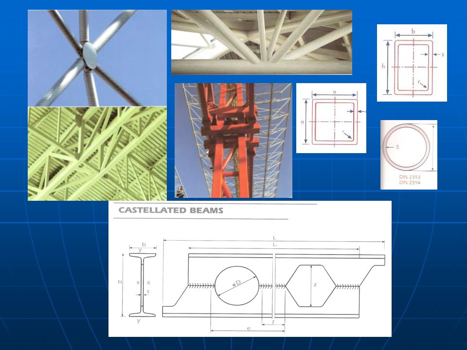
3.3 Sections

26
W – Shape (Wide Flange Beam): Most commonly used for its good strength and easy availability. W-shapes have large moments of inertia around their principal axes, making them ideal for flexure with parallel inner and outer flange surfaces that are of constant thickness. This flange design provides greater strength than that of S shape. S – Shape (American Standard I- Beam): S-shape was the first beam section rolled in America but no longer widely used in building construction. It is a rolled section with two parallel, narrow flanges whose inner surfaces are sloped approximately 17 degrees connected by a web. It is used in monorails and crane runways. HP – Shape: This is similar to W-shape. But it is having width of web and flange equal but thicker than that of W-shape. Due to it’s higher strength, it is used only for withstanding the high impacts of a pile hammer.
: S-shape was the first beam section rolled in America but no longer widely used in building construction. It is a rolled section with two parallel, narrow flanges whose inner surfaces are sloped approximately 17 degrees connected by a web. It is used in monorails and crane runways. HP – Shape: This is similar to W-shape. But it is having width of web and flange equal but thicker than that of W-shape. Due to it’s higher strength, it is used only for withstanding the high impacts of a pile hammer.")
27
C – Channel: Similar to S-shape, C shape has two narrow, tapering, parallel flanges except that it extends only on one side of the web. It is not effective as a beam or column. However, it is best to use for framing floor openings, stringers for steel stairs and stairwells. Efficient built-up members can be constructed out of channel assembled together with other structural shapes and connected by bolts or welds. The profiles of C-shapes available from different manufacturers are essentially the same. M – Shape: M-shapes are similar to W-shapes in cross sectional profile. These shapes are lightweight and cannot be classified as W, S, or HP shapes. MC – Channel: It is very similar to channel but differs with the width and slope of it’s flange. MC-shapes are special purpose channel other than the standard C-shapes. The availability of these shapes is limited and should be Prof. checked prior to specifying their use.

28
L – Angle: It’s legs may be equal or unequal and it is used for bracings, connections and trusses.
WT – Shape: These shapes are manufactured directly from W, M, and S-shapes split longitudinally at mid-depth. However, these can also be produced by off-centre splitting as specified on order to the manufacturer. Structural tees are often used as top and bottom chords of pre-fabricated trusses and sometimes as lintels. Pipe: Steel pipe is also used as a structural member, specifically as column, in building construction. It has three classifications- the standard weight, extra strong, and double-extra strong. Its high strength-to-weight ratios give it excellent load bearing capabilities. It has also uniform wall thickness and exceptional concentricity simplifying fabrication and reducing material costs. It is used for handrails, columns and bollards.

29
HSS (Hollow Structural Shape): Earlier, it was referred as tubular section. Hollow Structural Section is high strength welded steel tubing used as structural elements in buildings and other structures and a variety of manufactured products. It is produced in round, square and rectangular shapes and a broad range of sizes. Benefits include aesthetic appeal, high strength to-weight ratios, uniform strength, cost effectiveness and recycling. PL and FL Bars: They are having a thickness greater than 1/8”. They are used as base plate, cap plate, shear plate and end plate connections. Sheet Metal: Thickness less than 1/8” and is mostly not under the scope of a steel fabricator. It is referred as gage material. Metal Deck: Steel deck is made by cold forming structural grade sheet steel into a repeating pattern of parallel ribs. Standard deck width varies with the product used but full sheets are usually 12", 18", 24", 30" or 36". Deck is typically attached to the building frame with arc puddle welds, self drilling screws or powder or pneumatically driven pins. Sheet to sheet fastening is done with screws, button punching (crimping), or welds.
, or welds.")
35
Prof. Dr. Nesrin YARDIMCI

37
3.4 Constructability It needs four processes to make a complete steel structure: Production, Detailing, Fabrication, Erection Production & Recycling Generally, high quality steel can be produced from steel scraps within 3 hours. These scraps are put in a furnace with carbon electrodes. Then, the molten metal is poured into the container of required shape. The properties of steel are varied by its carbon content because it is the major composition of steel with iron. As per the requirements, Mn, Ni and Cr also are added to make changes the properties of steel. The unshaped steel pieces are in the form of flats, billets, ingots and near net shapes before getting required structural member.

38
Detailing It is the process to create drawings and giving so precise and accurate dimensions to them which help much for complete fabrication and erection of steel structures. Fabrication This is to be done in workshop with the help of detailed shop drawings. Generally, the required holes in a steel member are drilled at one go. The other processes like welding, punching and bending, etc. also are done in workshop. Finally, the parts are assembled according to the assembly drawings and they are marked with separate assembly number. Erection After fabrication, the marked assemblies are taken to working site by transport. It is a difficult process compared to detailing and fabrication. The detailed drawings should be more comfortable to erection labours working and safety wise.

39
4. PROPERTIES OF STEEL BUILDINGS
Rapid construction in all weathers Ease of fabrication and speed of erection Easy field repair Design flexibility Renewable Components can be re-used Dimensional stability Repairing and strengthening Restoration and renovation Reduced form and scaffold Structure can start to function right after its completion Quality and comfort Prof. Dr. Nesrin YARDIMCI

40
4.1 Architectural Steel creates architectural creativity and diversity.

41
Reduced number of columns. Smaller beam and column sections.
Thin slabs. Prof. Dr. Nesrin YARDIMCI

42
Space for installation.

43
Space : Clear spans achieved by using steel reduced number of supports, thereby increasing useable space, leading to increase flexibility of use of the enclosed space Comfort: The use of insulating materials improves acoustic, thermal and vibration comfort to acceptable or better levels, making the internal environment more peaceful and pleasant, bathing it in natural light coming through wide openings from outside. Aesthetics: Slender, elegant steel structures fit harmoniously into every kind of rural and urban environment. Steel structures are often used to renovate old buildings and can be adopted to both classical and contemporary styles. Flexibility: Steel solutions such as those used in office space with spans 18 meters, make it possible to rearrange the space to suit changes in use and thus support changing lifestyles and accommodate the any changes that lie ahead. Freedom: Opening up spaces, steel gives free rein to creativity. Because of its mechanical properties steel can accommodate any architectural design. It offers virtually infinite opportunities with respect to shape, colour and appearance. Creativity: Steel encourages architectural creativity and diversity. Though its ability to meet the highest technical standards while imposing few constrains with respect to shape, steel has given rise to an explosion in inventiveness. Quality and comfort: Because its structures have optimum weight/strength ratio steel opens up optimum, luminous space. Premises can be modified or enlarged to adapt to new uses or lifestyles and to improve the quality of life and comfort. The small amount of work required on site improves safety and convenience during the project.

44
4.2 Earthquake Steel structural systems are advantageous in earthquake areas.
Steel systems have low self-weigh. So earthquake load is less than the other systems (F=m*a). The ability to absorb energy is in large amounts. Plastic hinges may occur and this gives more safety in design. 450 345
. The ability to absorb energy is in large amounts. Plastic hinges may occur and this gives more safety in design")
45
4.3 Recycling Steel is 100% recyclable.
100% of the steel used in construction (all products) are recyclable. More over 80% of these steel have now themselves been produced from recycled steel. They conserve the planet’s natural sources during construction by limiting the need for such materials as water and aggregates. Additionally, steel structures can be partly or completely dismantled and reused.
 are recyclable. More over 80% of these steel have now themselves been produced from recycled steel. They conserve the planet’s natural sources during construction by limiting the need for such materials as water and aggregates. Additionally, steel structures can be partly or completely dismantled and reused.")
46
4.4 Quality Structural steel is an industrial product.
All parts of the structural system are built in a factory environment, according to standards and regulations and they have industrial quality guarantee. All structural steel materials can be seen and control, during the construction of the building and after it is built and used. This means transparency in every state of production and construction.

47
4.5 Environment To built in steel is to respect the environment.
Steel construction may be recycled indefinitely. Sections are produced exclusively from steel scrap. Use natural recourses and energy in a rational way. It is possible to construct buildings in very small construction sites. Work site is clean and does not generate dust and waste. The amount of work on site is limited and requires less transport Does not harm the environment in any stage of the construction. (Dry methods.)
")
48
4.6 Sustainability Less weight Small cross-sections
Transparent facades Flexibility in design Easily modification or enlarging Re-use Recycling

49
4.7 Reconstruction without destruction
When steel buildings no longer have a reason for existence at the place in which they are located, they can be dismantled and rebuilt elsewhere. This solution has proved itself for buildings and car parks intended as temporary remedies to problems posed by current requirements. So steel is reused in an optimum manner, and the costs of dismantling and reconstruction are generally less than those of a new construction.

50
4.8 Cost All the factors affecting total cost has to be taken into consideration.
Steel saves time. Prefabrication cuts construction time and allows accurate sequencing of the various building trades. Faster construction means reduced financing costs and leads to earlier rent income. The mechanical properties of steel make it both sturdy and lightweight, so smaller foundations are needed and structures can be built on soils with limited bearing capacity. Longer spans and large volumes can be achieved. Structural system elements are small this means more space to use. Re-use, recycling. Decrease in form and scaffold costs.

51
Economical design of steel members
The labor cost of structural steel run close to 60 percent and material cost close to 25 percent of total cost. Economical steel structures are the following: Open communications between all involved in a particular project. Information from the steel companies and steel warehousers about the sizes and lengths of sections available. To smooth out the sizes by selecting many members of the same sizes although some of them may be slightly overdesigned. The cost of erection and fabrication are approximately the same for light and heavy members (beams should be spaced as far apart as possible). Should be painted only if so required by the applicable specification.
. Should be painted only if so required by the applicable specification.")
52
Repeating the same section will reduce the detailing, fabrication and erection costs.
For larger sections (particularly the built-up ones) the designer needs to have information about transportation problems. Sections should be selected that are reasonably easy to erect and which have no conditions that will make them difficult to maintain (bridge members may be periodically painted). Every effort should be made to select steel members that will fit in with the requirements of filling (pipes, ducts, conduits) of the building. Economy can be realized when fabrication is minimized.
 the designer needs to have information about transportation problems. Sections should be selected that are reasonably easy to erect and which have no conditions that will make them difficult to maintain (bridge members may be periodically painted). Every effort should be made to select steel members that will fit in with the requirements of filling (pipes, ducts, conduits) of the building. Economy can be realized when fabrication is minimized.")
53
Cost Reinforced concrete Structural steel Span or Number of floor m

54
Column cross-sections
1000 kN, 3.6 m buckling length, 25 mm fire proof 170 120x120 235 MPa 140x140 190 HEB180 HEA180 355 MPa 290 B 45 230 221 kN, 3.6 m buckling length, 25 mm fire proof 850 400 B 45 350x350 355 MPa 300 250x250 HD400x382 466 HD400x287 460 MPa 443

55
4.9 With other materials Visible or invisible, steel is paired with many other materials in construction. It facilitates suitable combinations to enable both materials to be used to best effect. Steel and concrete Composite construction makes the most of characteristics and advantages of both materials (floors, bridges and engineering structures). Composite construction achieves the best trade-off between mechanical performance, weight saving, aesthetics and cost. Steel and glass In conjunction with glass, steel is light and transparent. Spectacular state-of-the-art solutions are possible (skylights, atriums, glass facades). Glass allows natural lighting so the combination saves energy. Steel and wood Within the dry construction sector, steel is a natural partner for wood in all assembly functions (structure, facades, interior finishing, etc.), with warm, aesthetic and comfortable results.
. Composite construction achieves the best trade-off between mechanical performance, weight saving, aesthetics and cost. Steel and glass. In conjunction with glass, steel is light and transparent. Spectacular state-of-the-art solutions are possible (skylights, atriums, glass facades). Glass allows natural lighting so the combination saves energy. Steel and wood. Within the dry construction sector, steel is a natural partner for wood in all assembly functions (structure, facades, interior finishing, etc.), with warm, aesthetic and comfortable results.")
57
4.10 Fireproofing Although structural members are incombustible, their strength is tremendously reduced at temperatures commonly reached in fires. Furthermore steel is an excellent heat conductor non-fireproofed steel members may transmit enough heat from burning section or compartment of a building to ignite materials with which they are in contact in adjoining sections of the building. When steel is used in combination with other acceptable materials such as concrete and plaster, building code fire resistance requirements can be met or exceeded. And the building may have to include a sprinkler system. Fire safety analysis.

58
Active systems: Fire detection systems, sprinkler systems Passive systems will be more the part of the engineer. An engineer can design the structure in such a way that it will achieve to resist in case of fire. (Can do some partitioning in the building; fire resistance analysis)
")
59
The fire resistance is just express of a period of time.
For the steel section we define a section factor for the section, this is the surface divided by the volume.

61
The first thing is to take that into account in the design that means you didn’t have to protect the steel.

62
To put just a sort of plaster around the beams (low or high density).
.")
63
The cheapest one. Using the spray fire protection like vermiculite in front of the beam after the steel structure is erected.

64
Tubular column, with water in it on top of the building, There is tanks like a swimming pool and when there is a fire the column heats so hot water goes up to the pool, and it cools down and it goes down again. (A natural circulation of the water in the building.)
.")
67
4.11 Corrosion Most steels are susceptible to corrosion when freely exposed to air and water, and therefore must be painted periodically. Prof. Dr. Nesrin YARDIMCI

68
4.12 Buckling 4.13 Fatigue 4.14 Brittle fracture
As the length and slenderness of a compression member is increased, its danger of buckling increases. 4.13 Fatigue If steel is subjected to a large number of stress reversals or even to a large number of variations of tensile stress its strength may be reduced. 4.14 Brittle fracture Under certain conditions steel may loose its ductility and brittle fracture may occur at places of stress concentrations. (Fatigue type of loadings; very low temperatures; three axial stress conditions.)
")
69
5. STEEL STRUCTURAL SYSTEMS
Structures may be divided into three general categoris Framed structures Most typical buildings Shell Type Structures Tanks Suspension Type Structures Bridges, roofs

70
It is advantageous to use steel structural systems
in the following type of buildings Buildings on poor soil conditions Buildings in earthquake regions Multi storey and high rise buildings Industrial buildings Bridges Car parks Temporary buildings Rapid constructions Restoration and renovation constructions Repair and retrofitting

71
6. SPECIFICATIONS AND LOADS
The design of most structures is controlled by building codes and specifications. Governments establish building codes which are actually laws or ordinances and vary from country to country. Codes specify design loads, design stresses, construction type, material quality and other factors. IBC: International Building Code; EC: Euro Codes; EN: Euro Norms; BS: British Standards; DIN: Germen Norms Organizations publish recommended practices for regional or national use and their specifications are not legally enforceable. AISI: American Iron and Steel Institute AISC: American Institute of Steel Construction AASHTO: America Association of State Highway and Transportation Officials Turkish Specifications and Building Codes for Steel Structures TS 498 : Design Loads for Buildings TS 648 : Building Code for Steel Structures TS 3357 : Building Code for the Design and Execution of Welded Connections in Steel Structures Turkish Earthquake Code-2007

72
6.1 Loads Loads are classified according to their character and duration of application. (Dead Loads, Live Loads, Environmental Loads.) Dead Loads: Loads of constant magnitude that remain in one position (Structural frames own weight and other loads that are permanently attached to the frame). Live Loads: Loads that may be change in position and magnitude. Floor loads, Traffic loads for bridges, Impact loads, Longitudinal loads, Soil pressure, Hydrostatic pressure, Thermal force, Centrifugal force. Environmental Loads: Snow load, Rain load, Wind load, Earthquake load. These loads are referred to as service or working loads. Various combinations of these loads that feasibly occur at the same time are grouped together.
. Live Loads: Loads that may be change in position and magnitude. Floor loads, Traffic loads for bridges, Impact loads, Longitudinal loads, Soil pressure, Hydrostatic pressure, Thermal force, Centrifugal force. Environmental Loads: Snow load, Rain load, Wind load, Earthquake load. These loads are referred to as service or working loads. Various combinations of these loads that feasibly occur at the same time are grouped together.")
73
Dead loads: Self-weight of the structure; weight of non-structural components; referred as gravity loads. Live loads are not permanent; can be act any time; locations may not be fixed. Static load: If a load is applied slowly and is not removed and applied an excessive number of times. Impact load: If the load is applied suddenly and is not removed (like moving crane). Fatigue: If the load applied and removed many times over the life of the structure. Wind load: Exerts pressure or suction on the exterior surfaces and it has a transient nature; is usually considered a separate category. Earthquake load: A special category. Snow load: A separate category.
. Fatigue: If the load applied and removed many times over the life of the structure. Wind load: Exerts pressure or suction on the exterior surfaces and it has a transient nature; is usually considered a separate category. Earthquake load: A special category. Snow load: A separate category.")
74
6.2 Design philosophies Adequate safety no matter what design philosophie is used. Provision must be made for both overload and understrength. The fundamental requirement is: Required strength ≤ Available strength Limit states: Conditions of a structure at which it ceases to fulfill its intended function Ultimate limit state (Safety) Equilibrium, yield, rupture, large deformations, mecanism, buckling, local buckling, warping, fatigue, overturning, plastic strength and sliding. Serviceability limit state (Concerned with occupancy of building) Deflection, vibration, permanent deformation and cracks.
 Equilibrium, yield, rupture, large deformations, mecanism, buckling, local buckling, warping, fatigue, overturning, plastic strength and sliding. Serviceability limit state (Concerned with occupancy of building) Deflection, vibration, permanent deformation and cracks.")
75
Allowable Strength Design (ASD) Required strength ≤ Allowable strength Allowable strength = Nominal strength / Safety factor Allowable Stress Design (ASD) (In the elastic range) Maximum applied stress ≤ Allowable stress Plastic Design (Failure conditions rather than working load conditions) Working loads are multiply by the load factor to obtain the failure loads. Members would reach the point of failure under the factored loads but are safe under working loads Load and Resistance Factor Design (LRFD) Load factors are applied to service loads and theoretical strength of the member is reduced by a resistance factor. Σ(Loads x Load factors) ≤ Resistance x Resistance factor
 Load factors are applied to service loads and theoretical strength of the member is reduced by a resistance factor. Σ(Loads x Load factors) ≤ Resistance x Resistance factor .")
76
6.3.1 Safety factors for ASD Allowable strength design Ra ≤ Rn / Ω
Ra = Required strength Rn = Nominal strength (Calculated theoretical strength with no safety factors or resistance factors.) Ω = Safety factor (>1) Rn / Ω = Allowable strength Yielding or buckling Ω=1.67 Rupture Ω=2.00 Allowable stress design f ≤ F f=Applied stress F= Allowable stress
 Ω = Safety factor (>1) Rn / Ω = Allowable strength. Yielding or buckling Ω=1.67. Rupture Ω=2.00. Allowable stress design. f ≤ F. f=Applied stress. F= Allowable stress.")
77
The method of analysis are often subject to errors.
Load factors and safety factors are subject to so many uncertainties: Material strength may vary from their assumed values (creep, corrosion, fatigue). The method of analysis are often subject to errors. Hurricanes, earthquake etc. cause conditions difficult to predict. The stresses produced during fabrication and erection are often severe. They may exceed the stresses occur after the structure is completed. There are technological changes that affect the magnitude of live loads. (Dead loads can usually be estimated quite closely.) Presence of residual stresses and stress concentrations, variation of dimensions of the member cross section and so on.
. The method of analysis are often subject to errors. Hurricanes, earthquake etc. cause conditions difficult to predict. The stresses produced during fabrication and erection are often severe. They may exceed the stresses occur after the structure is completed. There are technological changes that affect the magnitude of live loads. (Dead loads can usually be estimated quite closely.) Presence of residual stresses and stress concentrations, variation of dimensions of the member cross section and so on.")
78
REFERENCES F. Hart, W. Henn, H. Sontag, Multi-storey Buildings in Steel, Editor of English Edition: G. Bernard Godfrey, Granada Publishing, London. Martin L.H., Purkiss J. A., Structural Design of Steelwork, Edward Arnold, Hodder&Stoughton, London. Galambos T.V., Lin F. J., Johnston B. G., Basic Steel Design with LRFD, Prentice-Hall Inc., NJ. Les Carnets De L’Acier, Aout,2003. Deren H., Uzgider E., Piroğlu F., Çelik Yapılar, Çağlayan Kitapevi, Beyoğlu-İstanbul. Coosje van Bruggen, Frank O. Gehry: Guggenheim Museum Bilbao,The Solomon Foundation, New York. Deprem Bölgelerinde Yapılacak Binalar Hakkında Yönetmelik-DBYBHY-2007. William T. Segui Steel Design, Cengage Learning, USA, 4th Edition. Salmon Charles G., Johnson John E., Malhas Faris A., Steel Structures, Harper&Row, Publishers, New York. Jack C. Mc Cormak, Structural Steel Design, Pearson, Prentice Hall, 4th Edition. Spiegel L., Limbrunner G.F., Applied Structural Steel Design, Prentice Hall, 3rd Edition. Thanks to ArcelorMittal Borusan Mannesmann Corus Galvaçelik Rozak Türk Yapısal Çelik Derneği Yapı Endüstri Merkezi

Similar presentations


![>ENTER< [PLS PUT ON SAFETY HELMETS BEFORE ENTERING THIS SITE.]](/8/2437266/big_thumb.jpg ">ENTER< [PLS PUT ON SAFETY HELMETS BEFORE ENTERING THIS SITE.]>")


