Download presentation
Presentation is loading. Please wait.

1
QETA/021 Mechanised Welding Processes 501/1130/9 EAL Level 3 Diploma in Engineering Technology (QCF)
")
2
Session Aims 21.1 Know the principles of mechanised welding processes 21.2 Know the principles of mechanised welding metallurgy 21.3 Know the principles of welding health and safety applied to mechanised welding 21.4 Be able to use mechanised welding equipment 21.5 Be able to use mechanised welding consumables 21.6 Be able to produce welds using mechanised welding procedures

3
21.1 Know the principles of mechanised welding processes You will be able to: Explain electrical/electric arc theory Explain fusion arc welding principles Demonstrate knowledge and understanding of specific principles applicable to mechanised welding Critically compare the types of welds and joints

4
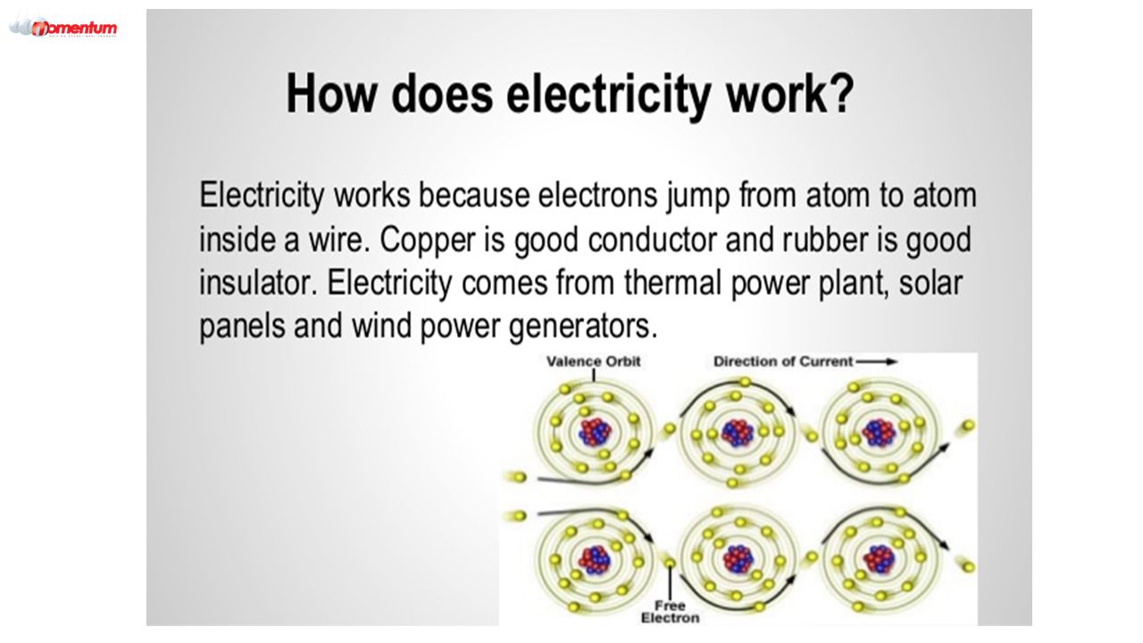
The Nature of Electricity (the Flow of Electrons) Electron flow is what we think of as electrical current. We are familiar with two types of electron flow, Direct Current, or DC, and Alternating Current, or AC. Direct Current is the kind of electrical flow we get from batteries and solar cells, when electrons travel in only one direction. An electric current is a flow of electric charge. In electric circuits this charge is often carried by moving electrons in a wire. It can also be carried by ions in an electrolyte, or by both ions and electrons such as in a plasma. The SI unit for measuring an electric current is the ampere, which is the flow of electric charge across a surface at the rate of one coulomb per second. Electric current is measured using a device called an ammeter.

5
The Nature of Electricity (the Flow of Electrons) Electric currents cause Joule heating, which creates light in incandescent light bulbs. They also create magnetic fields, which are used in motors, inductors and generators. The particles that carry the charge in an electric current are called charge carriers. In metals, one or more electrons from each atom are loosely bound to the atom, and can move freely about within the metal. These conduction electrons are the charge carriers in metal conductors.

7
AC and DC Current AC and DC If the current flows in only one direction it is called direct current, or DC. Batteries and solar cells supply DC electricity. A typical battery may supply 1.5V. The diagram shows an oscilloscope screen displaying the signal from a DC supply. If the current constantly changes direction it is called alternating current, or AC. Mains electricity is an AC supply. The UK mains supply is about 230V. It has a frequency of 50Hz (50 hertz), which means that it changes direction and back again 50 times a second. The diagram shows an oscilloscope screen displaying the signal from an AC supply.
, which means that it changes direction and back again 50 times a second. The diagram shows an oscilloscope screen displaying the signal from an AC supply..")
8
Sinusoidal Waveform and Polarity Sinusoidal Waveform (or Sine Wave) The sine wave or sinusoid is a mathematical curve that describes a smooth repetitive oscillation. It is named after the function sine, of which it is the graph. It occurs often in pure and applied mathematics, as well as physics, engineering, signal processing and many other fields. The sine wave is important in physics because it retains its wave shape when added to another sine wave of the same frequency and arbitrary phase and magnitude. It is the only periodic waveform that has this property. https://en.wikipedia.org/wiki/File:ComplexSinInATimeAxe.gif

9
Electrical Polarity Electrical polarity (positive and negative) is present in every electrical circuit. Electrons flow from the negative pole to the positive pole. In a direct current (DC) circuit, one pole is always negative, the other pole is always positive and the electrons flow in one direction only.
 circuit, one pole is always negative, the other pole is always positive and the electrons flow in one direction only..")
10
Electrical Polarity

11
Voltage, Current, Resistance, Power and Energy Voltage Voltage, also called electromotive force, is a quantitative expression of the potential difference in charge between two points in an electrical field. The greater the voltage, the greater the flow of electrical current (that is, the quantity of charge carriers that pass a fixed point per unit of time) through a conducting or semiconducting medium for a given resistance to the flow. Voltage is symbolized by an uppercase italic letter V or E. The standard unit is the volt, symbolized by a non-italic uppercase letter V. One volt will drive one coulomb (6.24 x 10 18 ) charge carriers, such as electrons, through a resistance of one ohm in one second.currentcoulomb electronsresistanceohm
 through a conducting or semiconducting medium for a given resistance to the flow. Voltage is symbolized by an uppercase italic letter V or E. The standard unit is the volt, symbolized by a non-italic uppercase letter V. One volt will drive one coulomb (6.24 x ) charge carriers, such as electrons, through a resistance of one ohm in one second.currentcoulomb electronsresistanceohm.")
12
Voltage, Current, Resistance, Power and Energy Current Current is a flow of electrical charge carriers, usually electrons or electron-deficient atoms. The common symbol for current is the uppercase letter I. The standard unit is the ampere, symbolized by A. One ampere of current represents one coulomb of electrical charge (6.24 x 10 18 charge carriers) moving past a specific point in one second. Physicists consider current to flow from relatively positive points to relatively negative points; this is called conventional current or Franklin current. Electrons, the most common charge carriers, are negatively charged. They flow from relatively negative points to relatively positive points.ampere Electric current can be either direct or alternating. Direct current (DC) flows in the same direction at all points in time, although the instantaneous magnitude of the current might vary. In an alternating current (AC), the flow of charge carriers reverses direction periodically. The number of complete AC cycles per second is the frequency, which is measured in hertz. An example of pure DC is the current produced by an electrochemical cell. The output of a power-supply rectifier, prior to filtering, is an example of pulsating DC. The output of common utility outlets is AC.ACfrequencyhertz
 moving past a specific point in one second. Physicists consider current to flow from relatively positive points to relatively negative points; this is called conventional current or Franklin current. Electrons, the most common charge carriers, are negatively charged. They flow from relatively negative points to relatively positive points.ampere Electric current can be either direct or alternating. Direct current (DC) flows in the same direction at all points in time, although the instantaneous magnitude of the current might vary. In an alternating current (AC), the flow of charge carriers reverses direction periodically. The number of complete AC cycles per second is the frequency, which is measured in hertz. An example of pure DC is the current produced by an electrochemical cell. The output of a power-supply rectifier, prior to filtering, is an example of pulsating DC. The output of common utility outlets is AC.ACfrequencyhertz.")
13
Voltage, Current, Resistance, Power and Energy Resistance Resistance is the opposition that a substance offers to the flow of electric current. It is represented by the uppercase letter R. The standard unit of resistance is the ohm, sometimes written out as a word, and sometimes symbolized by the uppercase Greek letter omega.currentohm When an electric current of one ampere passes through a component across which a potential difference (voltage) of one volt exists, then the resistance of that component is one ohm. (For more discussion of the relationship among current, resistance and voltage, see Ohm's law.)amperevoltagevoltOhm's law
 of one volt exists, then the resistance of that component is one ohm. (For more discussion of the relationship among current, resistance and voltage, see Ohm s law.)amperevoltagevoltOhm s law.")
14
Voltage, Current, Resistance, Power and Energy Power Electrical power is the rate at which electrical energy is converted to another form, such as motion, heat, or an electromagnetic field. The common symbol for power is the uppercase letter P. The standard unit is the watt, symbolized by W. In utility circuits, the kilowatt (kW) is often specified instead;1 kW = 1000 W.electromagnetic fieldwatt One watt is the power resulting from an energy dissipation, conversion, or storage process equivalent to one joule per second. When expressed in watts, power is sometimes called wattage. The wattage in a direct current (DC) circuit is equal to the product of the voltage in volts and the current in amperes. This rule also holds for low-frequency alternating current (AC) circuits in which energy is neither stored nor released. At high AC frequencies, in which energy is stored and released (as well as dissipated or converted), the expression for power is more complex.jouleAC
 is often specified instead;1 kW = 1000 W.electromagnetic fieldwatt One watt is the power resulting from an energy dissipation, conversion, or storage process equivalent to one joule per second. When expressed in watts, power is sometimes called wattage. The wattage in a direct current (DC) circuit is equal to the product of the voltage in volts and the current in amperes. This rule also holds for low-frequency alternating current (AC) circuits in which energy is neither stored nor released. At high AC frequencies, in which energy is stored and released (as well as dissipated or converted), the expression for power is more complex.jouleAC.")
15
Voltage, Current, Resistance, Power and Energy Energy Energy causes things to happen around us. Look out the window. During the day, the sun gives out light and heat energy. At night, street lamps use electrical energy to light our way. When a car drives by, it is being powered by gasoline, a type of stored energy. The food we eat contains energy. We use that energy to work and play. The definition of energy in the introduction: "Energy Is the Ability to Do Work." Energy can be found in a number of different forms. It can be chemical energy, electrical energy, heat (thermal energy), light (radiant energy), mechanical energy, and nuclear energy Energy makes everything happen and can be divided into two types: Stored energy is called potential energy. Moving energy is called kinetic energy.
, light (radiant energy), mechanical energy, and nuclear energy Energy makes everything happen and can be divided into two types: Stored energy is called potential energy. Moving energy is called kinetic energy..")
16
Energy is measured in many ways. One of the basic measuring blocks is called a Btu. This stands for British thermal unit and was invented by, of course, the English. Btu is the amount of heat energy it takes to raise the temperature of one pound of water by one degree Fahrenheit, at sea level. One Btu equals about one blue-tip kitchen match. One thousand Btus roughly equals: One average candy bar or 4/5 of a peanut butter and jelly sandwich. It takes about 2,000 Btus to make a pot of coffee. Energy also can be measured in joules. Joules sounds exactly like the word jewels, as in diamonds and emeralds. A thousand joules is equal to a British thermal unit. 1,000 joules = 1 Btu Voltage, Current, Resistance, Power and Energy

17
A piece of buttered toast contains about 315 kilojoules (315,000 joules) of energy. With that energy you could: Jog for 6 minutes Bicycle for 10 minutes Walk briskly for 15 minutes Sleep for 1-1/2 hours Run a car for 7 seconds at 80 kilometres per hour (about 50 miles per hour) Light a 60-watt light bulb for 1-1/2 hours Or lift that sack of sugar from the floor to the counter 21,000 times!
 Light a 60-watt light bulb for 1-1/2 hours Or lift that sack of sugar from the floor to the counter 21,000 times!.")
18
Voltage, Current, Resistance, Power and Energy

19
Nature and characteristics of the Arc (AC & DC) An electric arc or arc discharge is an electrical breakdown of a gas that produces an ongoing plasma discharge, resulting from a current through normally nonconductive media such as air. An arc discharge is characterized by a lower voltage than a glow discharge, and relies on thermionic emission of electrons from the electrodes supporting the arc. An archaic term is voltaic arc, as used in the phrase "voltaic arc lamp".electrical breakdownplasmadischargenonconductiveairglow dischargethermionic emission A drawn arc can be initiated by two electrodes initially in contact and drawn apart; this can initiate an arc without the high-voltage glow discharge. This is the way a welder starts to weld a joint, momentarily touching the welding electrode against the workpiece then withdrawing it till a stable arc is formed. Another example is separation of electrical contacts in switches, relays and circuit breakers; in high-energy circuits arc suppression may be required to prevent damage to contacts.welderarc suppression

20
Industrially, electric arcs are used for welding, plasma cutting, for electrical discharge machining, as an arc lamp in movie projectors and follow spots in stage lighting. Electric arc furnaces are used to produce steel and other substances. Calcium carbide is made in this way as it requires a large amount of energy to promote an endothermic reaction (at temperatures of 2500 °C).weldingplasma cuttingelectrical discharge machiningarc lampmovie projectorsfollow spotsstage lightingElectric arc furnacessteelCalcium carbideendothermicreaction Spark plugs are used in internal combustion engines of vehicles to initiate the combustion of the fuel in a timed fashion. Spark gaps are also used in electric stove lighters (both external and built-in). Nature and characteristics of the Arc (AC & DC)
.weldingplasma cuttingelectrical discharge machiningarc lampmovie projectorsfollow spotsstage lightingElectric arc furnacessteelCalcium carbideendothermicreaction Spark plugs are used in internal combustion engines of vehicles to initiate the combustion of the fuel in a timed fashion. Spark gaps are also used in electric stove lighters (both external and built-in). Nature and characteristics of the Arc (AC & DC).")
21
Arc Power and Energy (Arc Voltage and Heat Input) Arc Voltage It is the voltage that appears across the contacts of the circuit breaker during the arcing period. As soon as the contacts of the circuit breaker separate, an arc is formed. The voltage that appears across the contacts during arcing period is called the arc voltage. Its value is low except for the period the fault current is at or near zero current point. At current zero, the arc voltage rises rapidly to peak value and this peak voltage tends to maintain the current flow in the form of arc. Heat Input Heat input (the present best practice term, as it provides a more relevant way of comparing arc welding processes) considers the effect process efficiency has on the energy that actually reaches the workpiece to form the weld. HI is given by the following relationship to Arc Energy or AE. The heat source of an Arc can get up to 6000 degrees Celsius.
 considers the effect process efficiency has on the energy that actually reaches the workpiece to form the weld. HI is given by the following relationship to Arc Energy or AE. The heat source of an Arc can get up to 6000 degrees Celsius..")
22
Magnetic Arc Blow Magnetic arc blow or "arc wander" is the deflection of welding filler material within an electric arc deposit by a build up of magnetic force surrounding the weld pool. Magnetic arc blow can occur because of: Workpiece connection Joint design Poor fit-up Improper settings Atmospheric conditions Arc blow tends to occur if the material being welded has residual magnetism at a certain level, particularly when the weld root is being made, and the welding current is direct current (DC positive or negative).
..")
23
Magnetic arc blow is popularly attributed to a change in the direction of current as it flows into and through the workpiece. Magnetic arc blow is known to begin at field densities as low as 10 gauss and becomes severe at densities of, equal to or greater than, 40 gauss; it is directional and can be classified as forward or backward moving along the joint, but can occasionally occur to the sides depending on the orientation of the poles to the workpiece. Magnetic arc blow is more common in DC welding than in AC welding. Magnetic Arc Blow

24
Fusion Arc Welding Principles Weld Formation To strike the electric arc, the electrode is brought into contact with the workpiece by a very light touch with the electrode to the base metal then is pulled back slightly. This initiates the arc and thus the melting of the workpiece and the consumable electrode, and causes droplets of the electrode to be passed from the electrode to the weld pool. As the electrode melts, the flux covering disintegrates, giving off shielding gases that protect the weld area from oxygen and other atmospheric gases. In addition, the flux provides molten slag which covers the filler metal as it travels from the electrode to the weld pool. Once part of the weld pool, the slag floats to the surface and protects the weld from contamination as it solidifies. Once hardened, it must be chipped away to reveal the finished weld. As welding progresses and the electrode melts, the welder must periodically stop welding to remove the remaining electrode stub and insert a new electrode into the electrode holder.

25
This activity, combined with chipping away the slag, reduces the amount of time that the welder can spend laying the weld, making SMAW one of the least efficient welding processes. The actual welding technique utilized depends on the electrode, the composition of the workpiece, and the position of the joint being welded. The choice of electrode and welding position also determine the welding speed. Flat welds require the least operator skill, and can be done with electrodes that melt quickly but solidify slowly. This permits higher welding speeds Fusion Arc Welding Principles

26
‘Metal Arc’ An electric current, in the form of either alternating current or direct current from a welding power supply, is used to form an electric arc between the electrode and the metals to be joined. The workpiece and the electrode melts forming the weld pool that cools to form a joint. As the weld is laid, the flux coating of the electrode disintegrates, giving off vapours that serve as a shielding gas and providing a layer of slag, both of which protect the weld area from atmospheric contamination.

27
Function of Electrodes Welding electrodes in arc welding an electrode is used to conduct current through a workpiece to fuse two pieces together. Depending upon the process, the electrode is either consumable, in the case of gas metal arc welding or shielded metal arc welding, or non- consumable, such as in gas tungsten arc welding.

28
Function of Electrodes The choice of electrode depends on a number of factors, including the weld material, welding position and the desired weld properties. The electrode is coated in a metal mixture called flux, which gives off gases as it decomposes to prevent weld contamination, introduces deoxidizers to purify the weld, causes weld-protecting slag to form, improves the arc stability, and provides alloying elements to improve the weld quality. Electrodes can be divided into three groups—those designed to melt quickly are called "fast-fill" electrodes, those designed to solidify quickly are called "fast- freeze" electrodes, and intermediate electrodes go by the name "fill-freeze" or "fast- follow" electrodes. Fast-fill electrodes are designed to melt quickly so that the welding speed can be maximized, while fast-freeze electrodes supply filler metal that solidifies quickly, making welding in a variety of positions possible by preventing the weld pool from shifting significantly before solidifying. The composition of the electrode core is generally similar and sometimes identical to that of the base material. But even though a number of feasible options exist, a slight difference in alloy composition can strongly impact the properties of the resulting weld. This is especially true of alloy steels such as HSLA steels.HSLA steels

29
Likewise, electrodes of compositions similar to those of the base materials are often used for welding nonferrous materials like aluminium and copper. However, sometimes it is desirable to use electrodes with core materials significantly different from the base material. For example, stainless steel electrodes are sometimes used to weld two pieces of carbon steel, and are often utilized to weld stainless steel workpieces with carbon steel workpieces. Function of Electrodes

30
Open Circuit and Arc Voltage The highest voltage is the open circuit voltage of the power source. Once the arc is struck the voltage rapidly falls as the gases in the arc gap become ionised and electrically conductive, the electrode heats up and the size of the arc column increases. The welding current increases as the voltage falls until a point is reached at which time the voltage/current relationship becomes linear and begins to follow Ohms Law. What is important to note from Fig. 1 is that as the arc length changes both the voltage and welding current also change – a longer arc giving higher voltage but with a corresponding drop in welding current and vice versa.

31
ISO Weld Symbols Please refer to the following links: http://www.draftsperson.net/images/6/63/Weld_Symbols.png http://triblab.teipir.gr/files/Welding/Lab/CH3_1_Welding_joint_symbols.pdf Refer to the different types of welded joints such as Butt, Tee, Lap and Corner.

32
Fillet and Butt Weld Characteristics Fillet Weld Characteristics: Leg Length Throat Thickness Penetration Number of Runs Surface Finish Weld Toes and Weld Profile Butt Weld Characteristics: Types of Preparation Number of Runs Excess weld metal Penetration Surface Finish

33
Understand the following terms: (1) Manual Welding – This is the type of welding you are most familiar with, what you are doing on MIG/TIG/MMA. Mechanised Welding – This is where adjustment during welding is possible. Automatic Welding – This is where welding is carried out automatically and adjustment is not possible. Semi-Automatic Welding – This is where the automation may stop to allow an adjustment to be made before continuing. Automation – This is where a weld is carried out automatically without the need for set up. Robotic Welding – Welding carried out by a robot instead of a human operator.

34
Understand the following terms: (2) Adaptive Control – uses unique hardware and software to precisely adjust welding parameters, in real time, so every weld is performed within the tightest quality tolerances. Joint Recognition – This is a system of recognising joints so that the automated system recognises what the settings need to be.

35
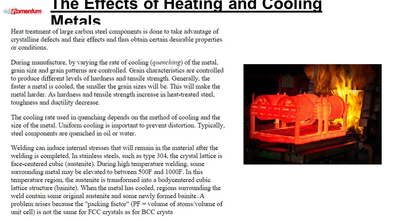
The Effects of Heating and Cooling Metals Heating Metals and Colling slowly and rapidly Heat treating is a group of industrial and metalworking processes used to alter the physical, and sometimes chemical, properties of a material. The most common application is metallurgical. Heat treatments are also used in the manufacture of many other materials, such as glass. Heat treatment involves the use of heating or chilling, normally to extreme temperatures, to achieve a desired result such as hardening or softening of a material. Heat treatment techniques include annealing, case hardening, precipitation strengthening, tempering, normalizing and quenching. It is noteworthy that while the term heat treatment applies only to processes where the heating and cooling are done for the specific purpose of altering properties intentionally, heating and cooling often occur incidentally during other manufacturing processes such as hot forming or welding.industrialmetalworking processesphysicalchemicalmetallurgicalglassannealingcase hardeningprecipitation strengthening temperingquenching With the exception of stress-relieving, tempering, and aging, most heat treatments begin by heating an alloy beyond the upper transformation temperature. This temperature is referred to as an "arrest" because, at the upper transformation temperature nothing happens. Therefore, the alloy must be heated above the temperature for a transformation to occur. The alloy will usually be held at this temperature long enough for the heat to completely penetrate the alloy, thereby bringing it into a complete solid solution.

36
Because a smaller grain size usually enhances mechanical properties, such as toughness, shear strength and tensile strength, these metals are often heated to a temperature that is just above the upper critical temperature, in order to prevent the grains of solution from growing too large. For instance, when steel is heated above the upper critical temperature, small grains of austenite form. These grow larger as temperature is increased. When cooled very quickly, during a martensite transformation, the austenite grain-size directly affects the martensitic grain-size. Larger grains have large grain-boundaries, which serve as weak spots in the structure. The grain size is usually controlled to reduce the probability of breakage.toughnessshear strengthtensile strength The diffusion transformation is very time-dependent. Cooling a metal will usually suppress the precipitation to a much lower temperature. Austenite, for example, usually only exists above the upper critical temperature. However, if the austenite is cooled quickly enough, the transformation may be suppressed for hundreds of degrees below the lower critical temperature. Such austenite is highly unstable and, if given enough time, will precipitate into various microstructures of ferrite and cementite. The cooling rate can be used to control the rate of grain growth or can even be used to produce partially martensitic microstructures. However, the martensite transformation is time-independent. If the alloy is cooled to the martensite transformation (M s ) temperature before other microstructures can fully form, the transformation will usually occur at just under the speed of sound The Effects of Heating and Cooling Metals
 temperature before other microstructures can fully form, the transformation will usually occur at just under the speed of sound The Effects of Heating and Cooling Metals.")
38
Microstructures of Welded Joints Unlike in casting, during welding, where the molten pool is moved through the material, the growth rate and temperature gradient vary considerably across the weld pool. Geometrical analyses have been developed that relate welding speed to the actual growth rates of the solid at various locations in the weld pool. Along the fusion line the growth rate is low while the temperature gradient is steepest. As the weld centre line is approached, the growth rate increases while the temperature gradient decreases. Consequently, the microstructure that develops varies noticeably from the edge to the centre line of the weld. Most of these microstructural features can be interpreted by considering classical theories of nucleation and growth.

39
In welds, weld pool solidification often occurs without a nucleation barrier. Therefore, no significant undercooling of the liquid is required for nucleation of the solid. Solidification occurs spontaneously by linear growth on the partially melted grains. This is the case during autogenous welding. In certain welds, where filler metals are used, inoculants and other grain-refining techniques are used in much the same way as they are in casting practices. In addition, dynamic methods for promoting nucleation such as weld-pool stirring and arc oscillation have been used to refine the weld metal solidification structure. Although the mechanisms of nucleation in weld metal are reasonably well understood, not much attention is given to modelling this phenomenon. Often, weld solidification models assume epitaxial growth and for most of the cases the assumption seems to be appropriate. However, to describe the effects of inoculants, arc oscillations, and weld pool stirring, heat and mass transfer models have to be coupled with either probabilistic models such as cellular automata or deterministic models using the fundamental equations of nucleation as described elsewhere Microstructures of Welded Joints

40
Microstructures and the Changes produced by welding During growth of the solid in the weld pool, the shape of the solid-liquid interface controls the development of microstructural features. The nature and the stability of the solid-liquid interface is mostly determined by the thermal and constitutional conditions (constitutional supercooling) that exist in the immediate vicinity of the interface. Depending on these conditions, the interface growth may occur by planar, cellular, or dendritic growth. Dendritic growth of the solid, with its multiple branches, is shown in Figure 3. Another example of changes in solidification morphology directly related to welding conditions is shown in Figure 4. This figure shows a spot weld on a nickel-based superalloy in which the morphology changes from cellular to dendritic as the growth velocity increases toward the centre of the spot weld after the spot weld arc is extinguished. The micrograph also shows the elimination of a poorly aligned dendriteFigure 3Figure 4
 that exist in the immediate vicinity of the interface. Depending on these conditions, the interface growth may occur by planar, cellular, or dendritic growth. Dendritic growth of the solid, with its multiple branches, is shown in Figure 3. Another example of changes in solidification morphology directly related to welding conditions is shown in Figure 4. This figure shows a spot weld on a nickel-based superalloy in which the morphology changes from cellular to dendritic as the growth velocity increases toward the centre of the spot weld after the spot weld arc is extinguished. The micrograph also shows the elimination of a poorly aligned dendriteFigure 3Figure 4.")
41
Microstructures and the Changes produced by welding

42
Cracking in Welding Definition - What does Cold Cracking mean? Cold cracking is cracking that occurs as the result of hydrogen dissolving in the weld metal and then diffusing into the heat affected zone (HAZ). Cold cracks mostly develop long after the weld metal solidifies, but sometimes appear sooner. Cold weld cracking occurs at temperatures well below 600°F. It is considered a serious welding defect because it can significantly affect the integrity of infrastructure. Cold cracking is also known as hydrogen-induced cracking, delayed cracking or underbead cracking.
. Cold cracks mostly develop long after the weld metal solidifies, but sometimes appear sooner. Cold weld cracking occurs at temperatures well below 600°F. It is considered a serious welding defect because it can significantly affect the integrity of infrastructure. Cold cracking is also known as hydrogen-induced cracking, delayed cracking or underbead cracking..")
43
What exactly is Cold Cracking?? Cold cracking is especially common in thick materials, as they tend to create areas of high restraint and can serve as a heat sink that leads to fast cooling rates. Rapid cooling causes the microstructure in the HAZ to form a new crystalline microstructure called martensite, which very hard, very brittle and lacks ductility. Martensite provides a location for diffusible hydrogen to gather, which causes residual stresses to build in the HAZ. Once these residual stresses reach a critical level, cold cracking occurs. Cold cracking may occur for the following reasons: There is hydrogen in the weld material or atmosphere Susceptible microstructure (martensite) Mechanical stresses (thermal or residual stresses) The following can be done to prevent cold cracking of a metal: Pre-heating the base material in order to reduce the speed of cooling, preventing the formation of martensite on the weld and allowing the hydrogen to be removed from the weld Reducing tension concentration, avoiding discontinuities on the weld or carefully selecting the disposition of the welds and the assembly sequence of the structure Using welding consumables with low hydrogen to minimize the hydrogen diffusion on the weld Selecting the appropriate welding process Cracking in Welding
 Mechanical stresses (thermal or residual stresses) The following can be done to prevent cold cracking of a metal: Pre-heating the base material in order to reduce the speed of cooling, preventing the formation of martensite on the weld and allowing the hydrogen to be removed from the weld Reducing tension concentration, avoiding discontinuities on the weld or carefully selecting the disposition of the welds and the assembly sequence of the structure Using welding consumables with low hydrogen to minimize the hydrogen diffusion on the weld Selecting the appropriate welding process Cracking in Welding.")
44
How Hydrogen appears in Cold Cracking Weld metal hydrogen content The principal source of hydrogen is moisture contained in the flux, this is particularly important in Flux Cored welding, the flux in cored wires and the flux used in submerged arc welding. The amount of hydrogen generated is influenced by the electrode type (where applicable). It is important to note that there can be other significant sources of hydrogen, e.g. from the material, where processing or service history has left the steel with a significant level of hydrogen or moisture from the atmosphere. Hydrogen may also be derived from the surface of the material or the consumable. Sources of hydrogen will include: oil, grease and dirt rust paint and coatings cleaning fluids
. It is important to note that there can be other significant sources of hydrogen, e.g. from the material, where processing or service history has left the steel with a significant level of hydrogen or moisture from the atmosphere. Hydrogen may also be derived from the surface of the material or the consumable. Sources of hydrogen will include: oil, grease and dirt rust paint and coatings cleaning fluids.")
45
How Hydrogen appears in Cold Cracking

46
Lamellar Tearing As lamellar tearing is associated with a high concentration of elongated inclusions oriented parallel to the surface of the plate, tearing will be transgranular with a stepped appearance. Causes It is generally recognised that there are three conditions which must be satisfied for lamellar tearing to occur: Transverse strain - the shrinkage strains on welding must act in the short direction of the plate ie through the plate thickness Weld orientation - the fusion boundary will be roughly parallel to the plane of the inclusions Material susceptibility - the plate must have poor ductility in the through-thickness direction Thus, the risk of lamellar tearing will be greater if the stresses generated on welding act in the through-thickness direction. The risk will also increase the higher the level of weld metal hydrogen Factors to be considered to reduce the risk of tearing The choice of material, joint design, welding process, consumables, preheating and buttering can all help reduce the risk of tearing.

47
Lamellar Tearing

48
Hot Cracking (1) Solidification cracks can appear in several locations, and orientations, but most commonly are longitudinal centreline cracks (coincident with the intersection of grains growing from opposite sides of the weld), or 'flare' cracks, again longitudinal, but at an angle to the through-thickness direction ( Fig.1). Where there is a central segregate band in the plate, cracking may extend from this position at the fusion boundary ( Fig.2). The cracks in all locations can be buried (Fig.3) or surface- breaking.
. The cracks in all locations can be buried (Fig.3) or surface- breaking..")
49
Hot Cracking (1)
")
50
Hot Cracking (2) Cracking is associated with impurities, particularly sulphur and phosphorus, and is promoted by carbon whereas manganese and silicon can help to reduce the risk. To minimise the risk of cracking, fillers with low carbon and impurity levels and a relatively high manganese content are preferred. As a general rule, for carbon-manganese steels, the total sulphur and phosphorus content should be no greater than 0.06%. Weld metal composition is dominated by the consumable and as the filler is normally cleaner than the metal being welded, cracking is less likely with low dilution processes such as MMA and MIG. Plate composition assumes greater importance in high dilution situations such as when welding the root in butt welds, using an autogenous welding technique like TIG, or a high dilution process such as submerged arc welding.

51
Reheat Cracking Issues If possible, avoid welding steels known to be susceptible to reheat cracking. For example, A 508 Class 2 is known to be particularly susceptible to reheat cracking, whereas cracking associated with welding and cladding in A508 Class 3 is largely unknown. The two steels have similar mechanical properties, but A508 Class 3 has a lower Chromium content and a higher manganese content. Similarly, in the higher strength, creep-resistant steels, an approximate ranking of their crack susceptibility.

52
Thus, in selecting a creep-resistant, chromium molybdenum steel, 0.5Cr 0.5Mo 0.25V steel is known to be susceptible to reheat cracking but the 2.25Cr 1Mo which has a similar creep resistance, is significantly less susceptible. Unfortunately, although some knowledge has been gained on the susceptibility of certain steels, the risk of cracking cannot be reliably predicted from the chemical composition. Various indices, including ΔG1, P SR and Rs, have been used to indicate the susceptibility of steel to reheat cracking. Steels which have a value of ΔG1 of less than 2, P SR less than zero or Rs less than 0.03, are less susceptible to reheat cracking Reheat Cracking Issues

53
Reheat Cracking The welding procedure can be used to minimise the risk of reheat cracking by Producing the maximum refinement of the coarse grain HAZ Limiting the degree of austenite grain growth Eliminating stress concentrations The procedure should aim to refine the coarse grained HAZ by subsequent passes. In butt welds, maximum refinement can be achieved by using a steep- sided joint preparation with a low angle of attack to minimise penetration into the side-wall, ( Fig 2a). In comparison, a larger angle V preparation produces a wider HAZ, limiting the amount of refinement achieved by subsequent passes, ( Fig 2b). Narrow joint preparations, however, are more difficult to weld, due to the increased risk of lack of side-wall fusion.
. In comparison, a larger angle V preparation produces a wider HAZ, limiting the amount of refinement achieved by subsequent passes, ( Fig 2b). Narrow joint preparations, however, are more difficult to weld, due to the increased risk of lack of side-wall fusion..")
54
Reheat Cracking

55
The weld toes of the capping pass are particularly vulnerable, as the coarse grained HAZ may not have been refined by subsequent passes. In susceptible steel, the last pass should never be deposited on the parent material, but always on the weld metal, so that it will refine the HAZ. Grinding the weld toes with the preheat maintained has been successfully used to reduce the risk of cracking in 0.5Cr 0.5Mo 0.25V steels.

56
Thermal Cycle in Welding In the present investigation, thermal simulated specimens were used to investigate the effect of welding cooling time and peak temperature on characteristic fracture toughness and microstructure feature of heat-affected zone (HAZ) for an 800 MPa grade high strength low alloy (HSLA) steel. It is found that the fracture toughness is the best for the simulated coarse-grained HAZ. In addition, the size of prior austenite grain, and the volume fraction of bainitic ferrite and constituent increase with increasing the cooling time. However, the volume fraction of martensite decreases with increasing the cooling time. Remarkable decrease of toughness is observed with increasing the size of austenite grain and the volume fraction.

57
Health and Safety Legislation and Current Regulations applicable to the Welding Process Refer back to your previous notes on from QETA/001 module: Health and Safety at Work Act 1974 Personal Protective Equipment Regulations Control of substances hazardous to health regulations Management of Health and Safety at Work Regulations Reporting of Injuries, diseases and dangerous occurrences regulations (R.I.D.D.O.R) Provision and use of work equipment regulations Noise at Work Regulations
 Provision and use of work equipment regulations Noise at Work Regulations")
58
Personal Protective Equipment (PPE) Personal Protective Equipment (PPE) and the reasons for need: Protection of others from Hazards Hot Materials Sparks Falling Objects Heat Burns Safe Start-up and shutdown procedures
 Personal Protective Equipment (PPE) and the reasons for need: Protection of others from Hazards Hot Materials Sparks Falling Objects Heat Burns Safe Start-up and shutdown procedures")
59
Arc Radiation Arc Radiation and the hazards caused by: Visible Light - Intense visible light or 'blue light', passes through the cornea and lens and can dazzle and, in extreme cases, damage the network of optical nerves in your eye. Infra-Red - is perceptible as heat. The main hazard to the eyes is that prolonged exposure causes a gradual but irreversible opacity of the lens. The infrared radiation emitted by normal welding causes damage only within a short distance from the arc. There is an immediate burning sensation in the skin surrounding the eyes should they be exposed to arc heat. The natural human reaction is to move or cover up to prevent the skin heating, which also reduces eye exposure. Ultra-Violet – UV is generated by all arc processes. Excess exposure causes skin inflammation, and possibly even skin cancer or permanent eye damage. However the main risk amongst welders is for inflammation of the eye, commonly known as 'arc eye' or 'flash‘.

60
Types of Hazards from Fumes during Welding Types of fumes: Particulate - Particulate fume is made up of, discrete, solid particles, As the particles are tiny and most of the fume falls into the 'respirable' size range. Respirable particulate fume can be breathed in, reach the lungs, and stay there. The fume is made up mainly of oxides and silicates from the metals present in the consumable and, to some extent, the parent material being used. Whether the fume is likely to cause damage depends largely on the material, or the concentration of it and the length of exposure to it.

61
Gaseous - consists of either one or more pollutant gases, mixed around the welding area. In its gaseous state it can easily enter the lungs. Whether the fume causes damage, depends on what the gas is, and the concentration consumed and the length of time you are exposed to it. Fumes may be formed by welding, or the radiation from it, or the air surrounding the arc, something within the flux or coatings or contaminants on the component. Gaseous fumes are not emitted by the metal or the consumable. Types of Hazards from Fumes during Welding

62
Fume Gases - The fume given off by welding and hot cutting processes is a varying mixture of airborne gases and very fine particles which if inhaled can cause ill health. Gases that may be present in welding and cutting fume are: nitrous oxide (NOx), carbon dioxide (CO2), carbon monoxide (CO) shielding gas (eg Argon, helium) ozone (O3) Types of Hazards from Fumes during Welding
, carbon dioxide (CO2), carbon monoxide (CO) shielding gas (eg Argon, helium) ozone (O3) Types of Hazards from Fumes during Welding.")
63
The visible part of the fume cloud is mainly particles of metal, metal oxide and flux (if used). The exact level of risk from the fume will depend on 3 factors: How toxic the fume is How concentrated the fume is How long you are breathing the fume Types of Hazards from Fumes during Welding

64
Health Effects of Welding Fumes How toxic is the fume? For arc welding, the visible fume comes mostly from the filler wire when it’s exposed to the electric arc. The amount of hazardous substances in the filler wire should be included in the product information that is printed on the original packaging. Many of the common metals used in filler wires are harmful and several have Workplace Exposure Limits (WEL). Cadmium and Beryllium are rarely found, but are particularly toxic. Chromium, Nickel, Vanadium, Manganese and Iron all have WEL’s. Generally the smaller the number for the WEL the more toxic the substance is. The toxic constituents of fume can be affected by the choice of welding process. A full list can be found at: http://www.hse.gov.uk/pubns/priced/eh40.pdfhttp://www.hse.gov.uk/pubns/priced/eh40.pdf
. Cadmium and Beryllium are rarely found, but are particularly toxic. Chromium, Nickel, Vanadium, Manganese and Iron all have WEL’s. Generally the smaller the number for the WEL the more toxic the substance is. The toxic constituents of fume can be affected by the choice of welding process. A full list can be found at:")
65
Methods of Fume/Gas Control Extraction Local Extraction Air Fed Heat Shield (Yellow) Respirator (Red) Breathing Apparatus
 Respirator (Red) Breathing Apparatus")
66
Working in Confined Space A Confined Space: is a place which is substantially enclosed (though not always entirely), and where serious injury can occur from hazardous substances or conditions within the space or nearby (e.g. lack of oxygen). Asphyxiation Hazard Risk of Explosion Risks from Oxygen Enrichment - atmospheric gases are non-toxic but alterations in their concentrations - especially that of oxygen - have an effect upon life and combustion processes. Hazards to Health from Pollutants
. Asphyxiation Hazard Risk of Explosion Risks from Oxygen Enrichment - atmospheric gases are non-toxic but alterations in their concentrations - especially that of oxygen - have an effect upon life and combustion processes. Hazards to Health from Pollutants.")
67
Hazards from fire and safe working procedures adopted You will need to understand: Flammable Materials Suitable types of extinguishers Identification of fire exit and evacuation procedures Refer to the previous material from QETA001

68
Electrical Hazards Electrical hazards associated with welding plant and safe working procedures adopted: Fire Electric Shock Emergency procedures in the event of an electric shock Uses of fuses Electrical insulation Use of earthing Workpiece (welding) Plant Use of circuit breakers (including earth leakage circuit breakers – eclb) Use of no-load low voltage protection devices
 Plant Use of circuit breakers (including earth leakage circuit breakers – eclb) Use of no-load low voltage protection devices")
69
Health and Safety for Welding Health and safety issues associated with welding related activities: Grinding and material removal Safe disposal of waste Workshop layout such as: 1.Obstacles in the workshop 2.Noise or heavy noise areas (muffling or distancing?) 3.Hot Metal fragments or workpieces & safe places to put them 4.Positioning of cables including welding torch leads & electrical and gas cables/hoses
 3.Hot Metal fragments or workpieces & safe places to put them 4.Positioning of cables including welding torch leads & electrical and gas cables/hoses")
70
Moving Loads How to move loads: Manual Methods Overhead Cranes Slings and other lifting aids Please refer to the notes from QETA001 on Manual handling and mechanical aids for moving loads.

71
Describe the equipment requirements for the TIG process Types of Power Sources and their application: Transformers - A transformer-style welding power supply converts the moderate voltage and moderate current electricity from the utility mains (typically 230 or 115 VAC) into a high current and low voltage supply, typically between 17 to 45 (open-circuit) volts and 55 to 590 amperes. Transformers/Rectifiers - A rectifier converts the AC into DC on more expensive machines.

72
Inverters - They generally first rectify the AC power to DC; then they switch (invert) the DC power into a stepdown transformer to produce the desired welding voltage or current. The switching frequency is typically 10 kHz or higher. Although the high switching frequency requires sophisticated components and circuits, it drastically reduces the size of the transformer, as the mass of magnetic components that is required for achieving a given power level goes down rapidly as the operating (switching) frequency is increased. The inverter circuitry also provides features such as power control and overload protection. The high frequency inverter-based welding machines are typically more efficient and provide better control of variable functional parameters than non-inverter welding machines Describe the equipment requirements for the TIG process
 frequency is increased. The inverter circuitry also provides features such as power control and overload protection. The high frequency inverter-based welding machines are typically more efficient and provide better control of variable functional parameters than non-inverter welding machines Describe the equipment requirements for the TIG process.")
73
Types of Power Sources and their application: Generators - Welding power supplies may also use generators or alternators to convert mechanical energy into electrical energy. Modern designs are usually driven by an internal combustion engine. The power is converted first into mechanical energy then back into electrical energy to achieve the step-down effect similar to a transformer. Because the output of the generator can be direct current, or even a higher frequency ac current, these older machines can produce DC from AC without any need for rectifiers of any type, or can also be used for implementing formerly-used variations on so-called heliarc (most often now called TIG) welders, where the need for a higher frequency add-on module box is avoided by the alternator simply producing higher frequency ac current directly.
 welders, where the need for a higher frequency add-on module box is avoided by the alternator simply producing higher frequency ac current directly..")
74
Power Source Characteristics Some Power Source Characteristics: Power Source Duty Cycle - A duty cycle is the percentage of one period in which a signal is active. A period is the time it takes for a signal to complete an on-and-off cycle. Drooping Characteristic (Constant Current) – The name given to power supplies, as the slant of the volt-ampere curve is drooping. If the welder maintains a constant arc length, the welding current will remain the same. Should the welder raise or lower the torch height, a new voltage intersection line is obtained. This movement raises or lowers the welding power supply output current. The curve is not straight but drooping when this occurs. Because of this, the machines may also be called "droopers".
 – The name given to power supplies, as the slant of the volt-ampere curve is drooping. If the welder maintains a constant arc length, the welding current will remain the same. Should the welder raise or lower the torch height, a new voltage intersection line is obtained. This movement raises or lowers the welding power supply output current. The curve is not straight but drooping when this occurs. Because of this, the machines may also be called droopers ..")
75
Power Source Characteristics Welding current – The definition of the current that passes through the Arc of a weld whilst welding occurs. Open Circuit Voltage - As the name implies, no current is flowing in the circuit, because the circuit is open. The voltage is impressed upon the circuit, however, so that when the circuit is completed, the current will flow immediately. Arc Voltage - The voltage across a welding arc.

76
Current control methods Principles of different Current control methods: Stepped Reactor - A means of controlling transformer output by selecting the amount of windings to use. Step control is not preferred, because it is not a smooth, continuous control of transformer output. Moving Core - Moving a core inside the reactor. A continuous current variation is possible. The moving core changes the air gap which changes the reactance. Larger the air gap, smaller the impedance and higher the current. Moving Coil - By changing the position of primary or secondary coil the magnetic coupling will change. Lead screw is used to change the position of coils. Current is high when both the coils are near and less if far. Continuous current variations but require regular maintenance. Moving Shunt - Changing the magnetic coupling between primary and secondary by putting a movable magnetic shunt. Continuous current variations but require regular maintenance. Magnetic shunt causes the leakage flux to vary and thereby adjusts the output current.

77
Current control methods Variable Resistance - A minimum variation in welding current is of paramount importance in the production of satisfactory welds, inasmuch as it is one of the three basic factors that enable resistance welds to be made, i.e., current, pressure, and time. Satiable Reactor - By putting a saturable reactor in the secondary circuit. Eliminates moving parts but more expensive. Secondary reactor impedance is controlled by regulating the saturation level of the core electrically. DC control coil is used. If DC current is flowing in the coil the impedance is less, more output current and reverse in the case of lesser DC current. Instrumentation e.g. ammeter, voltmeter – when using a welding transformer, it is possible to attach and ammeter or voltmeter to the circuit so that you can measure the amperage or voltage of the welding.

78
Calibration of equipment aka Validation - is the procedure of proving that the welder is to the operating specification. Before it can be carried out it is necessary to establish the specification. This depends on the design, the specification to which its manufactured or a specification chose by the user. Generally, the manufacturer doesn’t state values, but if the equipment is manufactured to a recognised National, European or International standard, a level of accuracy is defined for current and arc voltage. However, these are the minimum levels of accuracy and are usually insufficient for mechanised welding. Therefore, for more advanced equipment, the manufacturer may produce to a higher specification. Current control methods

79
Output Monitoring - The power source is monitoring the arc and making millisecond changes in order to maintain a stable arc condition. The term “constant” is relative. A CC power source will maintain current at a relatively constant level, regardless of fairly large changes in voltage, while a CV power source will maintain voltage at a relatively constant level, regardless of fairly large changes in current. CC = Constant Current CV = Constant Voltage Current control methods

80
Tractor Drives – it’s a tracked or wheeled device that has an electric motor on it and has a speed setting and a holster for the torch that moves along a track. Application of Tractor Driven Systems – This can be used in MIG, Sub- arc, plasma cutting, oxyacetylene-propane cutting and much more Fixed Welding Stations – an automated system whereby a welder is fixed in place and a job is put into the best welding position for welding prior to use. Turntables – to rotate the joint, mainly used in pipe welding, this allows for one continuous weld without stop starts and without difficult manual welding techniques or torch adjustments to be used. Positioning Equipment – The job is clamped onto a large manipulation device that can rotate a set SWL to any position and provide greater access to the welding site and eliminate the need to do welds in the overhead or vertical position. Mechanisation Methods (1)
.")
81
Mechanised welding - Welding in which the welding parameters are controlled mechanically or electronically and may be manually varied during welding to maintain the required welding position. Automatic welding - Welding in which all of the welding parameters are controlled. Manual adjustments may be made between welding operations but not during welding. Robotic welding - Automatic welding using a robot that can be pre-programmed to different welding paths and fabrication geometries. Types of assisted Welding Methods

82
Turning Rolls – a rolling device which you attach a section of pipe to rotate the job, this can be done manually or on a variable speed motor. Tilting/Rotating Turntables – these solely tilt or rotate the job on a turntable, a more simplified version of positioning equipment. Column and Boom – These are greatly used to long fillet or butt weld large items that may be difficult to be continuously manually welded due to the distance. This allows for one continuous run. Headstock-Tailstock – These are a variable length device that can be adapted to suit the length of the part and rotate the part either manually or on a motorised mechanism. Mechanisation Methods (2)
.")
83
Applications– mainly large fabrications that creates large welds through large deposition welds without having to create multi-runs Advantages and Disadvantages – Advantages: Can create significantly larger welds in 1 pass, faster than manually doing a multi-run weld, Disadvantages: Creates significant distortion, can only mainly be welded in the PA(Flat) position and can do some H/V welding, you have to collect a large granulated flux afterwards and is significantly more expensive than manual welding Equipment Set-up – A specialised welding torch with a hopper at the back to hold air pressure – this is used to pump the flux into the weld Wire Feed Method – Wire is fed in a 4 roll method similar to MIG welding and the wire size is 2.4mm – 3.2mm wire. Types of flux (Fused, Agglomerated, Mixed) – Fused Flux: provides homogeneity it is difficult to add alloy elements and deoxidizers to fused fluxes. Agglomerated Flux: A ceramic binder is used instead of silicon and requires a high temperature which limits the use of deoxidizers. Mixed Flux: This is a mix of fused, bonded and agglomerates that are consolidated together. Because they are bonded together they unfortunately separate during handling or transit. Submerged Arc Welding
 – Fused Flux: provides homogeneity it is difficult to add alloy elements and deoxidizers to fused fluxes. Agglomerated Flux: A ceramic binder is used instead of silicon and requires a high temperature which limits the use of deoxidizers. Mixed Flux: This is a mix of fused, bonded and agglomerates that are consolidated together. Because they are bonded together they unfortunately separate during handling or transit. Submerged Arc Welding.")
84
Applications – This is an adaptation of Submerged arc welding which allows the joining of thick materials in the vertical up position, it is similar to casting Equipment set up– Submerged arc torch that is specially adapted to the vertical up process Wire Feed Method – The wire is fed in from the top and moves as it solidifies. The electrode wire may be tubular or solid cored. Function of the Flux – A layer of flux is layered at the bottom of the joint in order to act as a medium for to conduct electricity and heat. Benefits – Similar to Submerged Arc except with the discretisation of now being able to do it in vertical up position which couldn’t be previously achieved, no need for special edging preparations such as bevelling etc. Limitations – Similar to submerged Arc, special equipment is required and there is very few uses of welding to justify the cost of having the equipment. Consumable guide variation of process – The electrodes can be added to by adding alloying elements or metal powders to alter the types of metal deposition. Multiple wire method– This means that you can use more than one torch head to increase the deposition rate of the metal to fill up the joint quicker to allow for a faster process time for welding. Electroslag

85
Applications – used to help create larger, longer runs without manual welding Advantages and Disadvantages – Advantages: can allow for greater precision versus manual MIG welding and can be manipulated to get greater penetration Disadvantages: may cost additional money to buy the equipment needed to set up the mechanism Equipment Set-up – Regular MIG welding set attached to a mechanism to aid welding, and possibly a special torch to aid in the mechanisation Wire Feed Method – Use of wire reel such as used in manual MIG Welding Types Gas used– Argon, Helium, Argon/Helium, C02, Argon/C02 Mix, Argon/O2/CO2 Mix, Argon/O2 Mix, Helium/Argon/O2/CO2 mix. Mechanised MIG Welding

86
Mechanised TIG Welding Applications – used to help create larger, longer runs without manual welding and is more precise/cleaner if done in a controlled setting Advantages and Disadvantages – Advantages: can allow for greater precision versus manual TIG welding and can be manipulated to get greater penetration Disadvantages: may cost additional money to buy the equipment needed to set up the mechanism Equipment Set-up – Regular TIG welding set attached to a mechanism to aid welding, and possibly a special torch to aid in the mechanisation Wire Feed Method – Use of filler wire, or a small wire spool Types Gas used– Argon, Helium, Argon/Helium Mix, Helium/Argon Mix, Argon/Hydrogen Mix, Nitrogen and Argon/Nitrogen.

87
Mechanised Plasma Arc Welding Applications – used to help create larger, longer runs without manual welding and is more precise/cleaner if done in a controlled setting Advantages and Disadvantages – Advantages: can allow for greater precision versus manual plasma arc welding and can be manipulated to get greater penetration Disadvantages: may cost additional money to buy the equipment needed to set up the mechanism Equipment Set-up – Regular Plasma Arc welding set attached to a mechanism to aid welding, and possibly a special torch to aid in the mechanisation, water cooling mechanism Wire Feed Method – Autogenus, or with Filler Wire Types Gas used– Argon, Helium, Argon/Helium Mix, Helium/Argon Mix, Argon/Hydrogen Mix.

88
Post-weld cleaning – grinding and linishing of the weld to remove burrs and sharp edges as well as spatter (MMA = slag), wire brush, chipping hammer, hammer and chisel (if required), emery cloth and varying grades of sandpaper. This can significantly improve the quality and appearance of your weld and help in the process of applying Non-Destructive Testing Methods/NDT Testing. Pre and Post Welding Operations in terms of…

89
Argon – In TIG its mainly used on Aluminium, Carbon Steel & Stainless Steel. Most widely used. Helium – It is used to create an inert gas shield and prevent oxidation during welding of metals such as aluminium, stainless steel, copper and magnesium alloys. The addition of helium generally increases weld pool fluidity and travel speed. Argon/Helium Mixture – 75% argon/25% helium, is used for nonferrous base when higher heat input and good weld appearance are needed. 50% argon/50% helium, is used for nonferrous metals thinner than 0.75 inch for high-speed mechanized welding. 25% argon/75% helium, is used for mechanized welding of thick aluminium. Reduces weld porosity in copper Shielding Gas Mixtures

90
Argon/Oxygen – Argon/oxygen blends are mostly widely used for conventional and pulsed spray transfer on clean, plain Carbon and Stainless Steel, provide good arc stability and very low levels of spatter and fume. Higher levels of oxygen will also increase puddle fluidity that may make out-of-position welding more difficult. Helium/Argon/Oxygen/Carbon Dioxide Mixtures – Used when trying Short Circuiting spray method, predominantly on stainless and aluminium. Argon/Carbon Dioxide Mixtures – Most commonly used, is called MIG Universal Gas. Create quality finish and less spatter. Shielding Gas Mixtures

91
Carbon Dioxide – Used in MIG originally before Argon gases became widely used, increases penetration in the weld, but loads of excessive spatter. Usually requires a heater and is cheaper than other welding gases. Gas Pressure & Flow Rates – Gas Pressure/Flow Rates regulates the amount of gas diffused into the weld pool to exclude atmospheric gases. Shielding Gas Mixtures

92
Use of de-oxidants and function of copper coating on steel wire – Because steel oxidises after extended contact with oxygen/air a protective layer of copper is put on around the wire to prevent contamination. Protection of bare wires – Bare wires are concealed so that they don’t cause oxidisation or contaminants getting onto the wire such as spatter, paint or oils. Electrode Wire Storage and Handling – Wire needs to be stored in the packaging ideally until it is ready to be put onto the wire feed and should be handled with care to prevent the breakage of the wire reel. Types of cored wire electrodes – There are two types of cored wires, flux cored and solid cored electrode wires. Describe the electrode wire composition and sizes (1)
.")
93
Flux Cored Wire – Flux Cored Electrode Wire is a commonly used site welding electrode wire as the coating of the electrode wire is covered in a flux containing shielding gas so there is no necessity for gas bottles on site. The flux coating can provide different properties to the weld or the electrode wire when the arc strikes the electrode wire. Self/Gas Shielded – These types of shielded wires are commonly used to give off shielding gas when the arc strikes the electrode wire. Describe the electrode wire composition and sizes (2)
.")
94
Types of Weld Defects (1) Cracks/Cracking/Solidification Cracking - A crack may be defined by a fracture which comes from the stresses created on cooling or acting on the structure. It’s the most serious type of imperfection. They reduce the strength of the weld through the reduction in the cross section thickness but also can readily propagate through stress concentration at the tip, especially under impact loading or during service at low temperature. The main cause of cracking is that the weld bead in the final stage of solidification has insufficient strength to withstand the contraction stresses generated as the weld pool solidifies. Factors which increase the risk include: insufficient weld bead size or shape welding under high restraint high impurity content or a relatively large amount of shrinkage on solidification. Joint design can influence the level of residual stresses. Large gaps between component parts will increase the strain on the solidifying weld metal, especially if the depth of penetration is small. Weld beads with a small depth-to-width ratio, such as formed in bridging a large gap with a wide, thin bead, carries increased risk to solidification cracking. The centre of the weld which is the last part to solidify, is a narrow zone with negligible cracking resistance.

95
Weld Cavities - are a naturally occurring phenomenon found in arc welding. While they can occur with all arc welding processes, they are more prevalent with processes that are capable of higher deposition rates and producing larger weld puddles (i.e.. welds with a greater volume of liquid metal). In addition, they are more pronounced when welding with a vertical up progression, as the effect of gravity tends to enhance the size of the pipes. Finally, the piping effect will vary, depending on the type of weld metal. Types of Weld Defects (2) If you want to fill in the cavity, then welding techniques can be used. You can back step or come back down into the crater about 12 mm, hold for a second before you stop welding. Another involves stepping over to the side of the weld bead and finishing on the side. For slag producing processes, the second method does not require having to weld back into the slag.
. In addition, they are more pronounced when welding with a vertical up progression, as the effect of gravity tends to enhance the size of the pipes. Finally, the piping effect will vary, depending on the type of weld metal. Types of Weld Defects (2) If you want to fill in the cavity, then welding techniques can be used. You can back step or come back down into the crater about 12 mm, hold for a second before you stop welding. Another involves stepping over to the side of the weld bead and finishing on the side. For slag producing processes, the second method does not require having to weld back into the slag..")
96
Solid/Slag Inclusions - Slag is normally seen as lines along the length of the weld. This is readily identified in a radiograph. Slag inclusions are usually associated with the flux processes, i.e. MMA, Flux Cored Arc and submerged arc, but they can also occur in MIG welding. Causes - As slag is the residue of the flux coating in MMA welding, it is essentially a de-oxidation product from the reaction between the flux, air and surface oxide. The slag becomes trapped in the weld when two adjacent weld beads are deposited with inadequate overlap and a void is formed. When the next layer is deposited, the entrapped slag is not melted out. Slag may also become entrapped in cavities in multi-pass welds through excessive undercut in the weld toe or the uneven surface profile of the preceding weld runs. As they both have an effect on the ease of slag removal, the risk of slag imperfections is influenced by; Type of flux coating & Welder technique The type and configuration of the joint, welding position and access restrictions all have an influence on the risk of slag imperfections. Types of Weld Defects (3)
.")
97
Lack of Fusion and Penetration - is when the weld fails to fuse one side of the joint in the root. Incomplete root penetration occurs when both sides root region of the joint are unfused. Typical imperfections can arise in the following situations: an excessively thick root face in a butt weld too small a root gap misplaced welds failure to remove sufficient metal in cutting back to sound metal in a double sided weld incomplete root fusion when using too low an arc energy (heat) input too small a bevel angle too large a diameter electrode in MMA welding Types of Weld Defects (4)
 input too small a bevel angle too large a diameter electrode in MMA welding Types of Weld Defects (4).")
98
Lack of Inter-run Fusion - imperfections can occur when the weld metal fails to fuse completely with the sidewall of the joint to penetrate adequately the previous weld bead The principal causes are too narrow a joint preparation, incorrect welding parameter settings, poor welder technique and magnetic arc blow. Insufficient cleaning of oily or scaled surfaces can also contribute to lack of fusion. These types of imperfection are more likely to happen when access to the joint is restricted. Types of Weld Defects (5)
.")
99
Imperfect Shape – There are several weld defects based on appearance which can be associated with the term ‘Imperfect Shape’: Excessive Weld Penetration Root Concavity Excessive Convexity Oversize Fillet Weld Undersize Fillet Weld Asymmetric Fillet Weld Poor Fit Up Types of Weld Defects (6)
")
100
Porosity - the presence of cavities in the weld metal caused by the freezing in of gas released from the weld pool as it solidifies. The porosity can take several forms: distributed surface breaking pores wormhole crater pipes Porosity is caused by the absorption of nitrogen, oxygen and hydrogen in the molten weld pool which is then released on solidification to become trapped in the weld metal. Nitrogen and oxygen absorption in the weld pool usually originates from poor gas shielding. As little as 1% air entrainment in the shielding gas will cause distributed porosity and greater than 1.5% results in gross surface breaking pores. Leaks in the gas line, too high a gas flow rate, draughts and excessive turbulence in the weld pool are frequent causes of porosity. Types of Weld Defects (7)
.")
101
Porosity - Hydrogen can originate from a number of sources including moisture from inadequately dried electrodes, fluxes or the workpiece surface. Grease and oil on the surface of the workpiece or filler wire are also common sources of hydrogen. Surface coatings like primer paints and surface treatments such as zinc coatings, may generate copious amounts of fume during welding. The risk of trapping the evolved gas will be greater in T joints than butt joints especially when fillet welding on both sides. Special mention should be made of the so- called weldable (low zinc) primers. It should not be necessary to remove the primers but if the primer thickness exceeds the manufacturer's recommendation, porosity is likely to result especially when using welding processes other than MMA. Types of Weld Defects (8)
 primers. It should not be necessary to remove the primers but if the primer thickness exceeds the manufacturer s recommendation, porosity is likely to result especially when using welding processes other than MMA. Types of Weld Defects (8).")
102
The gas source should be identified and removed as follows: Air entrainment; seal any air leak, avoid weld pool turbulence, use filler with adequate level of de-oxidants, reduce excessively high gas flow & avoid draughts. Hydrogen; dry the electrode and flux & clean and degrease the workpiece surface. Surface coatings; clean the joint edges immediately before welding & check that the weldable primer is below the recommended maximum thickness. Types of Weld Defects (9)
.")
103
Distortion - occurs in six main forms; Longitudinal shrinkage, Transverse shrinkage, Angular distortion, Bowing and dishing, Buckling, Twisting The principal features of the more common forms of distortion for butt and fillet welds are shown below: If a metal is uniformly heated and cooled there would be almost no distortion. However, because the material is locally heated and restrained by the surrounding cold metal, stresses are generated higher than the material yield stress causing permanent distortion. The principal factors affecting the type and degree of distortion, are: Parent material properties Amount of restraint Joint design Part fit-up Welding procedure Types of Weld Defects (10)
.")
104
Visual Inspection Prior to welding – check that the materials you are using are suitable for the WPS, check that you have all the correct consumables to perform the weld process specified in the WPS, check their no contaminants on the work piece or consumables During Welding – Be observant of what is happening and if it appears that the weld isn’t conforming to the WPS, stop the process and re-do if necessary if the component can’t be rectified After welding – check the weld using measuring equipment to ensure it meets the requirements set out in the WPS and ensure that it is finished aesthetically to the required standard Measuring Equipment – Fillet Gauge, micrometer, steel ruler, protractor Optical Aids – Magnifying glass, Magnified Safety glasses, Magnifying Scope etc.

105
Principles of different adaptive control methods Closed Loop Control Requirements Joint Tracking – Tactile Sensors, Pre-weld sensing/joint location, through-arc sensors, inductive sensors, capacitance sensors, acoustic energy sensors, eddy current sensors, infra-red sensors, electro- magnetic sensors, photo electronic sensors, direct vision sensors. Joint Tracking Link – Application within welding environment: http://www.arcproducts.com/seam-tracker.shtml http://www.arcproducts.com/seam-tracker.shtml Arc Length Control – Voltage Measurement Penetration Control – Back face sensing, front face sensing

106
Principles of different adaptive control methods Monitoring Methods: Conventional Meters – Analogue, digital, current shunt, hall-effect probes Deviation Monitors Statistical Process Control – Please see QETA/002 for further info on SPC. Adaptive Control Methods – Useful Web Links: http://www.assemblymag.com/articles/89747-adaptive-control-of- resistance-welding http://www.assemblymag.com/articles/89747-adaptive-control-of- resistance-welding https://en.wikipedia.org/wiki/Adaptive_control

107
Metal Transfer Methodology (1) Transfer Methodology: Dip Transfer – The wire is fed at a rate, which is just greater than the burn-off rate of a particular arc voltage being used, as a result the wire touches the weld pool and then short circuits the power supply. The filler wire then acts like a fuse and ruptures to deposit the filler metal and re-establish the arc. This occurs up to 200 times every second. Globular Transfer – At currents above those which produce dip transfer, but below the current level required for spray transfer then globular transfer occurs. The droplet size is large relative to the wire diameter and transfer is irregular. This type of transfer is generally regarded as unusable unless high levels of spatter can be tolerated.

108
Metal Transfer Methodology (2) Transfer Methodology: Spray Transfer – This type of transfer consists of ‘spray’ of very small molten metal droplets, which are projected towards the workpiece by electrical forces within the arc. Pulse Transfer – In pulse transfer, the droplets are transferred by a high current, which is periodically applied, to the arc. Typical operating frequencies are 50 to 100 Hz. A low background current is maintained between pulses to sustain the arc while NOT transferring metal across the arc. Pulse transfer allows spray transfer to be used for applications that would normally require dip transfer current levels (e.g. the welding of thin sheet, positional welding and the welding of thinner sections of aluminium).
..")
109
Thanks for studying the Mechanised Welding Module! If you have any questions please seek a member of staff’s assistance. If you’d wish, ask a member of staff about inspecting/borrowing a book from our welding library too!

Similar presentations


 SECTION OVERVIEW:>")
>")

>")


