Download presentation
Presentation is loading. Please wait.

1
Electrical Machine Submitted by: Riki paul(130390111009)
Himanshu Patel( )
")
2
1. Dc Generators 2. Dc Motors
DC Machines 1. Dc Generators 2. Dc Motors

3
DC Generator

5
Windings in a DC Generator

6
Principle Of Operation Of a Dc Generator.
Fleming's Right Hand Rule

7
Magnitude of Induced EMF
This diagram shows a single turn rectangular coil ABCD rotating about its own axis in a magnetic field provided by either permanent magnets or electromagnets. Collecting brushes are made of copper or carbon and press against the slip rings. This function is to collect current (induced from the coil to the load resistor R.

8
Principle of Operation
Let’s assume the coil is rotating in clockwise direction. As the coil assumes position in the field, the flux linked with it changes. Hence, the induced emf is proportional to the rate of change of flux linkages.ie When the plane of the coil is at right angles to the lines of flux i.e. when it is in position 1, then the flux linked with the coil is maximum but rate of change of flux linkages is minimum. It is so because in this position, the coil sides AB and CD do not cut or shear the flux, rather they slide along them i.e. they move parrarell to them. This is the starting position. Angle of rotation or time will be measured from this position. As the coil rotates further, the rate of change of flux linkage (and hence emf in it) increases till position 3 where it is 90.here the coil plane is horizontal i.e. Parrarell to the lines of flux. As seen, the flux linked with the coil is minimum but the rate of flux linkage is maximum. Hence maximum emf is induced in the coil when in this position. In the next quarter revolution i.e. from , flux linked gradually increases but the rate of change of flux linkage decreases. Hence the induced emf decreases gradually till position 5 of the coil.it is reduced to zero value.
 increases till position 3 where it is 90.here the coil plane is horizontal i.e. Parrarell to the lines of flux. As seen, the flux linked with the coil is minimum but the rate of flux linkage is maximum. Hence maximum emf is induced in the coil when in this position. In the next quarter revolution i.e. from , flux linked gradually increases but the rate of change of flux linkage decreases. Hence the induced emf decreases gradually till position 5 of the coil.it is reduced to zero value.")
9
Flemming’s Right-Hand Rule gives the direction of induced emf from A to B and C to D. Hence the direction of current flow is ABMLCD. The current through the load resistance R flows from M to L during the first revolution of the coil. In the next half revolution i.e. from 180 to 360, the variations in the magnitude of emf are similar to those ij the first half revolution. Its value is maximum when the coil is in position 7 and minimum when in position 1.But the direction of the induced current is from D to C and B to A. Hence, the path of current flow is along DCLMBA. Therefore we find that the current obtained from a simple generator reversed its direction after every half revolution aka Alternating Current. It should be noted that A.C not only reverses its direction, it does not even keep its magnitude constant while flowing in any one direction. For making the flow of current in the external circuit. The slip ring are replaced by split-rings. The split-rings are made of a conducting cylinder which is cut into two halves or segments insulated from each other by a thin sheet of mica or some other insulated material.

10
It is seen that in the first half revolution current flows along ABMNLCD i.e. Brush 1 is in contact with segment ‘a’ acts as the +ve end of the supply and ‘b’ acts as the –ve end. in the next half revolution, the direction of the induced current in the coil has reversed. But at the same time, the positions of segment ‘a’ and ‘b’ have also reversed such that No1 touches the segment which is positive i.e. ‘b’ hence the current is unidirectional but not continues like pure direct current. Another important point worth remembering is that even now the current induced in the coil sides is alternating as before. it is only due to the rectifying action of the split-rings (also called commutator) that it become unidirectional in the external circuit. Hence it should be clearly understood that even in the armature of a DC generator, the induced voltage is AC.
 that it become unidirectional in the external circuit. Hence it should be clearly understood that even in the armature of a DC generator, the induced voltage is AC.")
11
Single Turn Alternator
Generation Of AC Voltage The working principle of alternator is very simple. It is just like basic principle of DC generator. It also depends upon Faraday's law of electromagnetic induction which says the electric current is induced in the conductor inside a magnetic field when there is a relative motion between that conductor and the magnetic field. For understanding working of alternator let's think about a single rectangular turn placed in between two opposite magnetic pole as shown above.

14
Say this single turn loop ABCD can rotate against axis a-b
Say this single turn loop ABCD can rotate against axis a-b. Suppose this loop starts rotating clockwise. After 90° rotation the side AB or conductor AB of the loop comes in front of S-pole and conductor CD comes in front of N-pole. At this position the tangential motion of the conductor AB is just perpendicular to the magnetic flux lines from N to S pole. Hence rate of flux cutting by the conductor AB is maximum here and for that flux cutting there will be an induced electric curraent in the conductor AB and direction of the induced electric current can be determined by Flemming's right hand rule. As per this rule the direction of this electric current will be from A to B. At the same time conductor CD comes under N pole and here also if we apply Fleming right hand rule we will get the direction of induced electric current and it will be from C to D.

15
Elementary DC Generator
Role of Commutator The commutator mechanically rectifies the current. When the current switches direction as the armature (the wire coil) rotates, the commutator is stationary, so it connects the positive terminal and the negative terminal to the same parts of the circuit every time. This reverses the negative voltage you would normaly see in an AC current.
 rotates, the commutator is stationary, so it connects the positive terminal and the negative terminal to the same parts of the circuit every time. This reverses the negative voltage you would normaly see in an AC current.")
17
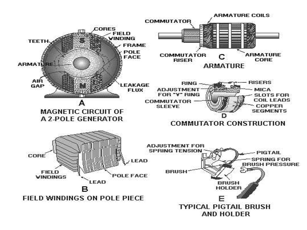
Constructional features of DC Machine
Yoke: The outer frame of a generator or motor is called as yoke. Yoke is made up of cast iron or steel. Yoke provides mechanical strength for whole assembly of the generator (or motor). It also carries the magnetic flux produced by the poles. Poles: Poles are joined to the yoke with the help of screws or welding. Poles are to support field windings. Field winding is wound on poles and connected in series or parallel with armature winding or sometimes separately. Pole shoe: Pole shoe is an extended part of the pole which serves two purposes, (i)to prevent field coils from slipping and (ii)to spread out the flux in air gap uniformly.
. It also carries the magnetic flux produced by the poles. Poles: Poles are joined to the yoke with the help of screws or welding. Poles are to support field windings. Field winding is wound on poles and connected in series or parallel with armature winding or sometimes separately. Pole shoe: Pole shoe is an extended part of the pole which serves two purposes, (i)to prevent field coils from slipping and (ii)to spread out the flux in air gap uniformly.")
19
Armature Core(rotor)
")
20
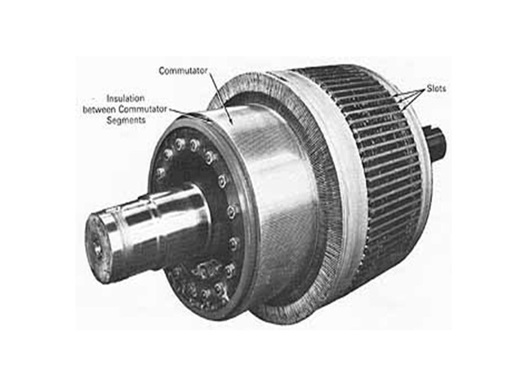
Commutator

21
Armature core (rotor) Armature core: Armature core is the rotor of a generator. Armature core is cylindrical in shape on which slots are provided to carry armature windings. Commutator and brushes: As emf is generated in the armature conductors terminals must be taken out to make use of generated emf. But if we can't directly solder wires to commutator conductors as they rotates. Thus commutator is connected to the armature conductors and mounted on the same shaft as that of armature core. Conducting brushes rest on commutator and they slides over when rotor (hence commutator) rotates. Thus brushes are physically in contact with armature conductors hence wires can be connected to brushes.
 rotates. Thus brushes are physically in contact with armature conductors hence wires can be connected to brushes.")
22
Armature Windings LAP WINDING WAVE WINDING
1. lap winding is high current, low voltage 1.wave winding is low current, high voltage. 2.IN LAP winding,if connection is in started form conductor in slot,then connections overlap each other as winding proceeds till startng point is reached again. 2.IN WAVE type of connection winding always travels ahead avoiding overlapping.it travels like a progressive wave 3.IN LAP winding, no. of parallel paths = holes i.e,A=P=4 3.IN WAVE winding,no. of parallel paths=2 4.LAP winding is preferrable for high current low voltage capacity generator 4.WAVE winding is preferrable for high voltage low current capacity generator 5.Lap windings are also used for applications requiring lower voltages at higher currents 5.Wave windings are used for applications requiring higher voltages at lower currents

23
LAP WINDING & WAVE WINDING

24
Classification of DC generators(methods of excitation)
when the current is passing through the winding then it is called "Excitation". Types of Excitation: (1)seperately excited generator. (2)self excited generator. Self Generator is classified into 3 types. 1.shunt generator. 2.series generator. 3.compound generator. Compoud Generator is again classified into 2 types. 1.short shunt generator. 2.long shunt generator.
seperately excited generator. (2)self excited generator. Self Generator is classified into 3 types. 1.shunt generator. 2.series generator. 3.compound generator. Compoud Generator is again classified into 2 types. 1.short shunt generator. 2.long shunt generator.")
25
Symbolic representation of dc generators

26
Separatly excited DC Generator

27
Characteristics of Separately Excited DC Generator
The characteristics is separately excited d.c. generator are divided into two types, 1) Magnetization and ) Load characteristics. 1.1 Magnetization or Open Circuit Characteristics The arrangement to obtain this characteristics is shown in the Fig. 1.
 Magnetization and 2) Load characteristics. 1.1 Magnetization or Open Circuit Characteristics. The arrangement to obtain this characteristics is shown in the Fig. 1.")
28
The rheostat as a potential driver is used to control the field current and the flux. It is varied from zero and is measured on ammeter connected. Eo = (ΦPNZ)/(60A) As If is varied, then Φ change and hence induced e.m.f. Eo also varies. It is measured on voltmeter connected across armature. No Load is connected to machine, hence characteristics are also called no load characteristics which is graph of Eo against field current If as shown in the Fig. 2. As If increases, flux Φ increases and Eo increases. After point A, saturation occurs when Φ becomes constant and hence Eo saturates.
/(60A) As If is varied, then Φ change and hence induced e.m.f. Eo also varies. It is measured on voltmeter connected across armature. No Load is connected to machine, hence characteristics are also called no load characteristics which is graph of Eo against field current If as shown in the Fig. 2. As If increases, flux Φ increases and Eo increases. After point A, saturation occurs when Φ becomes constant and hence Eo saturates.")
29
1.2 Load Saturation Curve This is the graph of terminal voltage Vt against field current If. When generator is loaded, armature current Ia flows and armature reaction exists. Due to this, terminal voltage Vt is less than the no load rated voltage. On no load, current Ia is zero and armature reaction is absent. Hence less number of ampere turns are required to produce rated voltage Eo . These ampere-turns are equal to OB as shown in the Fig. 3. On load, to produce same voltage more field ampere-turns are required due to demagnetizating effect of armature reaction. These are equal to BC as shown in the Fig. 3. Similarly there is drop Ia Ra across armature resistance. Hence terminal voltage V = E - Ia Ra . This graph OR is also shown in the Fig. 3. The triangle PQR is called drop reaction triangle. Thus OP is no load saturation curve, OQ is the graph of generated voltage on load and OR is the graph of terminal voltage on load.

30
Internal and External Characteristics External
Let be the no load rated voltage which drops to E due to armature reaction on load and further drops to Vt due to armature resistance drop Ia Ra on load. The graph of Vt against load current IL is called external characteristics while the graph of E against load current IL is called internal characteristics. These are shown in the Fig. 4. for separately excited d.c.generator. The graphs are to be plotted for constant field current. In case of separately excited d.c. generator induced e.m.f. is totally dependent on flux Φ i.e. field current If . Hence to have control over the field current, in case of separately excited d.c. generators field regulator is necessary.

31
Difference between Self Excited and Separately Excited DC Generator
Self Excited DC Generator Seperaty Excited DC Generator 1.In self excited dc generators the coil gets the excitation voltage from the voltage generated in it after a time period but not in the starting itself, 1.in separately excited generator an external supply is must for supplying exciting voltage to the coil 2.self excited generator works on its own feedback 2.separately excited generator need a external source to work

32
Self Excited Generator

33
Shunt Generator A shunt generator is a method of generating electricity in which field winding and armature winding are connected in parallel, and in which the armature supplies both the load current and the field current.

34
Voltage and Current Relations
Current in the field windings of a shunt-wound generator is independent of the load current (currents in parallel branches are independent of each other). Since field current, and therefore field strength, is not affected by load current, the output voltage remains more nearly constant than does the output voltage of the series-wound generator. In actual use, the output voltage in a dc shunt-wound generator varies inversely as load current varies. The output voltage decreases as load current increases because the voltage drop across the armature resistance increases (E = IR).
. Since field current, and therefore field strength, is not affected by load current, the output voltage remains more nearly constant than does the output voltage of the series-wound generator. In actual use, the output voltage in a dc shunt-wound generator varies inversely as load current varies. The output voltage decreases as load current increases because the voltage drop across the armature resistance increases (E = IR).")
35
Shunt Generator and its Characteristics
In these types of generators the field windings, armature windings and external load circuit all are connected in series as shown in figure below.

36
Series Wound DC Generator
Therefore, the same electric current flows through armature winding, field winding and the load. Let, I = Ia = Isc = IL Here, Ia = armature current Isc = series field current IL = load current There are generally three most important characteristics of series wound DC generator which show the relation between various quantities such as series field electric current or excitation current, generated voltage, terminal voltage and load current.

37
Compound Generators

38
In compound wound DC generators both the field windings are combined (series and shunt). This type of generators can be used as either long shunt or short shunt compound wound generators as shown in the diagram below. In both the cases the external characteristic of the generator will be nearly same. The compound wound generators may be cumulatively compounded or differentially compounded (discussed earlier in the type of generators). Differentially compound wound generators are very rarely used. So, here we mainly concentrate upon the characteristic of cumulatively compound wound generators.
. Differentially compound wound generators are very rarely used. So, here we mainly concentrate upon the characteristic of cumulatively compound wound generators..")
40
We all know that, in series wound DC generators, the output voltage is directly proportional with load current and in shunt wound DC generators, output voltage is inversely proportional with load current. The electric current in the shunt field winding produces a flux which causes a fall in terminal voltage due to armature reaction and ohmic drop in the circuit. But the electric current in the series field also produces a flux which opposes the shunt field flux and compensate the drop in the terminal voltage and try to operate the machine at constant voltage. The combination of a series generator and a shunt generator gives the characteristic of a cumulative compound wound generator. At no load condition there is no electric current in the series field because the load terminals are open circuited. But the shunt field electric current helps to produce field flux and excite the machine. When the dc generator supplies load, the load current increases and electric current flows through the series field. Therefore, series field also provides some field flux and emf is also increased. The voltage drop in the shunt machine is therefore compensated by the voltage rise in the series machine.

42
Applications of Separately Excited DC Generators
These types of DC generators are generally more expensive than self-excited DC generators because of their requirement of separate excitation source. Because of that their applications are restricted. They are generally used where the use of self-excited generators are unsatisfactory. I. Because of their ability of giving wide range of voltage output, they are generally used for testing purpose in the laboratories. II. Separately excited generators operate in a stable condition with any variation in field excitation. Because of this property they are used as supply source of DC motors, whose speeds are to be controlled for various applications. Example- Ward Leonard Systems of speed control.

43
Applications of Shunt Wound DC Generators
The application of shunt generators are very much restricted for its dropping voltage characteristic. They are used to supply power to the apparatus situated very close to its position. These type of DC generators generally give constant terminal voltage for small distance operation with the help of field regulators from no load to full load. I. They are used for general lighting. II. They are used to charge battery because they can be made to give constant output voltage. III. They are used for giving the excitation to the alternators. IV. They are also used for small power supply.

44
Applications of Series Wound DC Generators
These types of generators are restricted for the use of power supply because of their increasing terminal voltage characteristic with the increase in load current from no load to full load. We can clearly see this characteristic from the characteristic curve of series wound generator. They give constant electric current in the dropping portion of the characteristic curve. For this property they can be used as constant current source and employed for various applications. I. They are used for supplying field excitation electric current in DC locomotives for regenerative breaking. II. This types of generators are used as boosters to compensate the voltage drop in the feeder in various types of distribution systems such as railway service. III. In series arc lightening this type of generators are mainly used.

45
Applications of Compound Wound DC Generators
Among various types of DC generators, the compound wound DC generators are most widely used because of its compensating property. We can get desired terminal voltage by compensating the drop due to armature reaction and ohmic drop in the in the line. Such generators have various applications. I. Cumulative compound wound generators are generally used lighting, power supply purpose and for heavy power services because of their constant voltage property. They are mainly made over compounded. II. Cumulative compound wound generators are also used for driving a motor. III. For small distance operation, such as power supply for hotels, offices, homes and lodges, the flat compounded generators are generally used. IV. The differential compound wound generators, because of their large demagnetization armature reaction, are used for arc welding where huge voltage drop and constant electric current is required. At present time the applications of DC generators become very limited because of technical and economic reasons. Now a days the electric power is mainly generated in the form of alternating electric current with the help of various power electronics devices.

46
DC MOTOR

47
Basics of a Electric Motor
dcmotor 47

48
Basics of a Electric Motor
4848 Basics of a Electric Motor dcmotor 48

49
4949 A Two Pole DC Motor dcmotor 49

50
5050 A Four Pole DC Motor dcmotor 50

51
Operating Principle of a DC Machine
5151 Operating Principle of a DC Machine dcmotor 51

52
Fleming’s Left Hand Rule Or Motor Rule
5252 Fleming’s Left Hand Rule Or Motor Rule FORE FINGER = MAGNETIC FIELD 900 THUMB = MOTION MIDDLE FINGER= CURRENT FORCE = B IAl dcmotor 52

53
Fleming’s Right Hand Rule Or Generator Rule
5353 Fleming’s Right Hand Rule Or Generator Rule FORE FINGER = MAGNETIC FIELD 900 900 900 THUMB = MOTION MIDDLE FINGER = INDUCED VOLTAGE VOLTAGE = B l u dcmotor 53

54
5454 Action of a Commutator dcmotor 54

55
5555 Armature of a DC Motor dcmotor 55

56
Generated Voltage in a DC Machine
5656 Generated Voltage in a DC Machine dcmotor 56

57
Armature Winding in a DC Machine
5757 Armature Winding in a DC Machine dcmotor 57

58
Lap Winding of a DC Machine
5858 Lap Winding of a DC Machine Used in high current low voltage circuits Number of parallel paths equals number of brushes or poles dcmotor 58

59
Wave Winding of a DC Machine
5959 Wave Winding of a DC Machine Used in high voltage low current circuits Number of parallel paths always equals 2 dcmotor 59

60
Magnetic circuit of a 4 pole DC Machine
6060 Magnetic circuit of a 4 pole DC Machine dcmotor 60

61
Magnetic circuit of a 2 pole DC Machine
6161 Magnetic circuit of a 2 pole DC Machine dcmotor 61

62
Summary of a DC Machine Basically consists of
6262 Summary of a DC Machine Basically consists of An electromagnetic or permanent magnetic structure called field which is static An Armature which rotates The Field produces a magnetic medium The Armature produces voltage and torque under the action of the magnetic field dcmotor 62

63
Deriving the induced voltage in a DC Machine
6363 Deriving the induced voltage in a DC Machine dcmotor 63

64
Deriving the electromagnetic torque in a DC Machine
6464 Deriving the electromagnetic torque in a DC Machine dcmotor 64

65
Voltage and Torque developed in a DC Machine
6565 Voltage and Torque developed in a DC Machine Induced EMF, Ea = Kam (volts) Developed Torque, Tdev = KaIa (Newton-meter or Nm) where m is the speed of the armature in rad/sec., is the flux per pole in weber (Wb) Ia is the Armature current Ka is the machine constant dcmotor 65
 Developed Torque, Tdev = KaIa (Newton-meter or Nm) where m is the speed of the armature in rad/sec., is the flux per pole in weber (Wb) Ia is the Armature current. Ka is the machine constant. dcmotor. 65.")
66
Interaction of Prime-mover DC Generator and Load
6666 Interaction of Prime-mover DC Generator and Load Tdev Ia + + Prime-mover (Turbine) m Ea VL DC Generator Load - Tpm - Ea is Generated voltage VL is Load voltage Tpm is the Torque generated by Prime Mover Tdev is the opposing generator torque dcmotor 66
 m. Ea. VL. DC Generator. Load. - Tpm. - Ea is Generated voltage. VL is Load voltage. Tpm is the Torque generated by Prime Mover. Tdev is the opposing generator torque. dcmotor. 66.")
67
Interaction of the DC Motor and Mechanical Load
6767 Interaction of the DC Motor and Mechanical Load Ia Tload + Mechanical Load (Pump, Compressor) + VT DC Motor m Ea - - - Tdev Ea is Back EMF VT is Applied voltage Tdev is the Torque developed by DC Motor Tload is the opposing load torque dcmotor 67
 + VT. DC Motor. m. Ea Tdev. Ea is Back EMF. VT is Applied voltage. Tdev is the Torque developed by DC Motor. Tload is the opposing load torque. dcmotor. 67.")
68
Power Developed in a DC Machine
6868 Power Developed in a DC Machine Neglecting Losses, Input mechanical power to dc generator = Tdev m= KaIam =Ea Ia = Output electric power to load Input electrical power to dc motor = Ea Ia= Ka m Ia = Tdev m = Output mechanical power to load dcmotor 68

69
Equivalence of motor and generator
6969 Equivalence of motor and generator In every generator there is a motor (Tdev opposes Tpm) In every motor there is a generator (Ea opposes VT) dcmotor 69
 In every motor there is a generator (Ea opposes VT) dcmotor. 69.")
70
Magnetization Curve 7070 Flux is a non-linear
function of field current and hence Ea is a non-linear function of field current For a given value of flux Ea is directly proportional to m dcmotor 70

71
Separately Excited DC Machine
7171 Separately Excited DC Machine RA + Armature Vf - Field Coil dcmotor 71

72
Shunt Excited DC Machine
7272 Shunt Excited DC Machine Shunt Field Coil Armature RA dcmotor 72

73
Series Excited DC Machine
7373 Series Excited DC Machine RA Armature Series Field Coil dcmotor 73

74
Compound Excited DC Machine
7474 Compound Excited DC Machine Series Field Coil Shunt Field Coil Armature RA If the shunt and series field aid each other it is called a cumulatively excited machine If the shunt and series field oppose each other it is called a differentially dcmotor 74

75
Armature Reaction(AR)
7575 Armature Reaction(AR) AR is the magnetic field produced by the armature current AR aids the main flux in one half of the pole and opposes the main flux in the other half of the pole However due to saturation of the pole faces the net effect of AR is demagnetizing dcmotor 75
 AR is the magnetic field produced by the. armature current. AR aids the main flux in one half of the. pole and opposes the main flux in the. other half of the pole. However due to saturation of the pole. faces the net effect of AR is demagnetizing. dcmotor. 75.")
76
Effects of Armature Reaction
7676 Effects of Armature Reaction The magnetic axis of the AR is 900 electrical (cross) out-of-phase with the main flux. This causes commutation problems as zero of the flux axis is changed from the interpolar position. dcmotor 76
 out-of-phase with the main flux. This causes commutation problems as zero of the flux axis is changed from the interpolar position. dcmotor. 76.")
77
Minimizing Armature Reaction
7777 Minimizing Armature Reaction Since AR reduces main flux, voltage in generators and torque in motors reduces with it. This is particularly objectionable in steel rolling mills that require sudden torque increase. Compensating windings put on pole faces can effectively negate the effect of AR. These windings are connected in series with armature winding. dcmotor 77

78
Minimizing commutation problems
7878 Minimizing commutation problems Smooth transfer of current during commutation is hampered by a) coil inductance and b) voltage due to AR flux in the interpolar axis. This voltage is called reactance voltage. Can be minimized using interpoles. They produce an opposing field that cancels out the AR in the interpolar region. Thus this winding is also connected in series with the armature winding. Note: The UVic lab motors have interpoles in them. This should be connected in series with the armature winding for experiments. dcmotor 78
 coil inductance and. b) voltage due to AR flux in the interpolar axis. This voltage is called reactance voltage. Can be minimized using interpoles. They. produce an opposing field that cancels out the AR in the interpolar region. Thus this winding is also connected in series with the armature winding. Note: The UVic lab motors have interpoles in them. This should be connected in series with the armature winding for experiments. dcmotor. 78.")
79
Separately Excited DC Generator
7979 Separately Excited DC Generator Ra If Rf + + RL Vt + Vf Ea Armature - Field Coil - - Ia Field equation: Vf=RfIf Armature equation: Vt=Ea-IaRa Vt=IaRL, Ea=Kam dcmotor 79

80
Shunt Generators Shunt Field Coil Armature 8080 If Ia Ia – If + Ea + -
RL Vt Field coil has Rfw : Implicit field resistance Ra - Rfc Field equation: Vt=Rf If Rf=Rfw+Rfc Armature equation: Vt=Ea-Ia Ra Vt=(Ia – If) RL, Ea=Kam dcmotor 80
 RL, Ea=Kam. dcmotor. 80.")
81
Voltage build-up of shunt generators
8181 Voltage build-up of shunt generators dcmotor 81

82
Example on shunt generators’ buildup
8282 Example on shunt generators’ buildup For proper voltage build-up the following are required: Residual magnetism Field MMF should aid residual magnetism Field circuit resistance should be less than critical field circuit resistance dcmotor 82

83
Separately Excited DC Motor
8383 Separately Excited DC Motor Ra If Rf + + + Vf Ea Armature Vt - Field Coil - - Ia Field equation: Vf=RfIf Armature equation: Ea=Vt-IaRa Ea=Kam dcmotor 83

84
Separately Excited DC Motor Torque-speed Characteristics
8484 Separately Excited DC Motor Torque-speed Characteristics RA + + Armature Vf Mechanical Load - - Field Coil m T dcmotor 84

85
Speed Control of Separately Excited DC Motor(2)
8585 Speed Control of Separately Excited DC Motor(2) By Controlling Terminal Voltage Vt and keeping If or constant at rated value .This method of speed control is applicable for speeds below rated or base speed. T1<T2< T3 V1<V2<V3 m T1 T2 T3 V1 V2 V3 VT dcmotor 85
 By Controlling Terminal Voltage Vt and keeping If or constant at rated value .This method of speed control is applicable. for speeds below rated or base speed. T1<T2< T3. V1<V2<V3. m. T1. T2. T3. V1. V2. V3. VT. dcmotor. 85.")
86
Speed Control of Separately Excited DC Motor
8686 Speed Control of Separately Excited DC Motor By Controlling(reducing) Field Current If or and keeping Vt at rated value. This method of speed control is applicable for speeds above rated speed. 1> 2> 3 T1<T2< T3 m 1 T1 2 T2 T3 3 dcmotor 86
 Field Current If or and keeping. Vt at rated value. This method of speed control is applicable. for speeds above rated speed. 1> 2> 3. T1<T2< T3. m. 1. T1. 2. T2. T3. 3. dcmotor. 86.")
87
Regions of operation of a Separately Excited DC Motor
8787 Regions of operation of a Separately Excited DC Motor dcmotor 87

88
Separately excited dc motor –Example 2
8888 Separately excited dc motor –Example 2 A separately excited dc motor with negligible armature resistance operates at rpm under no-load with Vt =240V(rated voltage). The rated speed of the motor is 1750 rpm. i) Determine Vt if the motor has to operate at 1200 rpm under no-load. ii) Determine (flux/pole) if the motor has to operate at 2400 rpm under no-load; given that K = 400/. iii) Determine the rated flux per pole of the machine. Solution on Greenboard dcmotor 88
. The rated speed of the motor is 1750 rpm. i) Determine Vt if the motor has to operate at 1200 rpm under no-load. ii) Determine (flux/pole) if the motor has to operate at 2400 rpm. under no-load; given that K = 400/. iii) Determine the rated flux per pole of the machine. Solution on Greenboard. dcmotor. 88.")
89
Series Excited DC Motor Torque-Speed Characteristics
8989 Series Excited DC Motor Torque-Speed Characteristics Ra Rsr Rae + Armature Series Field Coil - T m dcmotor 89

90
9090 Losses in dc machines dcmotor 90

91
Losses in dc machines-shunt motor example
9191 Losses in dc machines-shunt motor example If Ia Ia – If + + Vt Ea Shunt Field Coil - - Armature Mechanical Load Field coil has Rfw : Implicit field resistance Ra Rfc Armature equation: Vt=Ea+Ia Ra Ea=Kam Field equation: Vt=Rf If Rf=Rfw+Rfc dcmotor

92
Losses in DC machine Copper Losses or Electrical losses.
Iron Losses or Core Losses. Brush Losses. Mechanical Losses. Stray Load Losses.

93
The End

Similar presentations


>")
>")


