Download presentation
Presentation is loading. Please wait.

1
Protection of Power Systems
9. Differential Relays

2
Differential relays are commonly used to protect generators, buses, and transformers.
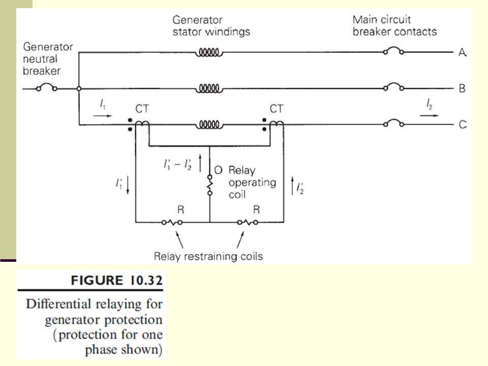
Figure illustrates the basic method of differential relaying for generator protection. The protection of only one phase is shown. The method is repeated for the other two phases. When the relay in any one phase operates, all three phases of the main circuit breaker will open, as well as the generator neutral and field breakers (not shown).
.")
4
For the case of no internal fault within the generator windings, 𝐼 1 = 𝐼 2 , and, assuming identical CTs, 𝐼 1 ′ = 𝐼 2 ′ . For this case the current in the relay operating coil is zero, and the relay does not operate. On the other hand, for an internal fault such as a phase-to-ground or phase-to-phase short within the generator winding, 𝐼 1 ≠ 𝐼 2 , and 𝐼 1 ′ ≠ 𝐼 2 ′ . Therefore, a difference current 𝐼 1 ′ − 𝐼 2 ′ flows in the relay operating coil, which may cause the relay to operate. Since this relay operation depends on a difference current, it is called a differential relay.

5
An electromechanical differential relay called a balance beam relay is shown in Figure 10.33.
The relay contacts close if the downward force on the right side exceeds the downward force on the left side. The electromagnetic force on the right, operating coil is proportional to the square of the operating coil mmf—that is, to [ N 0 𝐼 1 ′ − 𝐼 2 ′ ] 2 . Similarly, the electromagnetic force on the left, restraining coil is proportional to [ N r 𝐼 1 ′ + 𝐼 2 ′ /2] 2 .

7
The condition for relay operation is then
Taking the square root: where

8
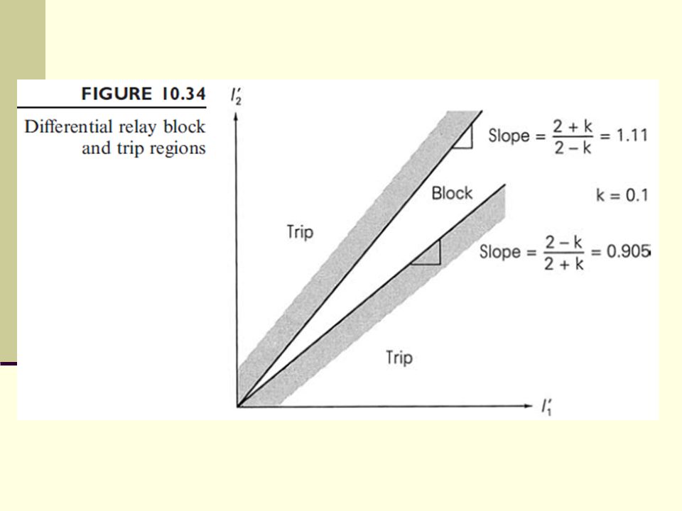
Assuming 𝐼 1 ′ and 𝐼 2 ′ are in phase,
The above equation is plotted in Figure to obtain the block and trip regions of the differential relay for k = 0.1. Note that as k increases, the block region becomes larger; that is, the relay becomes less sensitive.

10
In practice, no two CTs are identical, and the differential relay current 𝐼 1 ′ − 𝐼 2 ′ can become appreciable during external faults, even though 𝐼 1 = 𝐼 2 . The balanced beam relay solves this problem without sacrificing sensitivity during normal currents, since the block region increases as the currents increase, as shown in Figure Also, the relay can be easily modified to enlarge the block region for very small currents near the origin, in order to avoid false trips at low currents.

11
Note that differential relaying provides primary zone protection without backup.
Coordination with protection in adjacent zones is eliminated, which permits high speed tripping. Precise relay settings are unnecessary. Also, the need to calculate system fault currents and voltages is avoided.

12
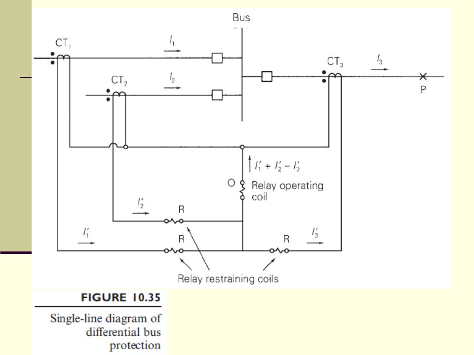
Bus Protection Differential bus protection is illustrated by the single-line diagram of Figure In practice, three differential relays are required, one for each phase. Operation of any one relay would cause all of the three-phase circuit breakers connected to the bus to open, thereby isolating the three-phase bus from service.

14
For the case of no internal fault between the CTs (that is, no bus fault) 𝐼 1 + 𝐼 2 = 𝐼 3 .
Assuming identical CTs, the differential relay current 𝐼 1 ′ + 𝐼 2 ′ − 𝐼 3 ′ equals zero, and the relay does not operate. However, if there is a bus fault, the differential current 𝐼 1 ′ + 𝐼 2 ′ − 𝐼 3 ′ , which is not zero, flows in the operating coil to operate the relay. Use of the restraining coils overcomes the problem of nonidentical CTs.

15
A problem with differential bus protection can result from different levels of fault currents and varying amounts of CT saturation. For example, consider an external fault at point P in Figure Each of the CT1 and CT2 primaries carries part of the fault current, but the CT3 primary carries the sum 𝐼 3 = 𝐼 1 + 𝐼 2 . CT3, energized at a higher level, will have more saturation, such that 𝐼 3 ′ ≠ 𝐼 1 ′ + 𝐼 2 ′ .

16
If the saturation is too high, the differential current in the relay operating coil could result in a false trip. This problem becomes more difficult when there are large numbers of circuits connected to the bus.

17
Transformer Protection
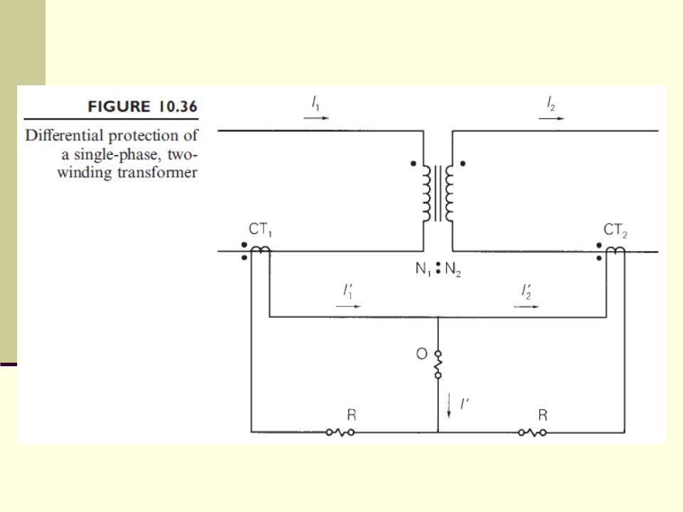
The protection method used for power transformers depends on the transformer MVA rating. Fuses are often used to protect transformers with small MVA ratings, whereas differential relays are commonly used to protect transformers with ratings larger than 10 MVA. The differential protection method is illustrated in Figure for a single-phase, two-winding transformer.

19
Denoting the turns ratio of the primary and secondary CTs by 1/n1 and 1/n2, respectively (a CT with 1 primary turn and n secondary turns has a turns ratio a = 1/n), the CT secondary currents are and the current in the relay operating coil is

20
For the case of no fault between the CTs—that is, no internal transformer fault—the primary and secondary currents for an ideal transformer are related by

21
To prevent the relay from tripping for the case of no internal transformer fault, the differential relay current 𝐼 ′ must be zero. Therefore, we select The value of k can be selected to control the size of the block region shown in Figure 10.34, thereby controlling relay sensitivity.

23
A common problem in differential transformer protection is the mismatch of relay currents that occurs when standard CT ratios are used. If the primary winding in Example 10.9 has a 138-kV instead of 80-kV rating, then I 1rated = 10× × =72.46 A, and a 100:5 primary CT would give I 1 ′ = =3.62 A at rated conditions. This current does not balance I 2 ′ =4.71 A using a 5:600 secondary CT, nor I 2 ′ =3.13 A using a 5:800 secondary CT. The mismatch is about 15%.

24
One solution to this problem is to use auxiliary CTs, which provide a wide range of turns ratios.
A 5:5.76 auxiliary CT connected to the 5:600 secondary CT in the above example would reduce I 2 ′ to =3.62 A, which does balance I 1 ′ . Unfortunately, auxiliary CTs add their own burden to the main CTs and also increase transformation errors.

25
A better solution is to use tap settings on the relays themselves, which have the same effect as auxiliary CTs. Most transformer differential relays have taps that provide for differences in restraining windings in the order of 2 or 3 to 1.

26
When a transformer is initially energized, it can draw a large ‘‘inrush’’ current, a transient current that flows in the shunt magnetizing branch and decays after a few cycles to a small steady-state value. Inrush current appears as a differential current since it flows only in the primary winding. If a large inrush current does occur upon transformer energization, a differential relay will see a large differential current and trip out the transformer unless the protection method is modified to detect inrush current.

27
One method to prevent tripping during transformer inrush is based on the fact that inrush current is nonsinusoidal with a large second-harmonic component. A filter can be used to pass fundamental and block harmonic components of the differential current 𝐼 ′ to the relay operating coil. Another method is based on the fact that inrush current has a large dc component, which can be used to desensitize the relay.

28
Time-delay relays may also be used to temporarily desensitize the differential relay until the inrush current has decayed to a low value.

29
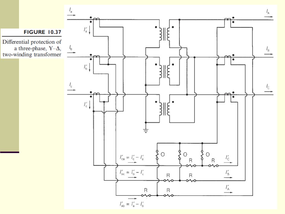
Figure 10.37 illustrates differential protection of a three-phase Y– two-winding transformer.
Note that a Y– transformer produces 30 phase shifts in the line currents. The CTs must be connected to compensate for the 30 phase shifts, such that the CT secondary currents as seen by the relays are in phase. The correct phase-angle relationship is obtained by connecting CTs on the Y side of the transformer in , and CTs on the side in Y.

35
For three-phase transformers (Y–Y, Y–, –Y, –), the general rule is to connect CTs on the Y side in and CTs on the side in Y. This arrangement compensates for the 30 phase shifts in Y– or –Y banks. Note also that zero-sequence current cannot enter a side of a transformer or the CTs on that side, and zero-sequence current on a grounded Y side cannot enter the -connected CTs on that side. Therefore, this arrangement also blocks zero-sequence currents in the differential relays during external ground faults.

36
For internal ground faults, however, the relays can operate from the positive- and negative-sequence currents involved in these faults. Differential protection methods have been modified to handle multiwinding transformers, voltage-regulating transformers, phase-angle regulating transformers, power-rectifier transformers, transformers with special connections (such as zig-zag), and other, special-purpose transformers. Also, other types of relays such as gas-pressure detectors for liquid-filled transformers are used.
, and other, special-purpose transformers. Also, other types of relays such as gas-pressure detectors for liquid-filled transformers are used.")
37
Pilot Relaying Pilot relaying refers to a type of differential protection that compares the quantities at the terminals via a communication channel rather than by a direct wire interconnection of the relays. Differential protection of generators, buses, and transformers considered in previous sections does not require pilot relaying because each of these devices is at one geographical location where CTs and relays can be directly interconnected. However, differential relaying of transmission lines requires pilot relaying because the terminals are widely separated (often by many kilometers).
.")
38
In actual practice, pilot relaying is typically applied to short transmission lines (up to 80 km) with 69 to 115 kV ratings. Four types of communication channels are used for pilot relaying: Pilot wires Power-line carrier (PLC) Microwave Fiber optic cable
 Microwave. Fiber optic cable.")
39
Pilot wires: Separate electrical circuits operating at dc, 50 to 60 Hz, or audio frequencies. These could be owned by the power company or leased from the telephone company. Power-line carrier (PLC): The transmission line itself is used as the communication circuit, with frequencies between 30 and 300 kHz being transmitted. The communication signals are applied to all three phases using an L–C voltage divider and are confined to the line under protection by blocking filters called line traps at each end.
: The transmission line itself is used as the communication circuit, with frequencies between 30 and 300 kHz being transmitted. The communication signals are applied to all three phases using an L–C voltage divider and are confined to the line under protection by blocking filters called line traps at each end.")
40
Microwave: A 2 to 12 GHz signal transmitted by line-of-sight paths between terminals using dish antennas. Fiber optic cable: Signals transmitted by light modulation through electrically nonconducting cable. This cable eliminates problems due to electrical insulation, inductive coupling from other circuits, and atmospheric disturbances.

41
Two common fault detection methods are directional comparison, where the power flows at the line terminals are compared, and phase comparison, where the relative phase angles of the currents at the terminals are compared. Also, the communication channel can either be required for trip operations, which is known as a transfer trip system, or not be required for trip operations, known as a blocking system. A particular pilot-relaying method is usually identified by specifying the fault-detection method and the channel use.

42
The four basic combinations are:
directional comparison blocking, directional comparison transfer trip, phase comparison blocking, and phase comparison transfer trip. Like differential relays, pilot relays provide primary zone protection without backup. Thus, coordination with protection in adjacent zones is eliminated, resulting in high-speed tripping. Precise relay settings are unnecessary. Also, the need to calculate system fault currents and voltages is eliminated.

Similar presentations


>")


